
FLU77-4 or equivalent


NUD105-R025D or equivalent
SECTION 418-00: Module Communications Network
| 2014 Mustang Workshop Manual
|
DIAGNOSIS AND TESTING
| Procedure revision date: 01/11/2013
|
| Fluke 77-IV Digital Multimeter
FLU77-4 or equivalent |
| Vehicle Communication Module (VCM) and Integrated Diagnostic System (IDS) software with appropriate hardware, or equivalent scan tool
|
| Flex Probe Kit
NUD105-R025D or equivalent |
Principles of Operation
Both High Speed Controller Area Network (HS-CAN) and Medium Speed Controller Area Network (MS-CAN) use an unshielded twisted pair cable of data (+) and data (-) circuits. The HS-CAN operates at a maximum data transfer speed of 500 Kbps and designed for real-time information transfer and control. The MS-CAN operates at a maximum data transfer speed of 125 Kbps for bus messages and is designed for general information transfer.
Controller Area Network (CAN) Fault Tolerance
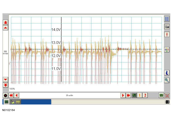
NOTE: The oscilloscope traces below are from the Integrated Diagnostic System (IDS) oscilloscope taken using the IDS pre-configured CAN settings. The traces are for both data (+) and data (-) taken simultaneously (2-channel) at a sample rate of 1 mega-sample per second (1MS/s) or greater.
Traces below are viewed at 500mV per division (vertical axis) and 20 microseconds (20μs) per division (horizontal axis). Readings taken with a different oscilloscope vary from those shown. Compare any suspect readings to a known good vehicle.
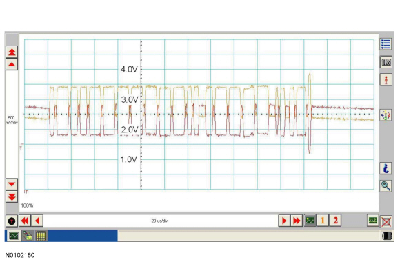
The data (+) and data (-) circuits are each regulated to approximately 2.5 volts during neutral or rested network traffic. As messages are sent on the data (+) circuit, voltage is increased by approximately 1.0 volt. Inversely, the data (-) circuit is reduced by approximately 1.0 volt when a message is sent.
Successful communication of a message can usually be identified by the slight spike at the end of a message transmission. Any signals that are significantly different than the normal CAN waveform may cause network DTCs (U-codes) to set or may cause a complete network outage.
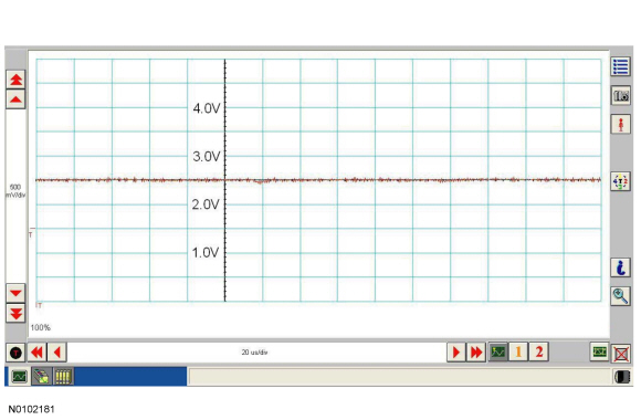
In the event the data (+) and data (-) circuits become shorted together, the signal stays at base voltage (2.5V) continuously and all communication capabilities are lost.
In the event the data (+) circuit becomes shorted to ground, both the data (+) and data (-) circuits are pulled low (0V) and all communication capabilities are lost.
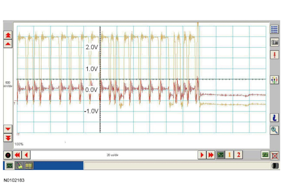
In the event the data (-) circuit becomes shorted to ground, the data (-) circuit is pulled low (0V) and the data (+) circuit reaches near-normal peak voltage (3.0V) during communication but falls to 0V instead of normal base voltage (2.5V). Communication may continue but at a degraded level.
In the event the data (+) circuit becomes shorted to battery voltage, the data (+) circuit is pulled high (12V) and the data (-) circuit falls to abnormally high voltage (above 5V) during communication and reaches battery voltage (12V) for peak voltage. Communication may continue but at a degraded level.

In the event the data (-) circuit becomes shorted to battery voltage, both the data (+) and data (-) circuits are pulled high (12V) and all communication capabilities are lost.
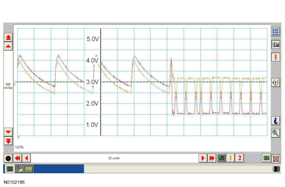
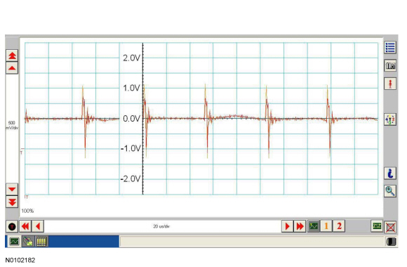
Rhythmic oscillations, inductive spikes or random interference can disrupt the network communications. The corruption signal source may be outside electrical interference such as motors or solenoids or internal interference generated from a module on the network. In some cases, an open in either the data (+) or data (-) circuit to a network module may cause the module to emit interference on the one circuit which is still connected. The trace shown is an example of a "sawtooth" pattern transmitted from a module with one open network circuit.
Other corruptions may be present when a module is intermittently powered up and down. The module on power up may initiate communication out of sync with other modules on the network causing momentary communication outages.
Controller Area Network (CAN) Multiplex Messages
Modules on the CAN utilize simultaneous communication of two or more messages on the same network circuits. The following chart summarizes the messages sent and received on the network.
CAN Module Communication Message Chart
NOTE: This chart describes the specific High Speed Controller Area Network (HS-CAN) and Medium Speed Controller Area Network (MS-CAN) messages broadcast by each module, and the module(s) that receive the message.
| Broadcast Message | Originating Module | Network Type | Receiving Module(s) |
|---|---|---|---|
| A/C clutch engagement request | HVAC module | MS-CAN |
|
| A/C clutch engagement request (gateway) | IPC | HS-CAN |
|
| A/C clutch engagement status | PCM | HS-CAN |
|
| A/C clutch engagement status (gateway) | IPC | MS-CAN |
|
| A/C recirculation mode request | PCM | HS-CAN |
|
| A/C recirculation mode request (gateway) | IPC | MS-CAN |
|
| ABS event in progress | ABS module | HS-CAN |
|
| ABS Roll Stability Control (RSC®) chime malfunction status | ABS module | HS-CAN |
|
| ABS warning indicator request | ABS module | HS-CAN |
|
| Accelerator pedal position | PCM | HS-CAN |
|
| Accelerometer and yaw sensor data | ABS module | HS-CAN |
|
| Accelerometer and yaw sensor data (gateway) | IPC | MS-CAN |
|
| Accessory delay status | SJB | MS-CAN |
|
| Airbag deployment eCall confirmation | APIM | HS-CAN |
|
| Airbag deployment eCall notification | IPC | MS-CAN |
|
| Airbag deployment event data record | PCM | HS-CAN |
|
| Airbag deployment status | RCM | HS-CAN |
|
| Airbag deployment status (gateway) | IPC | MS-CAN |
|
| Airbag warning indicator request | RCM | HS-CAN |
|
| Airbag warning indicator status | IPC | HS-CAN |
|
| Ambient lighting color | IPC | MS-CAN |
|
| Ambient lighting dimming level | IPC | MS-CAN |
|
| Ambient lighting status | BCM-B | MS-CAN |
|
| Ambient temperature, inferred | PCM | HS-CAN |
|
| Autolamp delay command | IPC | MS-CAN |
|
| Autolamp delay status | SJB | MS-CAN |
|
| Autolock command | IPC | MS-CAN |
|
| Autolock status | SJB | MS-CAN |
|
| Auto-unlock command | IPC | MS-CAN |
|
| Auto-unlock status | SJB | MS-CAN |
|
| Average fuel economy data | IPC | MS-CAN |
|
| Average fuel economy reset request (navigation) | ACM | MS-CAN |
|
| Axle ratio | PCM | HS-CAN |
|
| Barometric pressure | PCM | HS-CAN |
|
| Barometric pressure (gateway) | IPC | MS-CAN |
|
| Belt-Minder® programming request | RCM | HS-CAN |
|
| Belt-Minder® warning status | RCM | HS-CAN |
|
| Belt-Minder® warning status (gateway) | IPC | MS-CAN |
|
| Brake (red) warning indicator request | SJB | MS-CAN |
|
| Brake fluid level low | SJB | MS-CAN |
|
| Brake fluid level low (gateway) | IPC | HS-CAN |
|
| Brake lamp on demand | IPC | MS-CAN |
|
| Brake lamp switch status | PCM | HS-CAN |
|
| Charging system status | PCM | HS-CAN |
|
| Charging system warning indicator request | PCM | HS-CAN |
|
| Compass display data | IPC | MS-CAN |
|
| Compass zone and calibration status | IPC | MS-CAN |
|
| Convertible top position status | BCM-B | MS-CAN |
|
| Damper mode status | VDM | HS-CAN |
|
| Decklid ajar status | SJB | MS-CAN |
|
| Door ajar status | SJB | MS-CAN |
|
| Door lock command | SJB | MS-CAN |
|
| Door lock command source | SJB | MS-CAN |
|
| Engine coolant temperature | PCM | HS-CAN |
|
| Engine coolant temperature (gateway) | IPC | MS-CAN |
|
| Engine fail-safe cooling mode status | PCM | HS-CAN |
|
| Engine fail-safe Electronic Throttle Control (ETC) warning indicator request | PCM | HS-CAN |
|
| Engine Malfunction Indicator Lamp (MIL) request | PCM | HS-CAN |
|
| Engine off timer | PCM | HS-CAN |
|
| Engine off timer (gateway) | IPC | MS-CAN |
|
| Engine oil life | PCM | HS-CAN |
|
| Engine RPM | PCM | HS-CAN |
|
| Engine RPM (gateway) | IPC | MS-CAN |
|
| Engine torque data | PCM | HS-CAN |
|
| Engine torque reduction request | ABS module | HS-CAN |
|
| Engine turbocharger boost | PCM | HS-CAN |
|
| Engine type | PCM | HS-CAN |
|
| English/metric display (navigation) | ACM | MS-CAN |
|
| English/metric mode | IPC | MS-CAN |
|
| Front Controls Interface Module (FCIM) button press data | FCIM | MS-CAN |
|
| Fuel cap off indicator request | PCM | HS-CAN |
|
| Fuel economy information | IPC | MS-CAN |
|
| Fuel flow data | PCM | HS-CAN |
|
| Fuel level (instant) | IPC | HS-CAN |
|
| Fuel level status | IPC | MS-CAN |
|
| Fuel level status | IPC | HS-CAN |
|
| Fuel pump cutoff request | RCM | HS-CAN |
|
| Global Positioning System (GPS) data | Global Positioning System Module (GPSM) | MS-CAN |
|
| Headlamp high beam indicator request | SJB | MS-CAN |
|
| Headlamp low beam status | SJB | MS-CAN |
|
| Headlamps on warning chime command | SJB | MS-CAN |
|
| Hood ajar status | SJB | MS-CAN |
|
| HVAC button status | FCIM | MS-CAN |
|
| HVAC button status, navigation Audio Front Control Module (ACM) | ACM | MS-CAN |
|
| HVAC indicator status | HVAC module | MS-CAN |
|
| HVAC module display data | HVAC module | MS-CAN |
|
| HVAC temperature display | HVAC module | MS-CAN |
|
| HVAC voice request | ACM | MS-CAN |
|
| Ignition switch position | SJB | MS-CAN |
|
| Ignition switch position (gateway) | IPC | HS-CAN |
|
| Integrated Keyhead Transmitter (IKT) programming request | IPC | MS-CAN |
|
| IKT programming status | SJB | MS-CAN |
|
| Illuminated entry/exit status | SJB | MS-CAN |
|
| Instrument illumination level | SJB | MS-CAN |
|
| Interior courtesy lamp battery saver status | SJB | MS-CAN |
|
| Interior courtesy lamp delay status | SJB | MS-CAN |
|
| Interior courtesy lamp door status | SJB | MS-CAN |
|
| Interior courtesy lamp illuminated entry status | SJB | MS-CAN |
|
| Key-in-ignition status | SJB | MS-CAN |
|
| Key-in-ignition warning chime command | SJB | MS-CAN |
|
| Low odometer status | IPC | MS-CAN |
|
| Manual transmission clutch top travel switch status | PCM | HS-CAN |
|
| Manual transmission upshift indicator request | PCM | HS-CAN |
|
| MyKey request | IPC | HS-CAN |
|
| Navigation rolling wheel count | ABS module | HS-CAN |
|
| Navigation rolling wheel count (gateway) | IPC | MS-CAN |
|
| Occupant Classification System (OCS) calibration data | OCSM | HS-CAN |
|
| OCS fault status | OCSM | HS-CAN |
|
| OCS sensor data | OCSM | HS-CAN |
|
| OCS serial number | OCSM | HS-CAN |
|
| Odometer rolling count | PCM | HS-CAN |
|
| Park aid request | IPC | HS-CAN |
|
| Park aid status | PAM | HS-CAN |
|
| Park brake chime request | SJB | MS-CAN |
|
| Park brake status | SJB | MS-CAN |
|
| Park brake status (gateway) | IPC | HS-CAN |
|
| Park lamp status | SJB | MS-CAN |
|
| Passenger seat belt buckle status | RCM | HS-CAN |
|
| Passive Anti-Theft System (PATS) security data | IPC | HS-CAN |
|
| PATS security data | PCM | HS-CAN |
|
| PATS security data | IPC | MS-CAN |
|
| Perimeter alarm chime request | SJB | MS-CAN |
|
| Perimeter alarm courtesy lamp status | SJB | MS-CAN |
|
| Perimeter alarm event trigger source | SJB | MS-CAN |
|
| Perimeter alarm inclination armed status | SJB | MS-CAN |
|
| Perimeter alarm inclination sensor status | BCM-B | MS-CAN |
|
| Perimeter alarm inclination/intrusion sensor fault | BCM-B | MS-CAN |
|
| Perimeter alarm intrusion armed status | SJB | MS-CAN |
|
| Perimeter alarm intrusion sensor status | BCM-B | MS-CAN |
|
| PSCM fault status | PSCM | HS-CAN |
|
| Restraints Control Module (RCM) serial number | RCM | HS-CAN |
|
| Remote start status | SJB | MS-CAN |
|
| Seat belt indicator request | RCM | HS-CAN |
|
| Seat belt warning chime request | RCM | HS-CAN |
|
| Seat belt warning chime status | IPC | HS-CAN |
|
| Slow vehicle speed puddle lamp status | SJB | MS-CAN |
|
| Speed control indicator status | PCM | HS-CAN |
|
| Stability control event in progress | ABS module | HS-CAN |
|
| Stability control indicator status | ABS module | HS-CAN |
|
| Stability control message center text | ABS module | HS-CAN |
|
| Steering wheel angle | PSCM | HS-CAN |
|
| Steering wheel angle offset | ABS module | HS-CAN |
|
| Tire revolutions per mile | PCM | HS-CAN |
|
| Tire size information | ABS module | HS-CAN |
|
| Tire size information (gateway) | IPC | MS-CAN |
|
| Tire Pressure Monitoring System (TPMS) indicator command | SJB | MS-CAN |
|
| TPMS sensor status | SJB | MS-CAN |
|
| TPMS system status | SJB | MS-CAN |
|
| TPMS tire pressure data | SJB | MS-CAN |
|
| Traction control disable switch status | ABS module | HS-CAN |
|
| Traction control event in progress | ABS module | HS-CAN |
|
| Transmission malfunction indicator request | PCM | HS-CAN |
|
| Transmission overdrive cancel status | PCM | HS-CAN |
|
| Transmission selector (PRNDL) status | PCM | HS-CAN |
|
| Transmission selector (PRNDL) status (gateway) | IPC | MS-CAN |
|
| Transmission shift in progress | PCM | HS-CAN |
|
| Transmission type | PCM | HS-CAN |
|
| Turn signal command | SJB | MS-CAN |
|
| Turn signal outage, LR | BCM-B | MS-CAN |
|
| Turn signal outage, RR | BCM-B | MS-CAN |
|
| Turn signal sequential command | SJB | MS-CAN |
|
| Vehicle speed | PCM | HS-CAN |
|
| Vehicle speed (gateway) | IPC | MS-CAN |
|
| Vehicle type information | PCM | HS-CAN |
|
| Vehicle type information (gateway) | IPC | MS-CAN |
|
| Vehicle Identification Number (VIN) information | PCM | HS-CAN |
|
| VIN information (gateway) | IPC | MS-CAN |
|
| Wheel speed data | ABS module | HS-CAN |
|
Inspection and Verification
Visual Inspection Chart
| Electrical |
|---|
|
NOTE: Make sure to use the latest scan tool software release.
NOTE: The Vehicle Communication Module (VCM) LED prove-out confirms power and ground from the DLC are provided to the VCM .
If the Integrated Diagnostic System (IDS) does not communicate with the VCM :NOTE: The scan tool first attempts to communicate with the PCM, after establishing communication with the PCM, the scan tool then attempts to communicate with all other modules on the vehicle.
If an IDS session cannot be established with the vehicle, ( IDS may state "No communication can be established with the PCM"):DTC Charts
NOTE: Network DTCs (U-codes) are often a result of intermittent concerns such as faulty wiring or low battery voltage occurrences. Additionally, vehicle service procedures such as module reprogramming will often set network DTCs. Replacing a module to resolve a network DTC is unlikely to resolve the concern. To prevent repeat network DTC concerns, inspect all network wiring, especially connectors. Test the vehicle battery, refer to Section 414-01 .
Communication Network DTC Chart
NOTE: DTC U1900 will set in a module that is reporting a communication fault from another module on the data bus. The module that reports the fault is not the problem module.
| DTC | Description | Action |
|---|---|---|
| U0001:88 | High Speed CAN Communication Bus: Bus Off | The module could not communicate on the network at a point in time. The fault is not currently present (the module had to communicate with the scan tool to report this DTC). CLEAR the DTC. REPEAT the Network Test with the scan tool. VERIFY the integrity of the connectors and wiring Refer to Wiring Diagrams Cell 14 , Module Communications Network for schematic and connector information. |
| U0028:08 | Vehicle Communication Bus A: Bus Signal / Message Failure | The module could not communicate on the network at a point in time. The fault is not currently present (the module had to communicate with the scan tool to report this DTC). CLEAR the DTC. REPEAT the Network Test with the scan tool. VERIFY the integrity of the connectors and wiring Refer to Wiring Diagrams Cell 14 , Module Communications Network for schematic and connector information. |
| U0028:88 | Vehicle Communication Bus A: Bus off | The module could not communicate on the network at a point in time. The fault is not currently present (the module had to communicate with the scan tool to report this DTC). CLEAR the DTC. REPEAT the Network Test with the scan tool. VERIFY the integrity of the connectors and wiring Refer to Wiring Diagrams Cell 14 , Module Communications Network for schematic and connector information. |
| U0073 | Control Module Communication Bus Off | The module could not communicate on the network at a point in time. The fault is not currently present (the module had to communicate with the scan tool to report this DTC). CLEAR the DTC. REPEAT the Network Test with the scan tool. VERIFY the integrity of the connectors and wiring Refer to Wiring Diagrams Cell 14 , Module Communications Network for schematic and connector information. |
| U2472 | Unexpected Ignition State | This DTC is only set when an on-demand self-test is run with the test entry conditions not correct. CLEAR the DTC. REPEAT the self-test with the ignition in the ON position and the vehicle stationary. |
| U2473 | Unexpected Vehicle Speed | This DTC is only set when an on-demand self-test is run with the test entry conditions not correct. CLEAR the DTC. REPEAT the self-test with the ignition in the ON position and the vehicle stationary. |
| - | All network DTCs referenced to 418-00 from another section | GO to Symptom Chart . |
| - | All other DTCs | REFER to Section 419-10 . |
Symptom Chart
| Condition | Possible Sources | Action |
|---|---|---|
|
| |
|
|
|
|
| |
|
| |
|
| |
|
| |
|
| |
|
| |
|
| |
|
| |
|
| |
|
| |
|
| |
|
| |
|
| |
|
| |
|
| |
|
| |
|
| |
|
|
Pinpoint Tests
Pinpoint Test A: The PCM Does Not Respond To The Scan Tool
Refer to Wiring Diagrams Cell 14 , Module Communications Network for schematic and connector information.
Refer to Wiring Diagrams Cell 24 , Electronic Engine Controls - 5.0L for schematic and connector information.
Refer to Wiring Diagrams Cell 25 , Electronic Engine Controls - 5.8L for schematic and connector information.
Refer to Wiring Diagrams Cell 26 , Electronic Engine Controls - 3.7L for schematic and connector information.
The PCM communicates with the scan tool through the High Speed Controller Area Network (HS-CAN).
This pinpoint test is intended to diagnose the following:
NOTICE: Use the correct probe adapter(s) when making measurements. Failure to use the correct probe adapter(s) may damage the connector.
NOTE: Failure to disconnect the battery when instructed results in false resistance readings. Refer to Section 414-01 .
| Test Step | Result / Action to Take |
|---|---|
| A1 VERIFY WHETHER OTHER HS-CAN MODULES PASS THE NETWORK TEST | |
| Yes
If "pass" or a DTC was listed next to the PCM, a network fault is not currently present. GO to Pinpoint Test r to diagnose an intermittent HS-CAN fault condition. If "pass" or a DTC was listed next to one or more modules other than the PCM, GO to A2 . No No modules are currently communicating on the HS-CAN . GO to Pinpoint Test r to diagnose no HS-CAN communication. |
| A2 PC/ED MANUAL PINPOINT TEST QA VERIFICATION CHECK | |
| Yes
GO to A3 . No REFER to the Powertrain Control/Emissions Diagnosis (PC/ED) manual, Section 5, pinpoint test QA to diagnose no communication with the PCM. |
| A3 CHECK THE HS-CAN TERMINATION RESISTANCE | |
 | Yes
CONNECT the negative battery cable. GO to A5 . No GO to A4 . |
| A4 CHECK THE CAN CIRCUITS BETWEEN THE PCM AND THE DLC FOR AN OPEN | |
  | Yes
CONNECT the negative battery cable. GO to A5 . No REPAIR the circuit in question. CONNECT the negative battery cable. CLEAR the DTCs. REPEAT the network test with the scan tool. |
| A5 CHECK FOR CORRECT PCM OPERATION | |
| Yes
INSTALL a new PCM. REFER to Section 303-14 . CLEAR the DTCs. REPEAT the network test with the scan tool. No The system is operating correctly at this time. The concern may have been caused by a loose or corroded connector. CLEAR the DTCs. REPEAT the network test with the scan tool. |
Pinpoint Test B: The ABS Module Does Not Respond To The Scan Tool
Refer to Wiring Diagrams Cell 14 , Module Communications Network for schematic and connector information.
Refer to Wiring Diagrams Cell 42 , Vehicle Dynamic Systems for schematic and connector information.
The ABS module communicates with the scan tool through the High Speed Controller Area Network (HS-CAN).
This pinpoint test is intended to diagnose the following:
NOTICE: Use the correct probe adapter(s) when making measurements. Failure to use the correct probe adapter(s) may damage the connector.
NOTE: Failure to disconnect the battery when instructed results in false resistance readings. Refer to Section 414-01 .
| Test Step | Result / Action to Take |
|---|---|
| B1 CHECK THE ABS MODULE VOLTAGE SUPPLY CIRCUITS FOR AN OPEN | |
 | Yes
GO to B2 . No VERIFY the SJB fuse 34 (5A) is OK. If OK, REPAIR the circuit. If not OK, REFER to the Wiring Diagrams manual to identify the possible causes of the circuit short. CLEAR the DTCs. REPEAT the network test with the scan tool. |
| B2 CHECK THE ABS MODULE GROUND CIRCUITS FOR AN OPEN | |
 | Yes
GO to B3 . No REPAIR the circuit in question. CONNECT the negative battery cable. CLEAR the DTCs. REPEAT the network test with the scan tool. |
| B3 CHECK THE HS-CAN CIRCUITS BETWEEN THE ABS MODULE AND THE DLC FOR AN OPEN | |
  | Yes
CONNECT the negative battery cable. GO to B4 . No REPAIR the circuit in question. CONNECT the negative battery cable. CLEAR the DTCs. REPEAT the network test with the scan tool. |
| B4 CHECK FOR CORRECT ABS MODULE OPERATION | |
| Yes
INSTALL a new ABS module. REFER to Section 206-09 . CLEAR the DTCs. REPEAT the network test with the scan tool. No The system is operating correctly at this time. The concern may have been caused by a loose or corroded connector. CLEAR the DTCs. REPEAT the network test with the scan tool. |
Pinpoint Test C: The Instrument Panel Cluster (IPC) Does Not Respond To The Scan Tool
Refer to Wiring Diagrams Cell 14 , Module Communications Network for schematic and connector information.
Refer to Wiring Diagrams Cell 60 , Instrument Cluster for schematic and connector information.
The Instrument Panel Cluster (IPC) communicates with the scan tool through the High Speed Controller Area Network (HS-CAN) and the Medium Speed Controller Area Network (MS-CAN).
This pinpoint test is intended to diagnose the following:
NOTICE: Use the correct probe adapter(s) when making measurements. Failure to use the correct probe adapter(s) may damage the connector.
NOTE: Failure to disconnect the battery when instructed results in false resistance readings. Refer to Section 414-01 .
| Test Step | Result / Action to Take |
|---|---|
| C1 CHECK THE HS-CAN TERMINATION RESISTANCE | |
| Yes
GO to C3 . No GO to C2 . |
| C2 CHECK THE HS-CAN CIRCUITS BETWEEN THE IPC AND THE DLC FOR AN OPEN | |
  | Yes
CONNECT the negative battery cable. GO to C7 . No REPAIR the circuit in question. CONNECT the negative battery cable. CLEAR the DTCs. REPEAT the network test with the scan tool. |
| C3 CHECK THE MS-CAN TERMINATION RESISTANCE | |
 | Yes
GO to C5 . No GO to C4 . |
| C4 CHECK THE MS-CAN CIRCUITS BETWEEN THE IPC AND THE DLC FOR AN OPEN | |
  | Yes
CONNECT the negative battery cable. GO to C7 . No REPAIR the circuit in question. CONNECT the negative battery cable. CLEAR the DTCs. REPEAT the network test with the scan tool. |
| C5 CHECK THE IPC GROUND CIRCUIT FOR AN OPEN | |
 | Yes
CONNECT the negative battery cable. GO to C6 . No REPAIR the circuit. CONNECT the negative battery cable. CLEAR the DTCs. REPEAT the network test with the scan tool. |
| C6 CHECK THE IPC VOLTAGE SUPPLY CIRCUITS FOR AN OPEN | |
 | Yes
TURN the key to the OFF position. GO to C7 . No VERIFY the SJB fuse 26 (10A) or fuse 36 (5A) is OK. If OK, REPAIR the circuit in question. If not OK, REFER to the Wiring Diagrams manual to identify the possible causes of the short circuit. CLEAR the DTCs. REPEAT the network test with the scan tool. |
| C7 CHECK FOR CORRECT IPC OPERATION | |
| Yes
INSTALL a new IPC . REFER to Section 413-01 . CLEAR the DTCs. REPEAT the network test with the scan tool. No The system is operating correctly at this time. The concern may have been caused by a loose or corroded connector. CLEAR the DTCs. REPEAT the network test with the scan tool. |
Pinpoint Test D: The Restraints Control Module (RCM) Does Not Respond To The Scan Tool
Refer to Wiring Diagrams Cell 14 , Module Communications Network for schematic and connector information.
Refer to Wiring Diagrams Cell 46 , Supplemental Restraint System for schematic and connector information.
The Restraints Control Module (RCM) communicates with the scan tool through the High Speed Controller Area Network (HS-CAN).
This pinpoint test is intended to diagnose the following:
 WARNING: Never disassemble or tamper with seat belt deployable components, including pretensioners, load limiters and inflators. Never back probe deployable device electrical connectors. Tampering or back probing may cause an accidental deployment and result in personal injury or death.
WARNING: Never probe the electrical connectors on airbag, Safety Canopy or side air curtain assemblies. Failure to follow this instruction may result in the accidental deployment of these assemblies, which increases the risk of serious personal injury or death.
NOTE: The Supplemental Restraint System (SRS) must be fully operational and free of faults before releasing the vehicle to the customer.
NOTE: Most faults are due to connector and/or wiring concerns. Carry out a thorough inspection and verification before proceeding with the pinpoint test.
NOTE: Failure to disconnect the battery when instructed results in false resistance readings. Refer to Section 414-01 .
| Test Step | Result / Action to Take |
|---|---|
| D1 CHECK THE RCM CONNECTION | |
| Yes
GO to D2 . No REPAIR the RCM connector pins as necessary. REPOWER the SRS . REFER to Section 501-20B . CLEAR the DTCs. REPEAT the network test with the scan tool. |
| D2 CHECK THE RCM VOLTAGE SUPPLY CIRCUIT FOR AN OPEN | |
 | Yes
GO to D3 . No VERIFY the Smart Junction Box (SJB) fuse 31 (10A) is OK. If OK, REPAIR the circuit. If not OK, REFER to the Wiring Diagrams manual to identify the possible causes of the circuit short. CLEAR the DTCs. REPEAT the network test with the scan tool. |
| D3 CHECK THE RCM CASE GROUND | |
| Yes
GO to D4 . No REPAIR the RCM case ground as necessary. CONNECT the negative battery cable. CLEAR the DTCs. REPEAT the network test with the scan tool. |
| D4 CHECK THE HS-CAN CIRCUITS BETWEEN THE RCM AND THE DLC FOR AN OPEN | |
  | Yes
CONNECT the negative battery cable. GO to D5 . No REPAIR the circuit in question. CONNECT the negative battery cable. CLEAR the DTCs. REPEAT the network test with the scan tool. |
| D5 CHECK FOR CORRECT RCM OPERATION | |
| Yes
INSTALL a new RCM . REFER to Section 501-20B . CLEAR the DTCs. REPEAT the network test with the scan tool. No The system is operating correctly at this time. The concern may have been caused by a loose or corroded connector. CLEAR the DTCs. REPEAT the network test with the scan tool. |
Pinpoint Test E: The Occupant Classification System Module (OCSM) Does Not Respond To The Scan Tool
Refer to Wiring Diagrams Cell 14 , Module Communications Network for schematic and connector information.
Refer to Wiring Diagrams Cell 46 , Supplemental Restraint System for schematic and connector information.
The Occupant Classification System Module (OCSM) communicates with the scan tool through the High Speed Controller Area Network (HS-CAN).
This pinpoint test is intended to diagnose the following:
WARNING: Never disassemble or tamper with seat belt deployable components, including pretensioners, load limiters and inflators. Never back probe deployable device electrical connectors. Tampering or back probing may cause an accidental deployment and result in personal injury or death.
NOTICE: Use the correct probe adapter(s) when making measurements. Failure to use the correct probe adapter(s) may damage the connector.
NOTE: The Supplemental Restraint System (SRS) must be fully operational and free of faults before releasing the vehicle to the customer.
NOTE: Most faults are due to connector and/or wiring concerns. Carry out a thorough inspection and verification before proceeding with the pinpoint test.
NOTE: Failure to disconnect the battery when instructed results in false resistance readings. Refer to Section 414-01 .
| Test Step | Result / Action to Take |
|---|---|
| E1 CHECK THE OCSM VOLTAGE SUPPLY CIRCUIT FOR AN OPEN | |
 | Yes
GO to E2 . No VERIFY the Smart Junction Box (SJB) fuse 46 (7.5A) is OK. If OK, REPAIR the circuit. If not OK, REFER to the Wiring Diagrams manual to identify the possible causes of the circuit short. REACTIVATE the SRS . REFER to Section 501-20B . CLEAR the DTCs. REPEAT the network test with the scan tool. |
| E2 CHECK THE OCSM GROUND CIRCUIT FOR AN OPEN | |
 | Yes
GO to E3 . No REPAIR the circuit. REACTIVATE the SRS . CONNECT the negative battery cable. REFER to Section 501-20B . CLEAR the DTCs. REPEAT the network test with the scan tool. |
| E3 CHECK THE HS-CAN CIRCUITS BETWEEN THE OCSM AND THE DLC FOR AN OPEN | |
  | Yes
CONNECT the negative battery cable. GO to E4 . No REPAIR the circuit. REACTIVATE the SRS . CONNECT the negative battery cable. REFER to Section 501-20B . CLEAR the DTCs. REPEAT the network test with the scan tool. |
| E4 CHECK FOR CORRECT OCSM OPERATION | |
| Yes
INSTALL a new OCSM . REFER to Section 501-20B . REACTIVATE the SRS . CLEAR the DTCs. REPEAT the network test with the scan tool. No The system is operating correctly at this time. The concern may have been caused by a loose or corroded connector. REACTIVATE the SRS . REFER to Section 501-20B . CLEAR the DTCs. REPEAT the network test with the scan tool. |
Pinpoint Test F: The Smart Junction Box (SJB) Does Not Respond To The Scan Tool
Refer to Wiring Diagrams Cell 13 , Power Distribution/SJB for schematic and connector information.
Refer to Wiring Diagrams Cell 14 , Module Communications Network for schematic and connector information.
The Smart Junction Box (SJB) communicates with the scan tool through the Medium Speed Controller Area Network (MS-CAN).
This pinpoint test is intended to diagnose the following:
NOTICE: Use the correct probe adapter(s) when making measurements. Failure to use the correct probe adapter(s) may damage the connector.
NOTE: Failure to disconnect the battery when instructed results in false resistance readings. Refer to Section 414-01 .
| Test Step | Result / Action to Take |
|---|---|
| F1 CHECK THE SJB VOLTAGE SUPPLY CIRCUIT FOR AN OPEN | |
 | Yes
GO to F2 . No VERIFY the SJB fuse 5 (10A) is OK. If OK, REPAIR the circuit. CLEAR the DTCs. REPEAT the network test with the scan tool. If not OK, REFER to the Wiring Diagrams manual to identify the possible causes of the circuit short. |
| F2 CHECK THE SJB GROUND CIRCUIT FOR AN OPEN | |
 | Yes
GO to F3 . No REPAIR the circuit. CONNECT the negative battery cable. CLEAR the DTCs. REPEAT the network test with the scan tool. |
| F3 CHECK THE MS-CAN CIRCUITS BETWEEN THE SJB AND THE DLC FOR AN OPEN | |
  | Yes
CONNECT the negative battery cable. GO to F4 . No REPAIR the circuit in question. CONNECT the negative battery cable. CLEAR the DTCs. REPEAT the network test with the scan tool. |
| F4 CHECK FOR CORRECT SJB OPERATION | |
| Yes
INSTALL a new SJB . REFER to Section 419-10 . CLEAR the DTCs. REPEAT the network test with the scan tool. No The system is operating correctly at this time. The concern may have been caused by a loose or corroded connector. CLEAR the DTCs. REPEAT the network test with the scan tool. |
Pinpoint Test G: The Body Control Module B (BCM-B) Does Not Respond To The Scan Tool
Refer to Wiring Diagrams Cell 89 , Interior Lamps for schematic and connector information.
Refer to Wiring Diagrams Cell 14 , Module Communications Network for schematic and connector information.
The Body Control Module B (BCM-B) communicates with the scan tool through the Medium Speed Controller Area Network (MS-CAN).
This pinpoint test is intended to diagnose the following:
NOTICE: Use the correct probe adapter(s) when making measurements. Failure to use the correct probe adapter(s) may damage the connector.
NOTE: Failure to disconnect the battery when instructed results in false resistance readings. Refer to Section 414-01 .
| Test Step | Result / Action to Take |
|---|---|
| G1 CHECK THE BCM-B VOLTAGE SUPPLY CIRCUITS FOR AN OPEN | |
 | Yes
GO to G2 . No VERIFY the Battery Junction Box (BJB) fuse 18 (20A) or Smart Junction Box (SJB) fuse 35 (10A) is OK. If OK, REPAIR the circuit in question. If not OK, REFER to the Wiring Diagrams manual to identify the possible causes of the circuit short. CLEAR the DTCs. REPEAT the network test with the scan tool. |
| G2 CHECK THE BCM-B GROUND CIRCUIT FOR AN OPEN | |
 | Yes
GO to G3 . No REPAIR the circuit. CONNECT the negative battery cable. CLEAR the DTCs. REPEAT the network test with the scan tool. |
| G3 CHECK THE MS-CAN CIRCUITS BETWEEN THE BCM-B AND THE DLC FOR AN OPEN | |
  | Yes
CONNECT the negative battery cable. GO to G4 . No REPAIR the circuit in question. CONNECT the negative battery cable. CLEAR the DTCs. REPEAT the network test with the scan tool. |
| G4 CHECK FOR CORRECT BCM-B OPERATION | |
| Yes
INSTALL a new BCM-B . REFER to Section 419-10 . TEST the system for normal operation. No The system is operating correctly at this time. The concern may have been caused by a loose or corroded connector. CLEAR the DTCs. REPEAT the network test with the scan tool. |
Pinpoint Test H: The HVAC Module Does Not Respond To The Scan Tool
Refer to Wiring Diagrams Cell 14 , Module Communications Network for schematic and connector information.
Refer to Wiring Diagrams Cell 54 , Manual Climate Control for schematic and connector information.
Refer to Wiring Diagrams Cell 55 , Automatic Climate Control System for schematic and connector information.
The HVAC module communicates with the scan tool through the Medium Speed Controller Area Network (MS-CAN).
This pinpoint test is intended to diagnose the following:
NOTICE: Use the correct probe adapter(s) when making measurements. Failure to use the correct probe adapter(s) may damage the connector.
NOTE: Failure to disconnect the battery when instructed results in false resistance readings. Refer to Section 414-01 .
| Test Step | Result / Action to Take |
|---|---|
| H1 CHECK THE HVAC VOLTAGE SUPPLY CIRCUITS FOR AN OPEN | |
 | Yes
GO to H2 . No VERIFY the Smart Junction Box (SJB) fuse 15 (10A) is OK. If OK, REPAIR the circuit in question. CLEAR the DTCs. REPEAT the network test with the scan tool. If not OK, REFER to the Wiring Diagrams manual to identify the possible causes of the circuit short. |
| H2 CHECK THE HVAC GROUND CIRCUIT FOR AN OPEN | |
 | Yes
GO to H3 . No REPAIR the circuit. CONNECT the negative battery cable. CLEAR the DTCs. REPEAT the network test with the scan tool. |
| H3 CHECK THE MS-CAN CIRCUITS BETWEEN THE HVAC MODULE AND THE DLC FOR AN OPEN | |
  | Yes
CONNECT the negative battery cable. GO to H4 . No REPAIR the circuit as necessary. CONNECT the negative battery cable. CLEAR the DTCs. REPEAT the network test with the scan tool. |
| H4 CHECK FOR CORRECT HVAC MODULE OPERATION | |
| Yes
INSTALL a new HVAC module. REFER to Section 412-01 . CLEAR the DTCs. REPEAT the network test with the scan tool. No The system is operating correctly at this time. The concern may have been caused by a loose or corroded connector. CLEAR the DTCs. REPEAT the network test with the scan tool. |
Pinpoint Test I: The Audio Front Control Module (ACM) Does Not Respond To The Scan Tool
Refer to Wiring Diagrams Cell 14 , Module Communications Network for schematic and connector information.
Refer to Wiring Diagrams Cell 130 , Audio System/Navigation for schematic and connector information.
The Audio Front Control Module (ACM) communicates with the scan tool through the Medium Speed Controller Area Network (MS-CAN).
This pinpoint test is intended to diagnose the following:
NOTICE: Use the correct probe adapter(s) when making measurements. Failure to use the correct probe adapter(s) may damage the connector.
NOTE: Failure to disconnect the battery when instructed results in false resistance readings. Refer to Section 414-01 .
| Test Step | Result / Action to Take |
|---|---|
| I1 CHECK THE ACM VOLTAGE SUPPLY CIRCUITS FOR AN OPEN | |
 | Yes
GO to I2 . No VERIFY the SJB fuse 39 (20A) is OK. If OK, REPAIR the circuit in question. If not OK, REFER to the Wiring Diagrams manual to identify the possible causes of the circuit short. CLEAR the DTCs. REPEAT the network test with the scan tool. |
| I2 CHECK THE ACM GROUND CIRCUIT FOR AN OPEN | |
 | Yes
GO to I3 . No REPAIR the circuit. CONNECT the negative battery cable. CLEAR the DTCs. REPEAT the network test with the scan tool. |
| I3 CHECK THE MS-CAN CIRCUITS BETWEEN THE ACM AND THE DLC FOR AN OPEN | |
  | Yes
CONNECT the negative battery cable. GO to I4 . No REPAIR the circuit in question. CONNECT the negative battery cable. CLEAR the DTCs. REPEAT the network test with the scan tool. |
| I4 CHECK FOR CORRECT ACM OPERATION | |
| Yes
INSTALL a new ACM . REFER to Section 415-00 . TEST the system for normal operation. No The system is operating correctly at this time. The concern may have been caused by a loose or corroded connector. CLEAR the DTCs. REPEAT the network test with the scan tool. |
Pinpoint Test J: The Front Controls Interface Module (FCIM) Does Not Respond To The Scan Tool
Refer to Wiring Diagrams Cell 14 , Module Communications Network for schematic and connector information.
Refer to Wiring Diagrams Cell 130 , Audio System/Navigation for schematic and connector information.
The Front Controls Interface Module (FCIM) communicates with the scan tool through the Medium Speed Controller Area Network (MS-CAN).
This pinpoint test is intended to diagnose the following:
NOTICE: Use the correct probe adapter(s) when making measurements. Failure to use the correct probe adapter(s) may damage the connector.
NOTE: Failure to disconnect the battery when instructed results in false resistance readings. Refer to Section 414-01 .
| Test Step | Result / Action to Take |
|---|---|
| J1 CHECK THE FCIM VOLTAGE SUPPLY CIRCUIT FOR AN OPEN | |
 | Yes
GO to J2 . No VERIFY the Smart Junction Box (SJB) fuse 14 (10A) is OK. If OK, REPAIR the circuit in question. If not OK, REFER to the Wiring Diagrams manual to identify the possible causes of the circuit short. CLEAR the DTCs. REPEAT the network test with the scan tool. |
| J2 CHECK THE FCIM GROUND CIRCUIT FOR AN OPEN | |
 | Yes
GO to J3 . No REPAIR the circuit. CONNECT the negative battery cable. CLEAR the DTCs. REPEAT the network test with the scan tool. |
| J3 CHECK THE MS-CAN CIRCUITS BETWEEN THE FCIM AND THE DLC FOR AN OPEN | |
  | Yes
CONNECT the negative battery cable. GO to J4 . No REPAIR the circuit in question. CONNECT the negative battery cable. CLEAR the DTCs. REPEAT the network test with the scan tool. |
| J4 CHECK FOR CORRECT FCIM OPERATION | |
| Yes
INSTALL a new FCIM . REFER to Section 415-00 . CLEAR the DTCs. REPEAT the network test with the scan tool. No The system is operating correctly at this time. The concern may have been caused by a loose or corroded connector. CLEAR the DTCs. REPEAT the network test with the scan tool. |
Pinpoint Test K: The Front Display Interface Module (FDIM) Does Not Respond To The Scan Tool (Without Navigation)
Refer to Wiring Diagrams Cell 14 , Module Communications Network for schematic and connector information.
Refer to Wiring Diagrams Cell 130 , Audio System/Navigation for schematic and connector information.
The Front Display Interface Module (FDIM) (without navigation) communicates with the scan tool through the Medium Speed Controller Area Network (MS-CAN).
This pinpoint test is intended to diagnose the following:
NOTICE: Use the correct probe adapter(s) when making measurements. Failure to use the correct probe adapter(s) may damage the connector.
NOTE: Failure to disconnect the battery when instructed results in false resistance readings. Refer to Section 414-01 .
| Test Step | Result / Action to Take |
|---|---|
| K1 CHECK THE FDIM VOLTAGE SUPPLY CIRCUIT FOR AN OPEN | |
 | Yes
GO to K2 . No VERIFY the Smart Junction Box (SJB) fuse 14 (10A) is OK. If OK, REPAIR the circuit. If not OK, REFER to the Wiring Diagrams manual to identify the possible causes of the circuit short. CLEAR the DTCs. REPEAT the network test with the scan tool. |
| K2 CHECK THE FDIM GROUND CIRCUIT FOR AN OPEN | |
 | Yes
GO to K3 . No REPAIR the circuit. CONNECT the negative battery cable. CLEAR the DTCs. REPEAT the network test with the scan tool. |
| K3 CHECK THE MS-CAN CIRCUITS BETWEEN THE FDIM AND THE DLC FOR AN OPEN | |
  | Yes
CONNECT the negative battery cable. GO to K4 . No REPAIR the circuit in question. CONNECT the negative battery cable. CLEAR the DTCs. REPEAT the network test with the scan tool. |
| K4 CHECK FOR CORRECT FDIM OPERATION | |
| Yes
INSTALL a new FDIM . REFER to Section 415-00 . CLEAR the DTCs. REPEAT the network test with the scan tool. No The system is operating correctly at this time. The concern may have been caused by a loose or corroded connector. CLEAR the DTCs. REPEAT the network test with the scan tool. |
Pinpoint Test L: The Global Positioning System Module (GPSM) Does Not Respond To The Scan Tool
Refer to Wiring Diagrams Cell 14 , Lodule Communications Network for schematic and connector information.
Refer to Wiring Diagrams Cell 130 , Audio System/Navigation for schematic and connector information.
TheGlobal Positioning System Module (GPSM) communicates with the scan tool through the Medium Speed Controller Area Network (MS-CAN).
This pinpoint test is intended to diagnose the following:
NOTICE: Use the correct probe adapter(s) when making measurements. Failure to use the correct probe adapter(s) may damage the connector.
NOTE: Failure to disconnect the battery when instructed results in false resistance readings. Refer to Section 414-01 .
| Test Step | Result / Action to Take |
|---|---|
| L1 CHECK THE GPSM VOLTAGE SUPPLY CIRCUIT FOR AN OPEN | |
 | Yes
GO to L2 . No VERIFY the Smart Junction Box (SJB) fuse 14 (10A) is OK. If OK, REPAIR the circuit in question. If not OK, REFER to the Wiring Diagrams manual to identify the possible causes of the circuit short. CLEAR the DTCs. REPEAT the network test with the scan tool. |
| L2 CHECK THE GPSM GROUND CIRCUIT FOR AN OPEN | |
 | Yes
GO to L3 . No REPAIR the circuit. CONNECT the negative battery cable. CLEAR the DTCs. REPEAT the network test with the scan tool. |
| L3 CHECK THE MS-CAN CIRCUITS BETWEEN THE GPSM AND THE DLC FOR AN OPEN | |
  | Yes
CONNECT the negative battery cable. GO to L4 . No REPAIR the circuit in question. CONNECT the negative battery cable. CLEAR the DTCs. REPEAT the network test with the scan tool. |
| L4 CHECK FOR CORRECT GPSM OPERATION | |
| Yes
INSTALL a new GPSM . REFER to Section 415-00 . CLEAR the DTCs. REPEAT the network test with the scan tool. No The system is operating correctly at this time. The concern may have been caused by a loose or corroded connector. CLEAR the DTCs. REPEAT the network test with the scan tool. |
Pinpoint Test M: The Accessory Protocol Interface Module (APIM) Does Not Respond To The Scan Tool
Refer to Wiring Diagrams Cell 14 , Module Communications Network for schematic and connector information.
Refer to Wiring Diagrams Cell 130 , Audio System/Navigation for schematic and connector information.
The Accessory Protocol Interface Module (APIM) communicates with the scan tool and other modules through the Medium Speed Controller Area Network (MS-CAN) and also communicates with other modules on the High Speed Controller Area Network (HS-CAN).
This pinpoint test is intended to diagnose the following:
NOTICE: Use the correct probe adapter(s) when making measurements. Failure to use the correct probe adapter(s) may damage the connector.
NOTE: Failure to disconnect the battery when instructed results in false resistance readings. Refer to Section 414-01 .
| Test Step | Result / Action to Take |
|---|---|
| M1 CHECK THE APIM VOLTAGE SUPPLY CIRCUIT FOR AN OPEN | |
 | Yes
GO to M2 . No VERIFY the Smart Junction Box (SJB) fuse 3 (15A) is OK. If OK, REPAIR the circuit. CLEAR the DTCs. REPEAT the network test with the scan tool. If not OK, REFER to the Wiring Diagrams manual to identify the possible causes of the circuit short. |
| M2 CHECK THE APIM GROUND CIRCUIT FOR AN OPEN | |
 | Yes
GO to M3 . No REPAIR the circuit in question. CONNECT the negative battery cable. CLEAR the DTCs. REPEAT the network test with the scan tool. |
| M3 CHECK THE HS-CAN CIRCUITS BETWEEN THE APIM AND THE DLC FOR AN OPEN | |
  | Yes
GO to M4 . No REPAIR the circuit in question. CONNECT the negative battery cable. CLEAR the DTCs. REPEAT the network test with the scan tool. |
| M4 CHECK THE MS-CAN CIRCUITS BETWEEN THE APIM AND THE DLC FOR AN OPEN | |
  | Yes
CONNECT the negative battery cable. GO to M5 . No REPAIR the circuit in question. CONNECT the negative battery cable. CLEAR the DTCs. REPEAT the network test with the scan tool. |
| M5 CHECK FOR CORRECT APIM OPERATION | |
| Yes
For diagnosing and testing please refer to the on-line Workshop Manual. If you do not have an on-line subscription, go to www.motorcraftservice.com. No The system is operating correctly at this time. The concern may have been caused by a loose or corroded connector. CLEAR the DTCs. REPEAT the network test with the scan tool. |
Pinpoint Test N: The Power Steering Control Module (PSCM) Does Not Respond To The Scan Tool
Refer to Wiring Diagrams Cell 14 , Module Communications Network for schematic and connector information.
Refer to Wiring Diagrams Cell 43 , Power Steering Controls for schematic and connector information.
The Power Steering Control Module (PSCM) communicates with the scan tool and other modules through the High Speed Controller Area Network (HS-CAN).
This pinpoint test is intended to diagnose the following:
NOTICE: Use the correct probe adapter(s) when making measurements. Failure to use the correct probe adapter(s) may damage the connector.
NOTE: Failure to disconnect the battery when instructed results in false resistance readings. Refer to Section 414-01 .
| Test Step | Result / Action to Take |
|---|---|
| N1 CHECK THE PSCM VOLTAGE SUPPLY CIRCUIT FOR AN OPEN | |
 | Yes
GO to N2 . No VERIFY the BJB fuse 45 (5A) is OK. If OK, REPAIR the circuit. CLEAR the DTCs. REPEAT the network test with the scan tool. If not OK, REFER to the Wiring Diagrams manual to identify the possible causes of the circuit short. |
| N2 CHECK THE PSCM GROUND CIRCUIT FOR AN OPEN | |
 | Yes
GO to N3 . No REPAIR the circuit in question. CONNECT the negative battery cable. CLEAR the DTCs. REPEAT the network test with the scan tool. |
| N3 CHECK THE HS-CAN CIRCUITS BETWEEN THE PSCM AND THE DLC FOR AN OPEN | |
  | Yes
GO to N4 . No REPAIR the circuit in question. CONNECT the negative battery cable. CLEAR the DTCs. REPEAT the network test with the scan tool. |
| N4 CHECK FOR CORRECT PSCM OPERATION | |
| Yes
INSTALL a new PSCM . REFER to Steering Gear in Section 211-02 . CLEAR the DTCs. REPEAT the network test with the scan tool. No The system is operating correctly at this time. The concern may have been caused by a loose or corroded connector. CLEAR the DTCs. REPEAT the network test with the scan tool. |
Pinpoint Test O: The Parking Aid Module (PAM) Does Not Respond To The Scan Tool
Refer to Wiring Diagrams Cell 14 , Module Communications Network for schematic and connector information.
Refer to Wiring Diagrams Cell 131 , Parking Aid for schematic and connector information.
The Parking Aid Module (PAM) communicates with the scan tool and other modules through the High Speed Controller Area Network (HS-CAN).
This pinpoint test is intended to diagnose the following:
NOTICE: Use the correct probe adapter(s) when making measurements. Failure to use the correct probe adapter(s) may damage the connector.
NOTE: Failure to disconnect the battery when instructed results in false resistance readings. Refer to Section 414-01 .
| Test Step | Result / Action to Take |
|---|---|
| O1 CHECK THE PAM VOLTAGE SUPPLY CIRCUIT FOR AN OPEN | |
 | Yes
GO to O2 . No VERIFY the Smart Junction Box (SJB) fuse 32 (10A) is OK. If OK, REPAIR the circuit. CLEAR the DTCs. REPEAT the network test with the scan tool. If not OK, REFER to the Wiring Diagrams manual to identify the possible causes of the circuit short. |
| O2 CHECK THE PAM GROUND CIRCUIT FOR AN OPEN | |
 | Yes
GO to O3 . No REPAIR the circuit in question. CONNECT the negative battery cable. CLEAR the DTCs. REPEAT the network test with the scan tool. |
| O3 CHECK THE HS-CAN CIRCUITS BETWEEN THE PAM AND THE DLC FOR AN OPEN | |
  | Yes
GO to O4 . No REPAIR the circuit in question. CONNECT the negative battery cable. CLEAR the DTCs. REPEAT the network test with the scan tool. |
| O4 CHECK FOR CORRECT PAM OPERATION | |
| Yes
INSTALL a new PAM . REFER to Section 413-13 . CLEAR the DTCs. REPEAT the network test with the scan tool. No The system is operating correctly at this time. The concern may have been caused by a loose or corroded connector. CLEAR the DTCs. REPEAT the network test with the scan tool. |
Pinpoint Test P: The Vehicle Dynamics Module (VDM) Does Not Respond To The Scan Tool
Refer to Wiring Diagrams Cell 14 , Module Communications Network for schematic and connector information.
Refer to Wiring Diagrams Cell 41 , Vehicle Dynamic Suspension for schematic and connector information.
The VDM communicates with the scan tool through the High Speed Controller Area Network (HS-CAN).
This pinpoint test is intended to diagnose the following:
NOTICE: Use the correct probe adapter(s) when making measurements. Failure to use the correct probe adapter(s) may damage the connector.
NOTE: Failure to disconnect the battery when instructed results in false resistance readings. Refer to Section 414-01 .
| Test Step | Result / Action to Take |
|---|---|
| P1 CHECK THE VDM VOLTAGE SUPPLY CIRCUITS FOR AN OPEN | |
 | Yes
GO to P2 . No VERIFY the Smart Junction Box (SJB) fuse 32 (10A) is OK. If OK, REPAIR the circuit. CLEAR the DTCs. REPEAT the network test with the scan tool. If not OK, REFER to the Wiring Diagrams manual to identify the possible causes of the circuit short. |
| P2 CHECK THE VDM GROUND CIRCUIT FOR AN OPEN | |
 | Yes
GO to P3 . No REPAIR the circuit in question. CONNECT the negative battery cable. CLEAR the DTCs. REPEAT the network test with the scan tool. |
| P3 CHECK THE HS-CAN CIRCUITS BETWEEN THE VDM AND THE DLC FOR AN OPEN | |
  | Yes
GO to P4 . No REPAIR the circuit in question. CONNECT the negative battery cable. CLEAR the DTCs. REPEAT the network test with the scan tool. |
| P4 CHECK FOR CORRECT VDM OPERATION | |
| Yes
INSTALL a new VDM . REFER to Section 204-05 . CLEAR the DTCs. REPEAT the network test with the scan tool. No The system is operating correctly at this time. The concern may have been caused by a loose or corroded connector. CLEAR the DTCs. REPEAT the network test with the scan tool. |
Pinpoint Test Q: No Medium Speed Controller Area Network (MS-CAN) Communication, All Modules Are Not Responding
Refer to Wiring Diagrams Cell 14 , Module Communications Network for schematic and connector information.
The Medium Speed Controller Area Network (MS-CAN) uses an unshielded twisted pair cable, circuits VDB06 ( MS-CAN -) and VDB07 ( MS-CAN +).
NOTE: The Instrument Panel Cluster (IPC), while on the MS-CAN , communicates with the scan tool only on the High Speed Controller Area Network (HS-CAN).
This pinpoint test is intended to diagnose the following:
NOTICE: Use the correct probe adapter(s) when making measurements. Failure to use the correct probe adapter(s) may damage the connector.
NOTE: Most faults are due to connector and/or wiring concerns. Carry out a thorough inspection and verification before proceeding with the Pinpoint Test.
NOTE: Failure to disconnect the battery when instructed results in false resistance readings. Refer to Section 414-01 .
| Test Step | Result / Action to Take |
|---|---|
| Q1 CHECK THE DLC PINS FOR DAMAGE | |
 | Yes
GO to Q2 . No REPAIR the DLC as necessary. CLEAR the DTCs. REPEAT the network test with the scan tool. |
| Q2 CHECK THE MS-CAN TERMINATION RESISTANCE | |
| Yes
GO to Q3 . No GO to Q5 . |
| Q3 CHECK THE MS-CAN (+) AND MS-CAN (-) CIRCUITS FOR A SHORT TO GROUND | |
 | Yes
CONNECT the negative battery cable. GO to Q4 . No GO to Q12 . |
| Q4 CHECK THE MS-CAN (+) AND MS-CAN (-) CIRCUITS FOR A SHORT TO VOLTAGE | |
 | Yes
REPAIR the circuit. CLEAR the DTCs. REPEAT the network test with the scan tool. No GO to Q13 . |
| Q5 CHECK THE MS-CAN TERMINATION RESISTOR | |
| Yes
GO to Q6 . No GO to Q9 . |
| Q6 CHECK THE MS-CAN TERMINATION RESISTOR WITH THE SJB DISCONNECTED | |
| Yes
GO to Q7 . No GO to Q8 . |
| Q7 CHECK THE MS-CAN CIRCUITS BETWEEN THE SJB AND THE DLC FOR AN OPEN | |
| Yes
CONNECT the negative battery cable. GO to Q22 . No REPAIR the circuit in question. CONNECT the negative battery cable. CLEAR the DTCs. REPEAT the network test with the scan tool. |
| Q8 CHECK THE MS-CAN CIRCUITS BETWEEN THE IPC AND THE DLC FOR AN OPEN | |
| Yes
CONNECT the negative battery cable. GO to Q30 . No REPAIR the circuit in question. CONNECT the negative battery cable. CLEAR the DTCs. REPEAT the network test with the scan tool. |
| Q9 CHECK THE MS-CAN (+) AND MS-CAN (-) CIRCUITS FOR A SHORT TOGETHER | |
| Yes
GO to Q11 . No GO to Q10 . |
| Q10 CHECK THE MS-CAN CIRCUITS FOR AN OPEN AT THE DLC | |
| Yes
REPAIR the DLC or REPAIR the circuit in question. CLEAR the DTCs. REPEAT the Network Test with the scan tool. No A capacitor internal to a module may still be draining, causing irregular resistance readings. WAIT 5 minutes. REPEAT the pinpoint test. |
| Q11 CHECK THE MS-CAN (+) AND MS-CAN (-) CIRCUITS FOR A SHORT TOGETHER | |
| Yes
CONNECT the negative battery cable. For the APIM , GO to Q29 . For the ACM , GO to Q28 . For the BCM-B , GO to Q23 . For the FCIM , GO to Q24 . For the FDIM , GO to Q27 . For the GPSM , GO to Q25 . For the HVAC module, GO to Q26 . For the IPC , GO to Q30 . For the SJB , GO to Q22 . No REPAIR circuits VDB06 (GY/OG) and VDB07 (VT/OG) for a short together. CONNECT all modules. CONNECT the negative battery cable. CLEAR the DTCs. REPEAT the Network Test with the scan tool. |
| Q12 CHECK THE MS-CAN (+) AND MS-CAN (-) CIRCUITS FOR A SHORT TO GROUND WITH THE MODULES DISCONNECTED | |
| Yes
CONNECT the negative battery cable. For the APIM , GO to Q29 . For the ACM , GO to Q28 . For the BCM-B , GO to Q23 . For the FCIM , GO to Q24 . For the FDIM , GO to Q27 . For the GPSM , GO to Q25 . For the HVAC module, GO to Q26 . For the IPC , GO to Q30 . For the SJB , GO to Q22 . No REPAIR the circuit in question for a short to ground. CLEAR the DTCs. REPEAT the Network Test with the scan tool. |
| Q13 CHECK FOR RESTORED NETWORK COMMUNICATION WITH THE ACM DISABLED | |
NOTE: When re-running the network test, the network test application must be closed first or the screen display reverts back to the prior run network test results. | Yes
INSTALL the removed fuse. GO to Pinpoint Test I . No INSTALL the removed fuse. GO to Q14 . |
| Q14 CHECK FOR RESTORED NETWORK COMMUNICATION WITH THE SJB DISABLED | |
NOTE: When re-running the network test, the network test application must be closed first or the screen display reverts back to the prior run network test results. | Yes
INSTALL the removed fuse. GO to Pinpoint Test F . No INSTALL the removed fuse. GO to Q15 . |
| Q15 CHECK FOR RESTORED NETWORK COMMUNICATION WITH THE BCM-B DISABLED | |
NOTE: When re-running the network test, the network test application must be closed first or the screen display reverts back to the prior run network test results. | Yes
INSTALL the removed fuses. GO to Pinpoint Test G . No INSTALL the removed fuses. GO to Q16 . |
| Q16 CHECK FOR RESTORED NETWORK COMMUNICATION WITH THE HVAC MODULE DISABLED | |
NOTE: When re-running the network test, the network test application must be closed first or the screen display reverts back to the prior run network test results. | Yes
INSTALL the removed fuse. GO to Pinpoint Test H . No INSTALL the removed fuse. GO to Q17 . |
| Q17 CHECK FOR RESTORED NETWORK COMMUNICATION WITH THE FCIM , FDIM AND GPSM DISABLED | |
NOTE: When re-running the network test, the network test application must be closed first or the screen display reverts back to the prior run network test results. | Yes
INSTALL the removed fuse. GO to Q18 . No INSTALL the removed fuse. If the vehicle is equipped with SYNC®, GO to Q20 . If the vehicle is not equipped with SYNC®, GO to Q21 . |
| Q18 CHECK FOR RESTORED NETWORK COMMUNICATION WITH THE FCIM DISABLED | |
NOTE: When re-running the network test, the network test application must be closed first or the screen display reverts back to the prior run network test results. | Yes
CONNECT the FCIM . GO to Pinpoint Test J . No If the vehicle is equipped with an FDIM (without navigation) only, GO to Pinpoint Test K . If the vehicle is equipped with a GPSM only, GO to Pinpoint Test L . If the vehicle is equipped with both an FDIM (without navigation) and a GPSM , GO to Q19 . |
| Q19 CHECK FOR RESTORED NETWORK COMMUNICATION WITH THE FDIM DISCONNECTED | |
NOTE: When re-running the network test, the network test application must be closed first or the screen display reverts back to the prior run network test results. | Yes
CONNECT the FDIM . GO to Pinpoint Test K . No CONNECT the FDIM . GO to Pinpoint Test L . |
| Q20 CHECK FOR RESTORED NETWORK COMMUNICATION WITH THE APIM DISABLED | |
NOTE: When re-running the network test, the network test application must be closed first or the screen display reverts back to the prior run network test results. | Yes
INSTALL the removed fuse. GO to Pinpoint Test M . No INSTALL the removed fuse. GO to Q21 . |
| Q21 CHECK FOR RESTORED NETWORK COMMUNICATION WITH THE IPC DISABLED | |
NOTE: When re-running the network test, the network test application must be closed first or the screen display reverts back to the prior run network test results. | Yes
INSTALL the removed fuses. GO to Pinpoint Test C . No CONNECT all modules. The MS-CAN tests within specification. Verify the correct operation of the scan tool on a known good vehicle. |
| Q22 CHECK FOR CORRECT SJB OPERATION | |
| Yes
INSTALL a new SJB . REFER to Section 419-10 . CONNECT all modules. CLEAR the DTCs. REPEAT the network test with the scan tool. No The system is operating correctly at this time. The concern may have been caused by a loose or corroded connector. CONNECT all modules. CLEAR the DTCs. REPEAT the network test with the scan tool. |
| Q23 CHECK FOR CORRECT BCM-B OPERATION | |
| Yes
INSTALL a new BCM-B . REFER to Section 419-10 . CONNECT all modules. CLEAR the DTCs. REPEAT the network test with the scan tool. No The system is operating correctly at this time. The concern may have been caused by a loose or corroded connector. CONNECT all modules. CLEAR the DTCs. REPEAT the network test with the scan tool. |
| Q24 CHECK FOR CORRECT FCIM OPERATION | |
| Yes
INSTALL a new FCIM . REFER to Section 415-00 . CONNECT all modules. CLEAR the DTCs. REPEAT the network test with the scan tool. No The system is operating correctly at this time. The concern may have been caused by a loose or corroded connector. CONNECT all modules. CLEAR the DTCs. REPEAT the network test with the scan tool. |
| Q25 CHECK FOR CORRECT GPSM OPERATION | |
| Yes
INSTALL a new GPSM . REFER to Section 415-00 . CONNECT all modules. CLEAR the DTCs. REPEAT the network test with the scan tool. No The system is operating correctly at this time. The concern may have been caused by a loose or corroded connector. CONNECT all modules. CLEAR the DTCs. REPEAT the network test with the scan tool. |
| Q26 CHECK FOR CORRECT HVAC MODULE OPERATION | |
| Yes
INSTALL a new HVAC module. REFER to Section 412-01 . CONNECT all modules. CLEAR the DTCs. REPEAT the network test with the scan tool. No The system is operating correctly at this time. The concern may have been caused by a loose or corroded connector. CONNECT all modules. CLEAR the DTCs. REPEAT the network test with the scan tool. |
| Q27 CHECK FOR CORRECT FDIM OPERATION | |
| Yes
INSTALL a new FDIM . REFER to Section 415-00 . CONNECT all modules. CLEAR the DTCs. REPEAT the network test with the scan tool. No The system is operating correctly at this time. The concern may have been caused by a loose or corroded connector. CONNECT all modules. CLEAR the DTCs. REPEAT the network test with the scan tool. |
| Q28 CHECK FOR CORRECT ACM OPERATION | |
| Yes
INSTALL a new ACM . REFER to Section 415-00 . CONNECT all modules. CLEAR the DTCs. REPEAT the network test with the scan tool. No The system is operating correctly at this time. The concern may have been caused by a loose or corroded connector. CONNECT all modules. CLEAR the DTCs. REPEAT the network test with the scan tool. |
| Q29 CHECK FOR CORRECT APIM OPERATION | |
| Yes
For diagnosing and testing please refer to the on-line Workshop Manual. If you do not have an on-line subscription, go to www.motorcraftservice.com. No The system is operating correctly at this time. The concern may have been caused by a loose or corroded connector. CONNECT all modules. CLEAR the DTCs. REPEAT the network test with the scan tool. |
| Q30 CHECK FOR CORRECT IPC OPERATION | |
| Yes
INSTALL a new IPC . REFER to Section 413-01 . CONNECT all modules. CLEAR the DTCs. REPEAT the network test with the scan tool. No The system is operating correctly at this time. The concern may have been caused by a loose or corroded connector. CONNECT all modules. CLEAR the DTCs. REPEAT the network test with the scan tool. |
Pinpoint Test R: No High Speed Controller Area Network (HS-CAN) Communication, All Modules Are Not Responding
Refer to Wiring Diagrams Cell 14 , Module Communications Network for schematic and connector information.
Refer to Wiring Diagrams Cell 24 , 5.0L for schematic and connector information.
Refer to Wiring Diagrams Cell 25 , 5.8L for schematic and connector information.
Refer to Wiring Diagrams Cell 26 , 3.7L for schematic and connector information.
The High Speed Controller Area Network (HS-CAN) uses an unshielded twisted pair cable, circuits VDB04 ( HS-CAN +) and VDB05 ( HS-CAN -).
NOTE: The APIM , while on the HS-CAN , communicates with the scan tool only on the Medium Speed Controller Area Network (MS-CAN).
This pinpoint test is intended to diagnose the following:
NOTICE: Use the correct probe adapter(s) when making measurements. Failure to use the correct probe adapter(s) may damage the connector.
NOTE: Most faults are due to connector and/or wiring concerns. Carry out a thorough inspection and verification before proceeding with the pinpoint test.
NOTE: Failure to disconnect the battery when instructed results in false resistance readings. Refer to Section 414-01 .
| Test Step | Result / Action to Take |
|---|---|
| R1 CHECK THE DLC PINS FOR DAMAGE | |
 | Yes
GO to R2 . No REPAIR the DLC as necessary. CLEAR the DTCs. REPEAT the network test with the scan tool. |
| R2 CHECK THE HS-CAN TERMINATION RESISTANCE | |
| Yes
GO to R3 . No GO to R5 . |
| R3 CHECK THE HS-CAN (+) AND HS-CAN (-) CIRCUITS FOR A SHORT TO GROUND | |
 | Yes
CONNECT the negative battery cable. GO to R4 . No GO to R12 . |
| R4 CHECK THE HS-CAN (+) AND HS-CAN (-) CIRCUITS FOR A SHORT TO VOLTAGE | |
 | Yes
REPAIR the circuit. CLEAR the DTCs. REPEAT the network test with the scan tool. No GO to R13 . |
| R5 CHECK THE HS-CAN TERMINATION RESISTOR | |
| Yes
GO to R6 . No GO to R9 . |
| R6 CHECK THE HS-CAN TERMINATION RESISTOR WITH THE PCM DISCONNECTED | |
| Yes
GO to R7 . No GO to R8 . |
| R7 CHECK THE HS-CAN CIRCUITS BETWEEN THE PCM AND THE DLC FOR AN OPEN | |
| Yes
CONNECT the negative battery cable. GO to R21 . No REPAIR the circuit in question. CONNECT the negative battery cable. CLEAR the DTCs. REPEAT the network test with the scan tool. |
| R8 CHECK THE HS-CAN CIRCUITS BETWEEN THE IPC AND THE DLC FOR AN OPEN | |
| Yes
CONNECT the negative battery cable. GO to R26 . No REPAIR the circuit in question. CONNECT the negative battery cable. CLEAR the DTCs. REPEAT the network test with the scan tool. |
| R9 CHECK THE HS-CAN (+) AND HS-CAN (-) CIRCUITS FOR A SHORT TOGETHER | |
| Yes
GO to R11 . No GO to R10 . |
| R10 CHECK THE HS-CAN CIRCUITS FOR AN OPEN AT THE DLC | |
| Yes
REPAIR the DLC or REPAIR the circuit in question. CONNECT the negative battery cable. CLEAR the DTCs. REPEAT the network test with the scan tool. No A capacitor internal to a module may still be draining causing irregular resistance readings. WAIT 5 minutes. REPEAT the pinpoint test. |
| R11 CHECK THE HS-CAN (+) AND HS-CAN (-) CIRCUITS FOR A SHORT TOGETHER | |
| Yes
CONNECT the negative battery cable. For the APIM , GO to R27 . For the ABS module, GO to R24 . For the engine temperature gauge, GO to R32 . For the IPC , GO to R28 . For the OCSM , GO to R26 . For the PAM , GO to R30 . For the PCM, GO to R23 . For the PSCM , GO to R29 . For the RCM , GO to R25 . For the VDM , GO to R31 . No REPAIR circuits VDB04 (WH/BU) and VDB05 (WH) for being shorted together. CLEAR the DTCs. REPEAT the Network Test with the scan tool. |
| R12 CHECK THE HS-CAN (+) AND HS-CAN (-) CIRCUITS FOR A SHORT TO GROUND WITH THE MODULES DISCONNECTED | |
| Yes
CONNECT the negative battery cable. For the APIM , GO to R27 . For the ABS module, GO to R24 . For the engine temperature gauge, GO to R32 . For the IPC , GO to R28 . For the OCSM , GO to R26 . For the PAM , GO to R30 . For the PCM, GO to R23 . For the PSCM , GO to R29 . For the RCM , GO to R25 . For the VDM , GO to R31 . No REPAIR the circuit in question. CONNECT all modules. CONNECT the negative battery cable. CLEAR the DTCs. REPEAT the Network Test with the scan tool. |
| R13 CHECK FOR RESTORED COMMUNICATION WITH THE PCM DISABLED | |
NOTE: An IDS session must be established prior to disabling the PCM in this test step. If the PCM has failed communication during multiple attempts to identify the vehicle, first identify the vehicle manually by entering a PCM part number, calibration number or tear tag when prompted by IDS . NOTE: When a vehicle is manually identified by a PCM part number, calibration number or tear tag, the IDS will not automatically run a network test. The network test must be manually selected and run. NOTE: When re-running the network test, the network test application must be closed first or the screen display reverts back to the prior run network test results. | Yes
INSTALL the removed fuses. GO to Pinpoint Test A . No INSTALL the removed fuses. GO to R14 . |
| R14 CHECK FOR RESTORED NETWORK COMMUNICATION WITH THE ABS MODULE DISABLED | |
NOTE: When re-running the network test, the network test application must be closed first or the screen display reverts back to the prior run network test results. | Yes
INSTALL the removed fuse. GO to Pinpoint Test B . No INSTALL the removed fuse. GO to R15 . |
| R15 CHECK FOR RESTORED NETWORK COMMUNICATION WITH THE IPC DISABLED | |
NOTE: When re-running the network test, the network test application must be closed first or the screen display reverts back to the prior run network test results. | Yes
INSTALL the removed fuses. GO to Pinpoint Test C . No INSTALL the removed fuses. GO to R16 . |
| R16 CHECK FOR RESTORED NETWORK COMMUNICATION WITH THE RCM DISABLED | |
NOTE: When re-running the network test, the network test application must be closed first or the screen display reverts back to the prior run network test results. | Yes
INSTALL the removed fuse. GO to Pinpoint Test D . No INSTALL the removed fuse. If equipped with rear park assist or VDM , GO to R17 . If not equipped with rear park assist or VDM , GO to R18 . |
| R17 CHECK FOR RESTORED NETWORK COMMUNICATION WITH THE PAM AND VDM DISABLED | |
NOTE: When re-running the network test, the network test application must be closed first or the screen display reverts back to the prior run network test results. | Yes
INSTALL the removed fuses. GO to R18 . No INSTALL the removed fuses. GO to R19 . |
| R18 CHECK FOR RESTORED NETWORK COMMUNICATION WITH THE PAM AND VDM DISCONNECTED | |
NOTE: When re-running the network test, the network test application must be closed first or the screen display reverts back to the prior run network test results. | Yes
INSTALL the removed fuses. For restored operation with the PAM disconnected, go to GO to Pinpoint Test O . For restored operation with the VDM disconnected, go to GO to Pinpoint Test P . No INSTALL the removed fuses. The HS-CAN tests within specification. VERIFY the correct operation of the scan tool on a known good vehicle. |
| R19 CHECK FOR RESTORED NETWORK COMMUNICATION WITH THE OCSM DISABLED | |
NOTE: When re-running the network test, the network test application must be closed first or the screen display reverts back to the prior run network test results. | Yes
INSTALL the removed fuse. GO to Pinpoint Test E . No INSTALL the removed fuse. If equipped with SYNC®, GO to R20 . If not equipped with SYNC®, GO to R21 . |
| R20 CHECK FOR RESTORED NETWORK COMMUNICATION WITH THE APIM DISABLED | |
NOTE: When re-running the network test, the network test application must be closed first or the screen display reverts back to the prior run network test results. | Yes
INSTALL the removed fuse. GO to Pinpoint Test M . No INSTALL the removed fuse. GO to R21 . |
| R21 CHECK FOR RESTORED NETWORK COMMUNICATION WITH THE PSCM DISABLED | |
NOTE: When re-running the network test, the network test application must be closed first or the screen display reverts back to the prior run network test results. | Yes
INSTALL the removed fuse. GO to Pinpoint Test N . No CONNECT all modules. For GT500, GO to R22 . Otherwise, the HS-CAN tests within specification. VERIFY the correct operation of the scan tool on a known good vehicle. |
| R22 CHECK FOR RESTORED NETWORK COMMUNICATION WITH THE ENGINE TEMPERATURE GAUGE DISABLED | |
NOTE: When re-running the network test, the network test application must be closed first or the screen display reverts back to the prior run network test results. | Yes
INSTALL the removed fuse. REFER to Section 413-01 . No CONNECT all modules. The HS-CAN tests within specification. VERIFY the correct operation of the scan tool on a known good vehicle. |
| R23 CHECK FOR CORRECT PCM OPERATION | |
| Yes
INSTALL a new PCM. REFER to Section 303-14 . CLEAR the DTCs. REPEAT the network test with the scan tool. No REPAIR the circuit. CLEAR the DTCs. REPEAT the network test with the scan tool. |
| R24 CHECK FOR CORRECT ABS MODULE OPERATION | |
| Yes
INSTALL a new ABS module. REFER to Section 206-09 . CONNECT all modules. CLEAR the DTCs. REPEAT the network test with the scan tool. No The system is operating correctly at this time. The concern may have been caused by a loose or corroded connector. CONNECT all modules. CLEAR the DTCs. REPEAT the network test with the scan tool. |
| R25 CHECK FOR CORRECT RCM OPERATION | |
| Yes
INSTALL a new RCM . REFER to Section 501-20B . CONNECT all modules. CLEAR the DTCs. REPEAT the network test with the scan tool. No The system is operating correctly at this time. The concern may have been caused by a loose or corroded connector. CONNECT all modules. CLEAR the DTCs. REPEAT the network test with the scan tool. |
| R26 CHECK FOR CORRECT OCSM OPERATION | |
| Yes
INSTALL a new OCSM . REFER to Section 501-20B . CONNECT all modules. CLEAR the DTCs. REPEAT the network test with the scan tool. No The system is operating correctly at this time. The concern may have been caused by a loose or corroded connector. CONNECT all modules. CLEAR the DTCs. REPEAT the network test with the scan tool. |
| R27 CHECK FOR CORRECT APIM OPERATION | |
| Yes
For diagnosing and testing please refer to the on-line Workshop Manual. If you do not have an on-line subscription, go to www.motorcraftservice.com. No The system is operating correctly at this time. The concern may have been caused by a loose or corroded connector. CONNECT all modules. CLEAR the DTCs. REPEAT the network test with the scan tool. |
| R28 CHECK FOR CORRECT IPC OPERATION | |
| Yes
INSTALL a new IPC . REFER to Section 413-01 . CONNECT all modules. CLEAR the DTCs. REPEAT the network test with the scan tool. No The system is operating correctly at this time. The concern may have been caused by a loose or corroded connector. CONNECT all modules. CLEAR the DTCs. REPEAT the network test with the scan tool. |
| R29 CHECK FOR CORRECT PSCM OPERATION | |
| Yes
INSTALL a new PSCM . REFER to Steering Gear in Section 211-02 . CONNECT all modules. CLEAR the DTCs. REPEAT the network test with the scan tool. No The system is operating correctly at this time. The concern may have been caused by a loose or corroded connector. CONNECT all modules. CLEAR the DTCs. REPEAT the network test with the scan tool. |
| R30 CHECK FOR CORRECT PAM OPERATION | |
| Yes
INSTALL a new PAM . REFER to Section 413-13 . CONNECT all modules. CLEAR the DTCs. REPEAT the network test with the scan tool. No The system is operating correctly at this time. The concern may have been caused by a loose or corroded connector. CONNECT all modules. CLEAR the DTCs. REPEAT the network test with the scan tool. |
| R31 CHECK FOR CORRECT VDM OPERATION | |
| Yes
INSTALL a new VDM . REFER to Section 204-05 . CONNECT all modules. CLEAR the DTCs. REPEAT the network test with the scan tool. No The system is operating correctly at this time. The concern may have been caused by a loose or corroded connector. CONNECT all modules. CLEAR the DTCs. REPEAT the network test with the scan tool. |
| R32 CHECK FOR CORRECT ENGINE TEMPERATURE GAUGE OPERATION | |
| Yes
INSTALL a new engine temperature gauge. REFER to Section 413-01 . CONNECT all modules. CLEAR the DTCs. REPEAT the network test with the scan tool. No The system is operating correctly at this time. The concern may have been caused by a loose or corroded connector. CONNECT all modules. CLEAR the DTCs. REPEAT the network test with the scan tool. |
Pinpoint Test S: No Power To The Scan Tool
Refer to Wiring Diagrams Cell 14 , Module Communications Network for schematic and connector information.
The scan tool is connected to the Data Link Connector (DLC) to communicate with the High Speed Controller Area Network (HS-CAN) and Medium Speed Controller Area Network (MS-CAN).
A loss of ground or poor ground at the DLC may result in HS-CAN or MS-CAN faults while the scan tool is connected. This may cause multiple malfunction indicators to be on with the scan tool connected to the DLC .
This pinpoint test is intended to diagnose the following:
NOTE: Most faults are due to connector and/or wiring concerns. Carry out a thorough inspection and verification before proceeding with the pinpoint test.
NOTE: Failure to disconnect the battery when instructed results in false resistance readings. Refer to Section 414-01 .
| Test Step | Result / Action to Take |
|---|---|
| S1 CHECK THE DLC PINS FOR DAMAGE | |
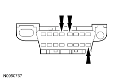 | Yes
GO to S2 . No REPAIR the DLC as necessary. CLEAR the DTCs. REPEAT the network test with the scan tool. |
| S2 CHECK THE DLC VOLTAGE SUPPLY CIRCUIT FOR AN OPEN | |
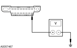 | Yes
GO to S3 . No VERIFY the Smart Junction Box (SJB) fuse 20 (15A) is OK. If OK, REPAIR the circuit. If not OK, REFER to the Wiring Diagrams manual to identify the possible causes of the circuit short. REPEAT the network test with the scan tool. |
| S3 CHECK THE DLC GROUND CIRCUITS FOR AN OPEN | |
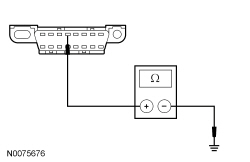 | Yes
REPAIR the scan tool. CONNECT the negative battery cable. REPEAT the network test with the scan tool. No REPAIR the circuit in question. CONNECT the negative battery cable. REPEAT the network test with the scan tool. |