
FLU77-4 or equivalent

SECTION 501-09: Rear View Mirrors
| 2014 Mustang Workshop Manual
|
DIAGNOSIS AND TESTING
| Procedure revision date: 01/07/2013
|
| Fluke 77-IV Digital Multimeter
FLU77-4 or equivalent |
|
Vehicle Communication Module (VCM) and Integrated Diagnostic System (IDS) software with appropriate hardware, or equivalent scan tool
|
Principles of Operation
Interior Auto-Dimming Rear View Mirror
The interior auto-dimming rear view mirror automatically reduces the glare caused by headlamps reflecting in the interior rear view mirror. The auto-dimming feature is disabled when the vehicle is in REVERSE. Power is supplied to the interior auto-dimming mirror when the ignition is in the RUN or ACC position.
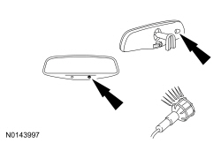
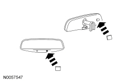
The interior auto-dimming rear view mirror has 2 photoelectric sensors that detect forward and rearward light conditions, and based on those inputs, adjusts the reflectance level of the interior rear view mirror to eliminate unwanted glare. The reflectance level of the mirror glass is variable and depends on the amount of rear glare in relation to ambient light conditions in front of the interior mirror.
When the forward sensor detects daytime conditions, the rearward sensor is inactive, and the mirror glass stays in a high reflectance mode. When the forward sensor detects nighttime conditions, the rearward sensor is active and detects glare from the headlights of vehicles approaching from the rear, or other glare producing light sources. To provide increased visibility when backing up, the interior rear view mirror glass will automatically return to a high reflectance mode whenever the selector lever is placed in REVERSE.
If the forward or rearward sensors are blocked, the auto-dimming interior rear view mirror might not work correctly.
Interior Rear View Mirror With Video Display
For vehicles that are equipped with a rear-mounted object detection camera, a video image will be displayed on the LH side of the interior rear view mirror glass when the transmission is in the REVERSE position. For information on the rear-mounted object detection system, refer to Section 413-13 .
Inspection and Verification
Visual Inspection Chart
| Mechanical | Electrical |
|---|---|
|
|
NOTE: Make sure to use the latest scan tool software release.
If the cause is not visually evident, connect the scan tool to the Data Link Connector (DLC).NOTE: The vehicle Vehicle Communication Module (VCM) LED prove-out confirms power and ground from the DLC are provided to the VCM .
If the scan tool does not communicate with the VCM :DTC Chart
Diagnostics in this manual assume a certain skill level and knowledge of Ford-specific diagnostic practices. REFER to Diagnostic Methods in Section 100-00 for more information about these practices.
Body Control Module B (BCM-B) DTC Chart
| DTC | Description | Action to Take |
|---|---|---|
| P0801:11 | Reverse Inhibit Control Circuit: Circuit Short to Ground | GO to Pinpoint Test D . |
| P0801:12 | Reverse Inhibit Control Circuit: Circuit Short to Battery | GO to Pinpoint Test D . |
| P0801:13 | Reverse Inhibit Control Circuit: Circuit Open | GO to Pinpoint Test D . |
| All other DTCs | — | REFER to Section 419-10 . |
Symptom Chart(s)
Diagnostics in this manual assume a certain skill level and knowledge of Ford-specific diagnostic practices. REFER to Diagnostic Methods in Section 100-00 for more information about these practices.
| Condition | Possible Sources | Action |
|---|---|---|
|
|
CLEAN the affected interior mirror surface. |
|
| |
|
|
|
|
| |
|
| |
| ||
|
|
|
|
|
|
| Condition | Possible Sources | Action |
|---|---|---|
|
|
|
Pinpoint Tests
Pinpoint Test D: The Auto-Dimming Mirror Does Not Operate Correctly
Diagnostics in this manual assume a certain skill level and knowledge of Ford-specific diagnostic practices. REFER to Diagnostic Methods in Section 100-00 for more information about these practices.
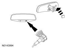
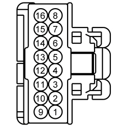
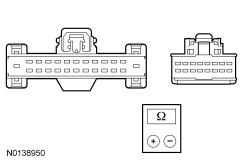
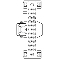
Refer to Wiring Diagrams Cell 124 , Power Mirrors for schematic and connector information.
The interior auto-dimming mirror receives voltage from Smart Junction Box (SJB) fuse 41 (15A) through circuit CBP41 (BU) and ground from circuit GD139 (BK/YE). When the selector lever is placed in REVERSE, voltage is sent to circuit CAT03 (GY/BN) from the Body Control Module B (BCM-B) and the interior auto-dimming mirror will turn the dimming feature off. There are 2 photoelectric sensors: one in front of the interior rear view mirror and one mounted on the glass side of the mirror. If the sensors are blocked, the interior mirror auto-dimming feature might not work correctly. Always verify both sensors are not physically blocked before attempting to diagnose auto-dimming mirror concerns.
| Test Step | Result / Action to Take | ||||||||||||||||||||||||||||||||
|---|---|---|---|---|---|---|---|---|---|---|---|---|---|---|---|---|---|---|---|---|---|---|---|---|---|---|---|---|---|---|---|---|---|
| D1 RETRIEVE THE DTCs FROM THE BCM-B | |||||||||||||||||||||||||||||||||
| Yes
For DTC P0801:11 or P0801:12, GO to D10 . For DTC P0801:13, GO to D11 . No GO to D2 . | ||||||||||||||||||||||||||||||||
| D2 VERIFY THE FORWARD AND REARWARD FACING SENSORS ARE NOT BLOCKED | |||||||||||||||||||||||||||||||||
| Yes
If possible, REMOVE the blockage. TEST the system for normal operation. If it is not possible to remove the blockage, REVIEW the operation of the interior auto-dimming mirror with the customer. No GO to D3 . | ||||||||||||||||||||||||||||||||
| D3 CHECK OPERATION OF THE INTERIOR AUTO-DIMMING MIRROR — DAYLIGHT CONDITIONS | |||||||||||||||||||||||||||||||||
 | Yes
GO to D4 . No INSTALL a new interior auto-dimming mirror. REFER to Interior Rear View Mirror in this section. TEST the system for normal operation. | ||||||||||||||||||||||||||||||||
| D4 CHECK THE OPERATION OF THE INTERIOR AUTO-DIMMING MIRROR — NIGHTTIME CONDITIONS WITHOUT GLARE | |||||||||||||||||||||||||||||||||
 | Yes
GO to D5 . No GO to D7 . | ||||||||||||||||||||||||||||||||
| D5 CHECK THE OPERATION OF THE INTERIOR AUTO-DIMMING MIRROR — NIGHTTIME CONDITIONS WITH GLARE | |||||||||||||||||||||||||||||||||
 | Yes
GO to D6 . No GO to D7 . | ||||||||||||||||||||||||||||||||
| D6 CHECK THE OPERATION OF THE INTERIOR AUTO-DIMMING MIRROR — NIGHTTIME CONDITIONS WITH VEHICLE IN REVERSE | |||||||||||||||||||||||||||||||||
| Yes
The system is operating correctly at this time. REVIEW operation of the interior auto-dimming interior mirror feature with the customer. No GO to D7 . | ||||||||||||||||||||||||||||||||
| D7 CHECK CIRCUIT CBP41 (BU) FOR VOLTAGE | |||||||||||||||||||||||||||||||||
 | Yes
GO to D8 . No VERIFY SJB fuse 41 (15A) is OK. If OK, REPAIR the circuit. If not OK, REFER to the Wiring Diagrams manual to identify the possible causes of the circuit short. | ||||||||||||||||||||||||||||||||
| D8 CHECK CIRCUIT GD139 (BK/YE) FOR AN OPEN | |||||||||||||||||||||||||||||||||
| Yes
GO to D9 . No REPAIR the circuit. | ||||||||||||||||||||||||||||||||
| D9 CHECK THE REVERSE INHIBIT CONTROL CIRCUIT FOR VOLTAGE | |||||||||||||||||||||||||||||||||
| Yes
INSTALL a new interior auto-dimming mirror. REFER to Interior Rear View Mirror in this section. No GO to D11 . | ||||||||||||||||||||||||||||||||
| D10 CHECK FOR DTCs IN THE BCM-B WITH THE INTERIOR MIRROR DISCONNECTED | |||||||||||||||||||||||||||||||||
| Yes
For DTC P0801:11, GO to D12 . For DTC P0801:12, GO to D13 . No INSTALL a new interior mirror. REFER to Interior Rear View Mirror in this section. | ||||||||||||||||||||||||||||||||
| D11 CHECK THE REVERSE INHIBIT CONTROL CIRCUIT FOR AN OPEN | |||||||||||||||||||||||||||||||||
 | Yes
GO to D14 . No REPAIR the circuit. | ||||||||||||||||||||||||||||||||
| D12 CHECK THE REVERSE INHIBIT CONTROL CIRCUIT FOR A SHORT TO GROUND | |||||||||||||||||||||||||||||||||
 | Yes
REPAIR the circuit. No GO to D14 . | ||||||||||||||||||||||||||||||||
| D13 CHECK THE REVERSE INHIBIT CONTROL CIRCUIT FOR A SHORT TO VOLTAGE | |||||||||||||||||||||||||||||||||
| Yes
REPAIR the circuit. No GO to D14 . | ||||||||||||||||||||||||||||||||
| D14 CHECK FOR CORRECT BCM-B OPERATION | |||||||||||||||||||||||||||||||||
| Yes
INSTALL a new BCM-B . REFER to Section 419-10 . No The system is operating correctly at this time. Concern may have been caused by a loose or corroded connector. | ||||||||||||||||||||||||||||||||