
105-R025D or equivalent

FLU77-4 or equivalent

software with appropriate hardware, or equivalent scan tool
SECTION 501-16: Wipers and Washers
| 2014 Mustang Workshop Manual
|
DIAGNOSIS AND TESTING
| Procedure revision date: 01/07/2013
|
| Flex Probe Kit
105-R025D or equivalent |
| Fluke 77-IV Digital Multimeter
FLU77-4 or equivalent |
| Vehicle Communication Module (VCM) and Integrated Diagnostic System (IDS)
software with appropriate hardware, or equivalent scan tool |
Principles of Operation
When the ignition switch is in the RUN or ACCESSORY position, voltage is supplied to the wiper relay coil at the Battery Junction Box (BJB). The wiper relay coil is grounded at all times. Voltage is supplied to the wiper relay switch from BJB fuse 9. When the wiper relay is activated, voltage is supplied to the wiper motor.
Wiper Activated Headlamps (if equipped with Autolamp System)
NOTE: The Smart Junction Box (SJB) may also be identified as the Generic Electronic Module (GEM).
The SJB sends a voltage signal to the wiper motor in order to monitor the status of the wipers. When the headlamp control switch is in the AUTOLAMP position and the wipers on, the SJB will activate the headlamps within 10 seconds. When the SJB detects that the wipers have been turned off, the SJB will turn off the headlamps after 30 seconds.
High-Speed Windshield Wipers
When the multifunction switch is set to the HIGH-speed position, it supplies ground to the internal high/low-speed relay coil and the internal run/park relay coil, which causes the windshield wiper motor to operate at high speed. During HIGH-speed operation only, both the internal high/low-speed relay coil ground and the internal run/park relay coil ground are controlled directly by the multifunction switch. This differs from LOW-speed or INTERMITTENT operation when the internal run/park relay coil is controlled by the microprocessor. When the switch is placed in the OFF position, the motor continues to operate until the motor returns to the PARK position and the internal Hall-effect sensor senses the motor magnet. The output to the internal run/park relay then deactivates the relay and disconnects the voltage to the motor.
Since the internal high/low relay coil and the internal run/park relay coil are both controlled by a hard-wired circuit to the multifunction switch, the windshield wipers will still operate in HIGH-speed mode if the internal windshield wiper module fails, but will not automatically park when the multifunction switch is turned to the OFF position.
Low-Speed Windshield Wipers
When the multifunction switch is set to the LOW-speed position, it supplies ground to the internal windshield wiper motor module low-speed input and the windshield wiper motor operates at low speed. During LOW-speed operation, the internal run/park relay is activated by the microprocessor and supplies 12 volts to the low-speed brush of the windshield wiper motor. The internal run/park relay coil ground is controlled by the internal windshield wiper motor module based on inputs received from the multifunction switch. When the switch is placed in the OFF position, the motor continues to operate until the motor returns to the PARK position and the internal Hall-effect sensor senses the motor magnet. The output to the internal run/park relay then deactivates the relay and disconnects the voltage to the motor.
Intermittent-Speed Windshield Wipers
When the multifunction switch is set to the INTERMITTENT position(s), it supplies ground to the windshield wiper motor module inputs and the windshield wiper motor operates in intermittent mode. During intermittent operation, the windshield wiper motor activates the internal run/park relay coil which sends voltage through the internal high/low relay. The internal high/low relay remains deactivated, supplying the voltage to the low-speed brush of the windshield wiper motor. The windshield motor continues to operate until the internal Hall-effect sensor senses the magnet (PARK position) and deactivates the internal run/park relay, which disconnects voltage from the wiper motor. The windshield wipers remain parked until the windshield wiper motor module completes a time-out and then repeats the intermittent windshield wiper cycle.
Washer System
The windshield washer system consists of the washer reservoir and washer pump. When WASH is selected on the multifunction switch, the windshield wiper motor module activates its integral washer relay which sends voltage to the washer pump to direct fluid to the windshield.
Software Safe Mode
The windshield wiper motor defaults to software safe mode when the run/park sensor does not sense the Hall-effect magnet inside the wiper motor. This can be caused by an obstruction of the windshield wipers, a binding linkage or loss of the Hall sensor signal. The motor continues to operate in a high/low-speed condition, and when turned off, the wipers immediately park on the windshield. If necessary, the wipers can be turned on and off until they return to the PARK position.
Windshield Wiper Circuit Function Table
| Multifunction Switch Position | Circuit CRW07 (GY/BN) | Circuit CRW08 (VT/OG) | Circuit CRW19 (BU/OG) | Circuit CRW18 (VT/WH) | Circuit CRW17 (GN/VT) |
|---|---|---|---|---|---|
| OFF | OPEN | OPEN | OPEN | OPEN | OPEN |
| INT 1 | OPEN | OPEN | OPEN | OPEN | GROUND |
| INT 2 | OPEN | OPEN | OPEN | GROUND | GROUND |
| INT 3 | OPEN | OPEN | OPEN | GROUND | OPEN |
| INT 4 | OPEN | OPEN | GROUND | GROUND | OPEN |
| INT 5 | OPEN | OPEN | GROUND | OPEN | OPEN |
| LOW | OPEN | OPEN | GROUND | OPEN | GROUND |
| HIGH | OPEN | GROUND | GROUND | OPEN | GROUND |
| WASH | GROUND | OPEN/GROUND | OPEN/GROUND | OPEN/GROUND | OPEN/GROUND |
Inspection and Verification
Visual Inspection Chart
| Mechanical | Electrical |
|---|---|
|
|
NOTE: The windshield wiper motor does not communicate on the network. The windshield wiper motor provides wiper on/off status directly to the SJB .
NOTE: Make sure to use the latest scan tool software release.
If the cause is not visually evident, connect the scan tool to the Data Link Connector (DLC).NOTE: The Vehicle Communication Module (VCM) LED prove out confirms power and ground from the DLC are provided to the VCM .
If the scan tool does not communicate with the VCM :DTC Chart
Smart Junction Box (SJB) DTC Chart
| DTC | Description | Action |
|---|---|---|
| B2008 | Wipers On Signal Circuit Short to Ground | GO to Pinpoint Test F . |
| All Other DTCs | — | REFER to the Master DTC Chart in Section 419-10 . |
Symptom Chart
| Condition | Possible Sources | Action |
|---|---|---|
|
| |
|
| |
|
| |
|
| |
|
|
|
|
| |
|
|
|
|
| |
|
|
Pinpoint Tests
Pinpoint Test A: The Wipers Are Inoperative
Refer to Wiring Diagrams Cell 81 , Wipers and Washers for schematic and connector information.
When the ignition switch is in the RUN or ACCESSORY position, voltage is supplied to the wiper relay coil through circuit CBP45 (YE). The wiper relay coil is grounded at all times through circuit GD129 (BK/YE). Voltage is supplied to the wiper relay switch through circuit SBB09 (RD). When the wiper relay is activated, voltage is supplied to the wiper motor through circuit CRW03 (VT/WH) and through CBP45 (YE) when the ignition switch is in the RUN or ACCESSORY position. The wiper motor is grounded through circuits GD129 (BK/YE) and GD123 (BK/GY). The multifunction switch is grounded through circuit GD116 (BK/VT). The multifunction switch sends open and ground input signals to the wiper motor through circuits CRW17 (GN/VT), CRW18 (VT/WH), CRW19 (BU/OG) and CRW08 (VT/OG) in order to activate the wiper motor to the requested modes.
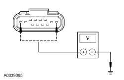
NOTICE: Use the correct probe adapter(s) from the Flex Probe Kit when making measurements. Failure to use the correct probe adapter(s) may damage the connector.
| Test Step | Result / Action to Take |
|---|---|
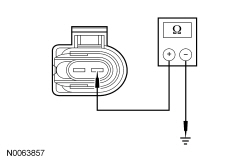
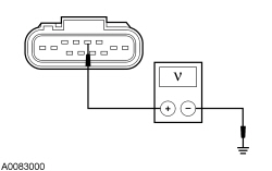
| A1 CHECK THE WINDSHIELD WIPER MOTOR FOR VOLTAGE | |
 | Yes
GO to A6 . No GO to A2 . |
| A2 CHECK THE WIPER RELAY | |
| Yes
GO to A3 . No INSTALL a new wiper relay. TEST the system for normal operation. |
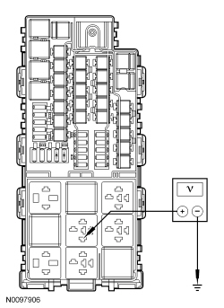
| A3 CHECK THE VOLTAGE TO THE WIPER RELAY COIL | |
 | Yes
GO to A4 . No VERIFY Smart Junction Box (SJB) fuse 45 (5A) is OK. If OK, REPAIR the circuit. If not OK, REFER to the Wiring Diagrams manual to identify the possible causes of the circuit short. TEST the system for normal operation. |
| A4 CHECK THE VOLTAGE TO THE WIPER RELAY SWITCH | |
 | Yes
GO to A5 . No VERIFY BJB fuse 9 (30A) is OK. If OK, REPAIR the circuit. If not OK, REFER to the Wiring Diagrams manual to identify the possible causes of the circuit short. TEST the system for normal operation. |
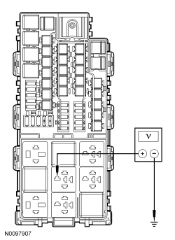
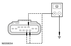
| A5 CHECK THE GROUND TO THE WIPER RELAY COIL | |
 | Yes
REPAIR open in circuit CRW03 (VT/WH). TEST the system for normal operation. No REPAIR open in circuit GD129 (BK/YE). TEST the system for normal operation. |
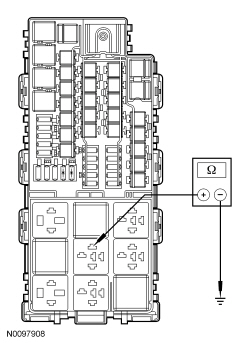
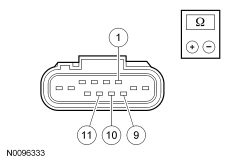
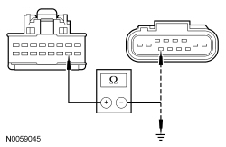
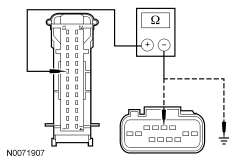
| A6 CHECK WIPER MOTOR CIRCUITS GD129 (BK/YE) AND GD123 (BK/GY) FOR AN OPEN | |
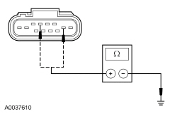 | Yes
GO to A7 . No REPAIR the circuit(s). TEST the system for normal operation. |
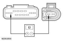
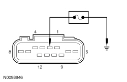
| A7 CHECK THE MULTIFUNCTION SWITCH | |
| Yes
GO to A8 . No INSTALL a new multifunction switch. REFER to Section 211-05 . |
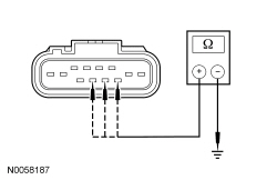
| A8 CHECK CIRCUIT GD116 (BK/VT) FOR AN OPEN | |
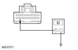 | Yes
GO to A9 . No REPAIR the circuit. TEST the system for normal operation. |
| A9 CHECK FOR CORRECT WIPER MOTOR OPERATION | |
| Yes
INSTALL a new wiper motor. REFER to Wiper Motor in this section. No The system is operating correctly at this time. Concern may have been caused by a loose or corroded connector. TEST the system for normal operation. |
Pinpoint Test B: The Wipers Stay On Continuously
Refer to Wiring Diagrams Cell 81 , Wipers and Washers for schematic and connector information.
Under normal operation, the windshield wiper motor receives open and ground inputs from the multifunction switch through circuits CRW17 (GN/VT), CRW18 (VT/WH), CRW19 (BU/OG) and CRW08 (VT/OG) to activate the wipers to the appropriate modes. Mode of operation is dependent on the signal(s) received from the multifunction switch.
NOTICE: Use the correct probe adapter(s) from the Flex Probe Kit when making measurements. Failure to use the correct probe adapter(s) may damage the connector.
| Test Step | Result / Action to Take |
|---|---|
| B1 CHECK THE MULTIFUNCTION SWITCH | |
| Yes
GO to B2 . No INSTALL a new multifunction switch. REFER to Section 211-05 . |
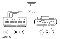
| B2 CHECK CIRCUITS CRW19 (BU/OG), CRW18 (VT/WH), CRW08 (VT/OG) AND CRW17 (GN/VT) FOR A SHORT TO GROUND | |
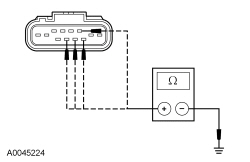 | Yes
GO to B3 . No REPAIR the circuit(s) in question. TEST the system for normal operation. |
| B3 CHECK FOR CORRECT WIPER MOTOR OPERATION | |
| Yes
INSTALL a new windshield wiper motor. REFER to Wiper Motor in this section. No The system is operating correctly at this time. Concern may have been caused by a loose or corroded connector. TEST the system for normal operation. |
Pinpoint Test C: The High/Low Wiper Speeds Do Not Operate Correctly
Refer to Wiring Diagrams Cell 81 , Wipers and Washers for schematic and connector information.
Under normal operation, the windshield wiper motor receives open and ground inputs from the multifunction switch through circuits CRW17 (GN/VT), CRW18 (VT/WH), CRW19 (BU/OG) and CRW08 (VT/OG) to activate the wipers to the appropriate modes. Mode of operation is dependent on the signal(s) received from the multifunction switch.
NOTICE: Use the correct probe adapter(s) from the Flex Probe Kit when making measurements. Failure to use the correct probe adapter(s) may damage the connector.
| Test Step | Result / Action to Take | |||||||||||||||||||||
|---|---|---|---|---|---|---|---|---|---|---|---|---|---|---|---|---|---|---|---|---|---|---|
| C1 CHECK THE MULTIFUNCTION SWITCH | ||||||||||||||||||||||
| Yes
GO to C2 . No INSTALL a new multifunction switch. REFER to Section 211-05 . TEST the system for normal operation. | |||||||||||||||||||||
| C2 CHECK CIRCUITS CRW19 (BU/OG), CRW08 (VT/OG) AND CRW17 (GN/VT) FOR AN OPEN | ||||||||||||||||||||||
 | Yes
GO to C3 . No REPAIR the circuit(s) in question. TEST the system for normal operation. | |||||||||||||||||||||
| C3 CHECK CIRCUITS CRW19 (BU/OG), CRW08 (VT/OG) AND CRW17 (GN/VT) FOR A SHORT TO GROUND | ||||||||||||||||||||||
 | Yes
GO to C4 . No REPAIR the circuit(s) in question. TEST the system for normal operation. | |||||||||||||||||||||
| C4 CHECK FOR SHORTS IN THE WINDSHIELD WIPER MOTOR HARNESS | ||||||||||||||||||||||
 | Yes
GO to C5 . No REPAIR the circuit. TEST the system for normal operation. | |||||||||||||||||||||
| C5 CHECK FOR CORRECT WIPER MOTOR OPERATION | ||||||||||||||||||||||
| Yes
INSTALL a new windshield wiper motor. REFER to Wiper Motor in this section. No The system is operating correctly at this time. Concern may have been caused by a loose or corroded connector. TEST the system for normal operation. |
Pinpoint Test D: The Intermittent Wiper Speed Does Not Operate Correctly
Refer to Wiring Diagrams Cell 81 , Wipers and Washers for schematic and connector information.
Under normal operation, the windshield wiper motor receives open and ground inputs from the multifunction switch through circuits CRW17 (GN/VT), CRW18 (VT/WH), CRW19 (BU/OG) and CRW08 (VT/OG) to activate the wipers to the appropriate modes. Mode of operation is dependent on the signal(s) received from the multifunction switch.
NOTICE: Use the correct probe adapter(s) from the Flex Probe Kit when making measurements. Failure to use the correct probe adapter(s) may damage the connector.
| Test Step | Result / Action to Take | |||||||||||||||||||||
|---|---|---|---|---|---|---|---|---|---|---|---|---|---|---|---|---|---|---|---|---|---|---|
| D1 CHECK THE MULTIFUNCTION SWITCH | ||||||||||||||||||||||
| Yes
GO to D2 . No INSTALL a new multifunction switch. REFER to Section 211-05 . TEST the system for normal operation. | |||||||||||||||||||||
| D2 CHECK CIRCUITS CRW19 (BU/OG), CRW18 (VT/WH) AND CRW17 (GN/VT) FOR AN OPEN | ||||||||||||||||||||||
 | Yes
GO to D3 . No REPAIR the circuit(s) in question. TEST the system for normal operation. | |||||||||||||||||||||
| D3 CHECK CIRCUITS CRW19 (BU/OG), CRW18 (VT/WH) AND CRW17 (GN/VT) FOR A SHORT TO GROUND | ||||||||||||||||||||||
 | Yes
GO to D4 . No REPAIR the circuit(s) in question. TEST the system for normal operation. | |||||||||||||||||||||
| D4 CHECK FOR SHORTS IN THE WINDSHIELD WIPER MOTOR HARNESS | ||||||||||||||||||||||
| Yes
GO to D5 . No REPAIR the circuit. TEST the system for normal operation. | |||||||||||||||||||||
| D5 CHECK FOR CORRECT WIPER MOTOR OPERATION | ||||||||||||||||||||||
| Yes
INSTALL a new windshield wiper motor. REFER to Wiper Motor in this section. No The system is operating correctly at this time. Concern may have been caused by a loose or corroded connector. TEST the system for normal operation. |
Pinpoint Test E: The Washer Pump is Inoperative
Refer to Wiring Diagrams Cell 81 , Wipers and Washers for schematic and connector information.
During normal operation, the windshield wiper motor receives voltage through Battery Junction Box (BJB) fuse 9 (30A), circuit SBB09 (RD) and through Smart Junction Box (SJB) fuse 45 (5A), circuit CBP45 (YE) when the ignition switch is in the RUN or ACC positions. Ground is provided to the windshield wiper motor through circuits GD129 (BK/YE) and GD123 (BK/GY). The internal run/park and internal high/low relays are contained in the wiper motor electronics. Mode of operation is dependent on the signal(s) received from the multifunction switch. When the correct input is received from the multifunction switch, the windshield wiper motor activates the washer pump by providing power through circuit CRW14 (BU/WH). Ground is provided to the washer pump through circuit GD123 (BK/GY).
NOTICE: Use the correct probe adapter(s) from the Flex Probe Kit when making measurements. Failure to use the correct probe adapter(s) may damage the connector.
| Test Step | Result / Action to Take |
|---|---|
| E1 CHECK CIRCUIT GD123 (BK/GY) FOR AN OPEN | |
 | Yes
GO to E2 . No REPAIR the circuit. TEST the system for normal operation. |
| E2 CHECK CIRCUIT CRW14 (BU/WH) FOR VOLTAGE | |
 | Yes
INSTALL a new washer pump. REFER to Washer Pump and Reservoir in this section. No GO to E3 . |
| E3 CHECK THE MULTIFUNCTION SWITCH | |
| Yes
GO to E4 . No INSTALL a new multifunction switch. REFER to Section 211-05 . |
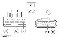
| E4 CHECK CIRCUIT CRW07 (GY/BN) FOR AN OPEN | |
 | Yes
GO to E5 . No REPAIR the circuit. TEST the system for normal operation. |
| E5 CHECK CIRCUIT CRW14 (BU/WH) FOR AN OPEN | |
 | Yes
GO to E6 . No REPAIR the circuit. TEST the system for normal operation. |
| E6 CHECK FOR CORRECT WIPER MOTOR OPERATION | |
| Yes
INSTALL a new windshield wiper motor. REFER to Wiper Motor in this section. No The system is operating correctly at this time. Concern may have been caused by a loose or corroded connector. TEST the system for normal operation. |
Pinpoint Test F: The Headlamps Do Not Illuminate When the Wipers are On
The Smart Junction Box (SJB) monitors the status of the wipers through circuit CRW01 (WH). When the headlamp control switch is in the AUTOLAMP position and the wipers are on, the wiper motor module will pull the voltage reference signal low. Within 10 seconds, the SJB will activate the headlamps.
NOTICE: Use the correct probe adapter(s) from the Flex Probe Kit when making measurements. Failure to use the correct probe adapter(s) may damage the connector.
| Test Step | Result / Action to Take |
|---|---|
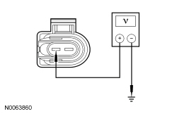
| F1 CHECK THE WIPER MOTOR ON INPUT VOLTAGE TO THE WINDSHIELD WIPER MOTOR | |
 | Yes
GO to F3 . No GO to F2 . |
| F2 CHECK CIRCUIT CRW01 (WH) FOR AN OPEN OR SHORT TO GROUND | |
 | Yes
GO to F4 . No REPAIR the circuit. CLEAR the DTCs. REPEAT the self-test. |
| F3 CHECK THE WIPER ACTIVATED HEADLAMPS OPERATION | |
 | Yes
INSTALL a new wiper motor. REFER to Wiper Motor in this section. CLEAR the DTCs. REPEAT the self-test. No GO to F4 . |
| F4 CHECK FOR CORRECT MODULE OPERATION | |
| Yes
INSTALL a new SJB . REFER to Section 419-10 . CLEAR the DTCs. REPEAT the self-test. No The system is operating correctly at this time. Concern may have been caused by a loose or corroded connector. CLEAR the DTCs. REPEAT the self-test. |