286-00002

286-00001
SECTION 501-35: Body Repairs
| 2014 Mustang Workshop Manual
|
REMOVAL AND INSTALLATION
| Procedure revision date: 01/07/2013
|
| Rust Inhibitor Installation Kit
286-00002 |
| Undercoating Spray Gun
286-00001 |
| 3 Phase Inverter Spot Welder 254-00002 |
| Compuspot 700F Welder 190-50080 |
| I4 Inverter Spot Welder 254-000014 |
| Inverter Welder with MIG Welder 254-00015 |
| Item | Specification |
|---|---|
| Motorcraft® Metal Surface Prep
ZC-31-A | — |
| Premium Undercoating
ValuGard™ VG101, VG101A (aerosol) | — |
| Rust Inhibitor
ValuGard™ VG104, VG104A (aerosol) | — |
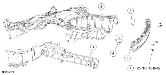
| Item | Part Number | Description |
|---|---|---|
| 1 | 10457 LH/ 10456 RH | Rear floor side member — High-Strength Low Alloy (HSLA) 350 steel |
| 2 | — | Underbody assembly mild and High-Strength Steel (HSS) steel |
| 3 | 17A751 | Rear bumper mounting bracket — HSLA 350 steel |
| 4 | W711097 | Rear bumper bolt (6 required) |
| 5 | 17906 | Rear bumper — boron steel |
| 6 | 17A750 | Rear bumper mounting bracket — HSLA 350 steel |
 WARNING: Collision damage repair must conform to the instructions contained in this workshop manual. Replacement components must be new, genuine Ford Motor Company parts. Recycled, salvaged, aftermarket or reconditioned parts (including body parts, wheels or safety restraint components) are not authorized by Ford.
Departure from the instructions provided in this manual, including alternate repair methods or the use of substitute components, risks compromising crash safety. Failure to follow these instructions may adversely affect structural integrity and crash safety performance, which could result in serious personal injury to vehicle occupants in a crash.
WARNING: Invisible ultraviolet and infrared rays emitted in welding can injure unprotected eyes and skin. Always use protection such as a welder's helmet with dark-colored filter lenses of the correct density. Electric welding will produce intense radiation, therefore, filter plate lenses of the deepest shade providing adequate visibility are recommended. It is strongly recommended that persons working in the weld area wear flash safety goggles. Also wear protective clothing. Failure to follow these instructions may result in serious personal injury.
WARNING: Always wear protective equipment including eye protection with side shields, and a dust mask when sanding or grinding. Failure to follow these instructions may result in serious personal injury.
NOTE: Refer to welding equipment manufacturer's instructions for correct machine set up.
NOTE: All body alignment measurements are carried out with the vehicle detrimmed. Measurements are made metal to metal, on center, unless otherwise specified.
Measure the vehicle to determine if the body requires straightening and alignment. The vehicle must be restored to its correct overall dimensions prior to beginning this procedure. For body dimensional information, refer to Body in this section.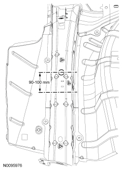
NOTE: DO NOT drill pilot holes in an attempt to aid in spot weld removal.
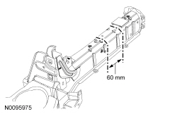
Drill out the spot welds attaching the frame rail to the underbody using a spot weld cutter or equivalent tool, and remove the damaged section.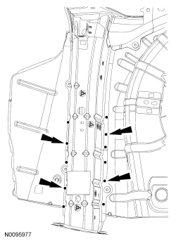
Installation