SECTION 303-01A: Engine — 3.7L
| 2014 Mustang Workshop Manual
|
IN-VEHICLE REPAIR
| Procedure revision date: 01/07/2013
|
Cylinder Head — RH
Material
| Item
| Specification
|
|---|
Motorcraft® SAE 5W-20 Premium Synthetic Blend Motor Oil (US); Motorcraft® SAE 5W-20 Super Premium Motor Oil (Canada)
XO-5W20-QSP (US); CXO-5W20-LSP12 (Canada)
| WSS-M2C945-A
|
| Item
| Part Number
| Description
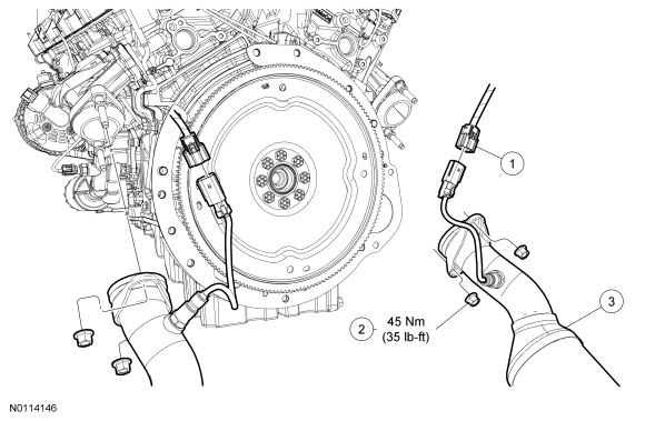
| | 1
| —
| Heated Oxygen Sensor (HO2S) electrical connector (part of 12C508) (2 required)
|
| 2
| W714265
| Catalytic converter-to-exhaust manifold nuts (4 required)
|
| 3
| 5F250
| Catalytic converter assembly (Y-pipe)
|
| Item
| Part Number
| Description
| | 1
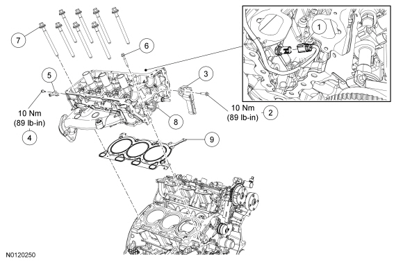
| —
| Cylinder Head Temperature (CHT) sensor electrical connector (part of 12A581)
|
| 2
| W715118
| RH primary timing chain guide bolt
|
| 3
| 6K297
| RH primary timing chain guide
|
| 4
| W503275
| Ground wire bolt
|
| 5
| —
| Ground wire (part of 14300)
|
| 6
| W710702
| Cylinder head M6 bolt
|
| 7
| 6065
| Cylinder head bolt (8 required)
|
| 8
| 6049
| Cylinder head
|
| 9
| 6051
| Cylinder head gasket
|
Removal
 WARNING: Do not smoke, carry lighted tobacco or have an open flame of any type when working on or near any fuel-related component. Highly flammable mixtures are always present and may be ignited. Failure to follow these instructions may result in serious personal injury.
WARNING: Before working on or disconnecting any of the fuel tubes or fuel system components, relieve the fuel system pressure to prevent accidental spraying of fuel. Fuel in the fuel system remains under high pressure, even when the engine is not running. Failure to follow this instruction may result in serious personal injury.
WARNING: Do not carry personal electronic devices such as cell phones, pagers or audio equipment of any type when working on or near any fuel-related component. Highly flammable mixtures are always present and may be ignited. Failure to follow these instructions may result in serious personal injury.
WARNING: Always disconnect the battery ground cable at the battery when working on an evaporative emission (EVAP) system or fuel-related component. Highly flammable mixtures are always present and may be ignited. Failure to follow these instructions may result in serious personal injury.
WARNING: Clean all fuel residue from the engine compartment. If not removed, fuel residue may ignite when the engine is returned to operation. Failure to follow this instruction may result in serious personal injury.
NOTICE:
During engine repair procedures, cleanliness is extremely important. Any foreign material, including any material created while cleaning gasket surfaces that enters the oil passages, coolant passages or the oil pan, may cause engine failure.
NOTE:
If the cylinder head is replaced, a new secondary timing chain tensioner will need to be installed.
- Release the fuel system pressure. For additional information, refer to
Section 310-00
.
- Disconnect the battery ground cable. For additional information, refer to
Section 414-01
.
- Detach and disconnect the RH and LH Heated Oxygen Sensor (HO2S) electrical connectors.
- Remove and discard the LH and RH catalytic converter-to-exhaust manifold nuts and lower the catalytic converter assembly.
- Remove the RH camshafts. For additional information, refer to
Camshaft — RH
in this section.
- Remove the lower intake manifold. For additional information, refer to
Lower Intake Manifold
in this section.
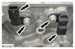
- Disconnect the Cylinder Head Temperature (CHT) sensor electrical connector.
NOTICE:
Do not use power tools to remove the bolt or damage to the RH primary timing chain guide may occur.
Remove the bolt and the RH primary timing chain guide.
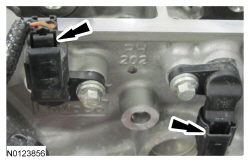
- Disconnect the 2 RH Camshaft Position (CMP) sensors electrical connectors.
- Remove the 2 bolts and the 2 RH
sensors.
- Remove the bolt and ground wire from the rear of the RH cylinder head.
NOTE:
If the components are to be reinstalled, they must be installed in the same positions. Mark the components for installation into their original locations.
Remove the valve tappets from the cylinder head.
- Inspect the valve tappets. For additional information, refer to
Section 303-00
.
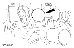
- Remove and discard the M6 bolt.
NOTICE:
Place clean, lint-free shop towels over exposed engine cavities. Carefully remove the towels so foreign material is not dropped into the engine. Any foreign material (including any material created while cleaning gasket surfaces) that enters the oil passages or the oil pan, may cause engine failure.
NOTICE:
Aluminum surfaces are soft and may be scratched easily. Never place the cylinder head gasket surface, unprotected, on a bench surface.
NOTE:
The cylinder head bolts must be discarded and new bolts must be installed. They are a tighten-to-yield design and cannot be reused.
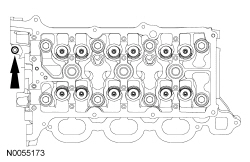
Remove and discard the 8 bolts from the cylinder head.
- Remove the cylinder head.
- Discard the cylinder head gasket.
NOTICE:
Do not use metal scrapers, wire brushes, power abrasive discs or other abrasive means to clean the sealing surfaces. These tools cause scratches and gouges that make leak paths. Use a plastic scraping tool to remove all traces of the head gasket.
NOTE:
Observe all warnings or cautions and follow all application directions contained on the packaging of the silicone gasket remover and the metal surface prep.
NOTE:
If there is no residual gasket material present, metal surface prep can be used to clean and prepare the surfaces.
Clean the cylinder head-to-cylinder block mating surfaces of both the cylinder heads and the cylinder block in the following sequence.
- Remove any large deposits of silicone or gasket material with a plastic scraper.
- Apply silicone gasket remover, following package directions, and allow to set for several minutes.
- Remove the silicone gasket remover with a plastic scraper. A second application of silicone gasket remover may be required if residual traces of silicone or gasket material remain.
- Apply metal surface prep, following package directions, to remove any remaining traces of oil or coolant and to prepare the surfaces to bond with the new gasket. Do not attempt to make the metal shiny. Some staining of the metal surfaces is normal.
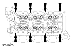
- Support the cylinder head on a bench with the head gasket side up. Check the cylinder head distortion and the cylinder block distortion. For additional information, refer to
Section 303-00
.
Installation
NOTE:
If the cylinder head is replaced, a new secondary timing chain tensioner will need to be installed.
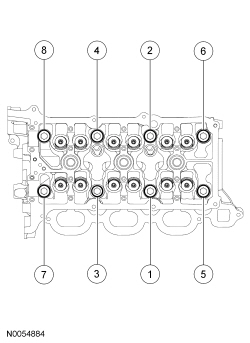
Install a new gasket, the RH cylinder head and 8 new bolts. Tighten in the sequence shown in 5 stages:
- Stage 1: Tighten to 20 Nm (177 lb-in).
- Stage 2: Tighten to 35 Nm (26 lb-ft).
- Stage 3: Tighten 90 degrees.
- Stage 4: Tighten 90 degrees.
- Stage 5: Tighten 45 degrees.
- Install the M6 bolt.
- Tighten to 10 Nm (89 lb-in).
NOTE:
The valve tappets must be installed in their original positions.
NOTE:
Coat the valve tappets with clean engine oil prior to installation.
Install the valve tappets.
- Install the ground wire and bolt to the rear of the RH cylinder head.
- Tighten to 10 Nm (89 lb-in).
NOTE:
Lubricate the 2
sensor O-ring seals with clean engine oil.
Install the 2 RH
sensors and the 2 bolts.
- Tighten to 10 Nm (89 lb-in).
- Connect the 2 RH
sensors electrical connectors.
- Install the RH primary timing chain guide and the bolt.
- Tighten to 10 Nm (89 lb-in).
- Connect the
sensor electrical connector.
- Install the lower intake manifold. For additional information, refer to
Lower Intake Manifold
in this section.
- Install the RH camshafts. For additional information, refer to
Camshaft — RH
in this section.
- Raise the catalytic converter and install the new LH and RH catalytic converter-to-exhaust manifold nuts.
- Tighten to 45 Nm (35 lb-ft).
- Connect and attach the RH and LH
electrical connectors.
- Connect the battery ground cable. For additional information, refer to
Section 414-01
.