
328-2050-62291 or equivalent

300-ROB75240 or equivalent

300-OTC-014-R1068

STN12270 or equivalent

UVU560000-R or equivalent

SECTION 303-03A: Engine Cooling
| 2014 Mustang Workshop Manual
|
DIAGNOSIS AND TESTING
| Procedure revision date: 01/07/2013
|
| 3-Way HD Antifreeze Coolant Test Kit
328-2050-62291 or equivalent |
| Coolant/Battery Refractometer
300-ROB75240 or equivalent |
| D-Gas Adapter
300-OTC-014-R1068 |
| Radiator Tester
STN12270 or equivalent |
| UView® Combustion Leak Tester
UVU560000-R or equivalent |
| Vehicle Communication Module (VCM) and Integrated Diagnostic System (IDS) software with appropriate hardware or equivalent scan tool
|
| Item | Specification |
|---|---|
| Motorcraft® Orange Antifreeze/Coolant Concentrated
VC-3-B (US); CVC-3-B2 (Canada) | WSS-M97B44-D |
| Motorcraft® Orange Antifreeze/Coolant Prediluted
VC-3DIL-B (US); CVC-3DIL-B (Canada) | WSS-M97B44-D2 |
Principles of Operation
Engine coolant flows primarily from the engine to the radiator circuit and back to the coolant pump. Coolant is sent from the coolant pump through the engine block and cylinder heads. A separate circuit from the engine also feeds the heater core with coolant. The coolant pump is operated by engine rotation through the accessory drive belt pulley. The coolant thermostat is a control valve actuated by coolant temperature. When the thermostat is closed, coolant flow bypasses the radiator circuit and returns to the coolant pump. When the thermostat is opened, coolant flows through the radiator circuit to transfer engine-generated heat to the outside air.
The degas bottle removes air from the cooling system, allows for coolant expansion and system pressurization, replenishes coolant to the cooling system and serves as the location for service fill.
The cooling fan draws air through the radiator to help cool the system coolant as it passes through the radiator.
The thermostat monitor is a function of the PCM and is designed to verify correct thermostat operation. The monitor executes once per drive cycle and has a monitor run duration of 300-800 seconds. If a malfunction occurs, DTC P0125 or P0128 is set and the MIL is illuminated.
For engine specific information, refer to Engine Cooling .
Inspection and Verification
 WARNING: Always allow the engine to cool before opening the cooling system. Do not unscrew the coolant pressure relief cap when the engine is operating or the cooling system is hot. The cooling system is under pressure; steam and hot liquid can come out forcefully when the cap is loosened slightly. Failure to follow these instructions may result in serious personal injury.
NOTICE: The engine cooling system is filled with Motorcraft® Orange Antifreeze/Coolant. Do not mix coolant types. Mixing coolant types degrades the corrosion protection of Motorcraft® Orange Antifreeze/Coolant. Failure to follow these instructions may damage the engine or cooling system.
NOTICE: Always fill the cooling system with the manufacturer's specified coolant. Chemically flush the cooling system if a non-specified coolant has been used. Refer to Cooling System Flushing . Failure to follow these instructions may damage the engine or cooling system.
NOTE: During normal vehicle operation, Motorcraft Orange Antifreeze/Coolant may change color from orange to pink or light red. As long as the engine coolant is clear and uncontaminated, this color change does not indicate the engine coolant has degraded nor does it require the engine coolant to be drained, the system to be flushed, or the engine coolant to be replaced.
NOTE: Vehicles have the pressure relief cap on the degas bottle and no radiator cap.
NOTE: Take note of any coolant odor or steam coming from cooling system components.
If the engine coolant is filled correctly and no DTCs associated with fail-safe cooling are retrieved, verify the customer's concern by operating the engine to duplicate the condition.NOTE: For the coolant flow diagram, refer to Engine Cooling .
Visually inspect for obvious signs of any mechanical or electrical damage.Visual Inspection Chart
| Mechanical | Electrical |
|---|---|
|
|
|
NOTE: Make sure to use the latest scan tool software release.
If the cause is not visually evident, connect the scan tool to the Data Link Connector (DLC).NOTE: The Vehicle Communication Module (VCM) LED prove-out confirms power and ground from the DLC are provided to the VCM .
If the scan tool does not communicate with the VCM :DTC Chart
PCM DTC Chart
| DTC | Description | Action |
|---|---|---|
| P0217 | Engine Coolant Overtemperature Condition | GO to Pinpoint Test B . |
| P1285 | Cylinder Head Overtemperature Condition | GO to Pinpoint Test B . |
| P1299 | Cylinder Head Overtemperature Protection Active | GO to Pinpoint Test B . |
| P0125 | Insufficient Coolant Temp For Closed Loop Fuel Control | GO to Pinpoint Test C . |
| P0128 | Coolant Thermostat (Coolant Temp Below Thermostat Regulating Temperature) | GO to Pinpoint Test C . |
| P0480
P0481 P0482 | Fan 1, 2 or 3 Control Circuit, Respectively | REFER to the Powertrain Control/Emissions Diagnosis (PC/ED) manual. |
| All Other PCM DTCs | — | REFER to Section 303-14 . |
Symptom Chart
| Condition | Possible Sources | Action |
|---|---|---|
|
| |
|
| |
|
| |
|
|
|
|
| |
|
|
|
|
|
|
|
|
|
|
|
Pinpoint Tests
Pinpoint Test A: Loss of Coolant
The engine cooling system is a closed system providing for coolant expansion and contraction as well as changes in pressure as coolant warms and cools with engine operation. Various gaskets, seals, hoses and clamps contain coolant within the cooling system and keep other fluids and contaminants from entering the cooling system.
Coolant loss can be attributed to external or internal leaks anywhere within the cooling system.
For engine specific information, refer to Engine Cooling .
WARNING: Always allow the engine to cool before opening the cooling system. Do not unscrew the coolant pressure relief cap when the engine is operating or the cooling system is hot. The cooling system is under pressure; steam and hot liquid can come out forcefully when the cap is loosened slightly. Failure to follow these instructions may result in serious personal injury.
| Test Step | Result / Action to Take |
|---|---|
| A1 CARRY OUT INSPECTION AND VERIFICATION | |
| Yes
REPAIR as needed. TEST the system for normal operation. No GO to A2 . |
| A2 CHECK THE ENGINE COOLANT LEVEL | |
NOTE: Allow the engine to cool before checking the engine coolant level. | Yes
GO to A3 . No ADJUST the engine coolant level as necessary. GO to A3 . |
| A3 PRESSURE TEST THE ENGINE COOLING SYSTEM | |
| Yes
REPAIR or INSTALL new components. TEST the system for normal operation. No GO to A4 . |
| A4 CHECK THE ENGINE COOLANT FOR AN INTERNAL LEAK | |
| Yes
GO to Section 303-00 for engine diagnosis. No GO to A5 . |
| A5 CHECK THE ENGINE OIL FOR COOLANT | |
| Yes
GO to Section 303-00 for engine diagnosis. No GO to A6 . |
| A6 CHECK THE COOLING SYSTEM FOR COMBUSTION GASES | |
| Yes
GO to Section 303-00 for engine diagnosis. No The cooling system is operational. |
Pinpoint Test B: The Engine Overheats
The engine cooling system maintains the engine temperature during operation. Correct coolant flow through the engine, radiator and remainder of cooling system passages and components is essential to maintaining a correct engine temperature.
Engine coolant flows primarily from the engine to the radiator circuit and back to the coolant pump. Coolant is sent from the coolant pump through the engine block and cylinder heads. A separate circuit from the engine also feeds the heater core with coolant. The coolant pump, operated by engine rotation through the accessory drive belt pulley, circulates the coolant. The coolant thermostat is a control valve actuated by coolant temperature. When the thermostat is closed, coolant flow bypasses the radiator circuit and returns to the coolant pump. When the thermostat is opened, coolant flows through the radiator circuit to transfer engine-generated heat to the outside air.
Engine overheating generally occurs when there is a disruption in the ability to control either coolant flow at the correct rate, the inability to transfer heat from the engine through the coolant (including low coolant) or an inability to transfer engine-generated heat to the outside air through the radiator.
For engine specific information, refer to Engine Cooling .
WARNING: Always allow the engine to cool before opening the cooling system. Do not unscrew the coolant pressure relief cap when the engine is operating or the cooling system is hot. The cooling system is under pressure; steam and hot liquid can come out forcefully when the cap is loosened slightly. Failure to follow these instructions may result in serious personal injury.
| Test Step | Result / Action to Take |
|---|---|
| B1 CARRY OUT INSPECTION AND VERIFICATION | |
| Yes
REPAIR as needed. TEST the system for normal operation. No GO to B2 . |
| B2 CHECK FOR PCM DTCs | |
| Yes
GO to B3 . No Actual engine overheating has not been verified. CHECK the engine temperature gauge operation. REFER to Section 413-01 . If any other DTCs are retrieved, REFER to Section 303-14 . |
| B3 CHECK FOR AN AIRFLOW OBSTRUCTION | |
| Yes
REMOVE the obstruction. TEST the system for normal operation. No GO to B4 . |
| B4 CHECK THE ENGINE COOLANT LEVEL | |
NOTE: Allow the engine to cool before checking the engine coolant level. | Yes
GO to B5 . No ADJUST the engine coolant level as necessary. GO to B5 . |
| B5 PRESSURE TEST THE ENGINE COOLING SYSTEM | |
| Yes
REPAIR or INSTALL new components. TEST the system for normal operation. No GO to B6 . |
| B6 CHECK THE ENGINE COOLANT FOR AN INTERNAL LEAK | |
| Yes
GO to Section 303-00 for engine diagnosis. No GO to B7 . |
| B7 CHECK THE ENGINE OIL FOR COOLANT | |
| Yes
GO to Section 303-00 for engine diagnosis. No GO to B8 . |
| B8 CHECK THE COOLING SYSTEM FOR COMBUSTION GASES | |
| Yes
GO to Section 303-00 for engine diagnosis. No GO to B9 . |
| B9 CHECK COOLANT CONDITION | |
| Yes
GO to B10 . No FLUSH the engine cooling system. REFER to Cooling System Flushing . TEST the system for normal operation. |
| B10 CHECK THE ELECTRIC COOLING FAN OPERATION | |
| Yes
GO to B11 . No DIAGNOSE the electric cooling fan operation. REFER to Powertrain Control/Emissions Diagnosis (PC/ED) manual. |
| B11 CHECK THE COOLANT PUMP OPERATION | |
| Yes
GO to B12 . No INSTALL a new coolant pump. TEST the system for normal operation. |
| B12 CHECK THE THERMOSTAT OPERATION | |
| Yes
CHECK the engine temperature gauge operation. REFER to Section 413-01 . No GO to B13 . |
| B13 VISUALLY INSPECT THE THERMOSTAT | |
| Yes
INSTALL a new thermostat. TEST the system for normal operation. No INSTALL a new thermostat. TEST the system for normal operation. If the engine still overheats, INSTALL a new radiator. TEST the system for normal operation. |
Pinpoint Test C: The Engine Does Not Reach Normal Operating Temperature
The engine cooling system maintains engine temperature during operation. Correct coolant flow through the engine, radiator and remainder of cooling system passages and components is essential to maintaining a correct engine temperature.
Engine coolant flows primarily from the engine to the radiator circuit and back to the coolant pump. Coolant is sent from the coolant pump through the engine block and cylinder heads. A separate circuit from the engine also feeds the heater core with coolant. The coolant pump, operated by engine rotation through the accessory drive belt pulley, circulates the coolant. The coolant thermostat is a control valve actuated by coolant temperature. When the thermostat is closed, coolant flow bypasses the radiator circuit and returns to the coolant pump. When the thermostat is opened, coolant flows through the radiator circuit to transfer engine generated heat to the outside air.
Concerns of engine inability to reach normal operating temperature typically occur when the rate of coolant flow through some coolant circuits (radiator, heater core) is more than expected given the conditions, or when the cooling fans operate all of the time. Heat is not allowed to build in the engine because a heat exchanger is removing too much heat, including the radiator, heater core and engine oil cooler (5.8L engine). In addition, perceived concerns that the engine does not reach normal operating temperature can be related to a low coolant level or trapped air which does not allow for hot coolant to be available at the heater core, an inoperative climate control system, or for concerns perceived or related to an incorrect engine temperature gauge indication.
For vehicle/engine specific information, refer to Engine Cooling .
WARNING: Always allow the engine to cool before opening the cooling system. Do not unscrew the coolant pressure relief cap when the engine is operating or the cooling system is hot. The cooling system is under pressure; steam and hot liquid can come out forcefully when the cap is loosened slightly. Failure to follow these instructions may result in serious personal injury.
| Test Step | Result / Action to Take |
|---|---|
| C1 CARRY OUT INSPECTION AND VERIFICATION | |
| Yes
REPAIR as needed. TEST the system for normal operation. No GO to C2 . |
| C2 CHECK FOR DTC P0125 or P0128 | |
| Yes
GO to C3 . No The cooling system is operational. If an inoperative engine temperature gauge is suspected, CHECK the engine temperature gauge operation. REFER to Section 413-01 . If an inoperative climate control system is suspected, CHECK the climate control system operation. REFER to Section 412-00 . If any other DTCs are retrieved, REFER to Section 419-10 . |
| C3 CHECK THE ELECTRIC COOLING FAN OPERATION | |
| Yes
DIAGNOSE the electric cooling fan operation. REFER to the Powertrain Control/Emissions Diagnosis (PC/ED) manual. No GO to C4 . |
| C4 CHECK THE COOLANT LEVEL | |
| Yes
INSTALL a new thermostat. TEST the system for normal operation. No GO to Pinpoint Test A to diagnose a coolant leak. |
Component Tests
Cooling System Pressure Test
WARNING: Always allow the engine to cool before opening the cooling system. Do not unscrew the coolant pressure relief cap when the engine is operating or the cooling system is hot. The cooling system is under pressure; steam and hot liquid can come out forcefully when the cap is loosened slightly. Failure to follow these instructions may result in serious personal injury.
NOTE: Vehicles have the pressure relief cap on the degas bottle and no radiator cap.
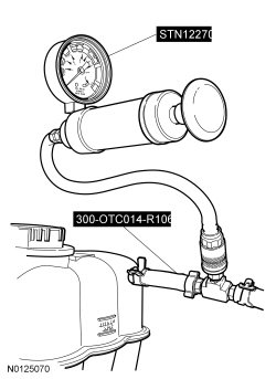
NOTICE: Do not pressurize the cooling system beyond the maximum pressure listed in the specifications table in this section or cooling system components may be damaged.
NOTE: If the plunger of the pressure tester is pressed too fast, an erroneous pressure reading results.
Slowly press the plunger of the pressure test pump until the pressure gauge reading stops increasing and note the highest pressure reading obtained. If the pressure reading exceeds the maximum cap pressure listed in the specifications table, install a new pressure relief cap.Thermostat
Install a new thermostat only after at least one of the following tests and checks have been carried out:
Thermostat Visual Inspection
NOTICE: If no damage is found during the inspection, do not attempt to open the thermostat using hot water or other heat sources. This method is not an accurate way of testing the function of the thermostat and may damage the thermostat.
If damage is found during the inspection, remove any foreign material or broken pieces and install a new thermostat.Radiator Leak Test, Removed From Vehicle
NOTICE: Never leak test an aluminum radiator in the same water that copper/brass radiators are tested in. Flux and caustic cleaners may be present in the tank and they will damage aluminum radiators.
NOTE: Clean the radiator before leak testing to avoid contamination of tank.
Leak test the radiator in clean water with air pressurized to the maximum pressure listed in the Specifications table.