SECTION 307-01: Automatic Transaxle/Transmission — 6R80
| 2014 Mustang Workshop Manual
|
INSTALLATION
| Procedure revision date: 02/06/2013
|
Transmission
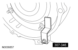
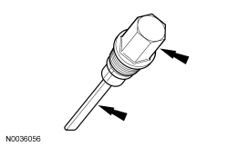
Special Tool(s)
 | Retainer, Torque Converter
307-346 (T97T-7902-A)
|
 |
Vehicle Communication Module (VCM) and Integrated Diagnostic System (IDS) software with appropriate hardware, or equivalent scan tool
|
Material
| Item
| Specification
|
|---|
Motorcraft® MERCON® LV Automatic Transmission Fluid
XT-10-QLVC (US); CXT-10-LV12 (Canada)
| MERCON® LV
|
Motorcraft® Multi-Purpose Grease
XL-5
| ESB-M1C93-B
|
Motorcraft® Threadlock and Sealer
TA-25
| WSK-M2G351-A5
|
All vehicles
NOTE:
Prior to installing a new transmission or an overhauled transmission with a new main control, record the solenoid strategy identification tag. If a new main control was installed, install the replacement solenoid body tag over the original identification tag. For additional information, refer to
Solenoid Body Strategy
in this section.
NOTICE:
Prior to installation of the transmission, lubricate the torque converter pilot hub with multi-purpose grease or damage to the torque converter or engine crankshaft can occur.
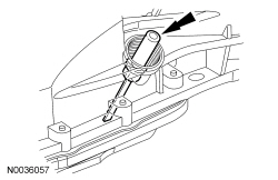
Lubricate the torque converter pilot hub with multi-purpose grease.
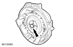
- If equipped, align the torque converter stud and flexplate hole near the paint marks at the 12 o'clock position.
- Install the Torque Converter Retainer.
 WARNING: Always secure transmission, transfer case, and axle assemblies to their service jack. Avoid obstructions while lowering and raising the jack. Improperly secured assemblies or contact with obstructions may cause the assembly to fall off the jack, which could result in serious personal injury.
NOTICE:
The torque converter housing is piloted into position by dowels in the rear of the engine block. The torque converter must rest squarely against the flexplate. This indicates that the torque converter pilot is not binding in the engine crankshaft.
NOTE:
Make sure that the transmission jack makes contact on the outer ribs of the fluid pan.
Position and secure the transmission on the high-lift transmission jack.
NOTE:
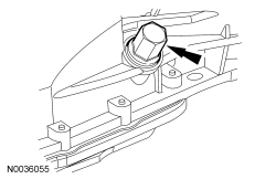
If transmission was disassembled, follow the add transmission fluid to the transmission steps. If transmission is being replaced, remove the transmission fluid fill plug and verify transmission is filled with transmission fluid.
Add transmission fluid to the transmission.
- Slightly tilt the transmission rearward.
- Remove the transmission fluid fill plug transmission fluid level indicator assembly.
- Add 11.35L (12 qt) of transmission fluid to the transmission through the transmission fluid fill hole.
- Install the transmission fluid fill plug.
- Tighten to 26 Nm (19 lb-ft).
Vehicles equipped with a 5.0L (4V) engine
NOTE:
Using the transmission jack, rotate the transmission approximately 25 degrees clockwise.
Raise and position the transmission into the vehicle behind the engine.
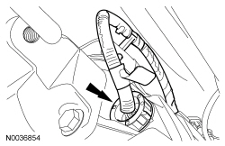
- Position the transmission vehicle wiring harness and attach the wiring harness to the top of the transmission.
- Remove the Torque Converter Retainer.
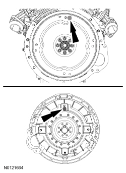
- Align the index mark on the torque converter with the index mark on the flexplate.
NOTE:
Make sure the torque converter is fully seated in the transmission before aligning the transmission to the engine.
With the transmission in a horizontal position, move it toward the engine and position it on the dowel pins.
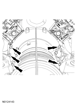
- Install the 5 transmission-to-engine bolts.
- Tighten to 48 Nm (35 lb-ft).
- Attach the wiring harness pin-type retainer to the transmission case.
Vehicles equipped with a 3.7L engine
- Raise and position the transmission into the vehicle behind the engine.
- Position the transmission vehicle wiring harness and attach the wiring harness to the top of the transmission.
- Remove the Torque Converter Retainer.
- Align the index mark on the torque converter with the index mark on the flexplate.
NOTE:
Make sure the torque converter is fully seated in the transmission before aligning the transmission to the engine.
With the transmission in a horizontal position, move it toward the engine and position it on the dowel pins.
- Install the 6 transmission-to-engine bolts.
- Tighten to 48 Nm (35 lb-ft).
All vehicles
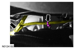
- Connect the transmission vehicle harness connector by pushing it in and twisting the outer shell to lock it in place.
- Attach the selector lever cable to the transmission case.
- Install the crossmember and the transmission insulator and the 3 transmission insulator retaining bolts.
- Tighten to 103 Nm (76 lb-ft).
- Install the 4 transmission crossmember retaining bolts.
- Tighten to 103 Nm (76 lb-ft).
Vehicles equipped with a 3.7L engine
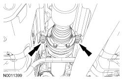
- Install 4 new flexplate-to-torque converter nuts.
- Tighten to 40 Nm (30 lb-ft).
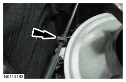
- Install the access cover and the 2 pin-type retainers.
- Raise the underbody shield and install the 3 bolts.
- Tighten to 10 Nm (89 lb-in).
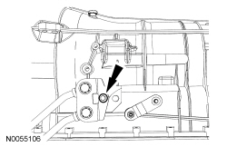
NOTE:
To make sure of correct starter installation, the upper bolt must be tightened first.
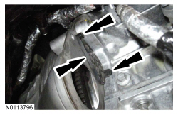
Position the starter motor and install the 2 stud bolts finger-tight.
- Tighten the upper stud bolt to 48 Nm (35 lb-ft).
- Tighten the lower stud bolt to 48 Nm (35 lb-ft).
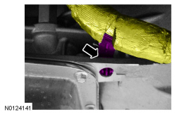
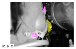
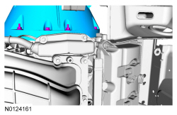
- Position the automatic transmission cooler tube bracket and install the nut.
- Tighten to 12 Nm (106 lb-in).
All vehicles
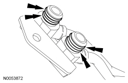
NOTE:
Inspect the case to make sure that the old transmission fluid cooler tube O-rings are not stuck in the case.
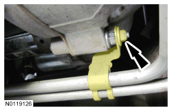
Install new transmission fluid cooler tube O-rings on the transmission fluid cooler tubes.
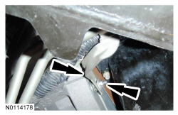
- Position the transmission fluid cooler tubes and a new transmission fluid cooler tube bracket bolt.
- Tighten to 25 Nm (18 lb-ft).
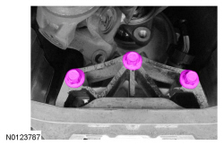
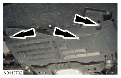
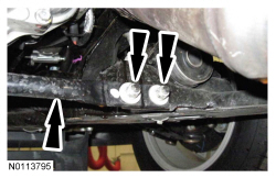
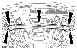
NOTE:
RH shown, LH similar.
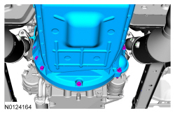
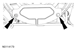
Install the front crossmember brace and the 4 nuts (2 shown).
- Tighten to 48 Nm (35 lb-ft).
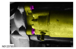
Vehicles equipped with a 5.0L (4V) engine
NOTE:
Two of the bolts are shown, the third bolt is on top of starter.
NOTE:
To make sure of correct starter installation, the upper bolt must be tightened first.
Position the starter motor and install the 3 bolts finger-tight.
- Tighten the upper bolt to 25 Nm (18 lb-ft).
- Tighten the lower 2 bolts to 25 Nm (18 lb-ft).
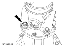
- Install 4 new flexplate-to-torque converter nuts.
- Tighten to 40 Nm (30 lb-ft).
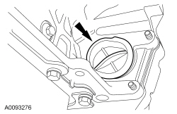
- Install the rubber torque converter nut access plug.
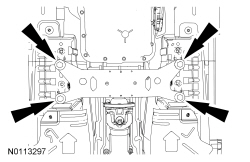
- Position the lower splash shield and install the 9 bolts.
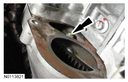
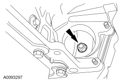
- Install the flexplate inspection cover, the bolt and stud bolt.
- Tighten to 35 Nm (26 lb-ft).
- Install the transmission fluid cooler bracket and nut to the flexplate inspection cover stud bolt.
- Tighten to 12 Nm (106 lb-in).
All vehicles
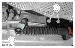
- Install the selector lever cable bracket.
- Install the selector lever cable end onto the transmission manual control lever.
- Install the selector lever cable bracket and 2 bolts onto the transmission.
- Tighten to 25 Nm (18 lb-ft).
Vehicles equipped with a 5.0L (4V) engine
NOTE:
If new driveshaft bolts or center bearing bolts are not available, coat the threads of the original bolts with threadlock and sealer and reuse the original washers and spacers.
NOTE:
The driveshaft flanges fit tightly on the transmission output flange pilot. To make sure that the driveshaft flange seats squarely on the transmission output flange, tighten the driveshaft flange bolts evenly in a cross pattern.
NOTE:
The center bearing spacers must be installed between the body and the center bearing bracket.
Position the driveshaft and install the 2 center bearing spacers and bolts.
- Install the new center bearing bolts finger-tight until after the front flange bolts are tightened to specifications.
- Tighten to 48 Nm (35 lb-ft).
- Align the index-mark and install the 4 driveshaft flange bolts.
- Tighten the new bolts evenly in a cross pattern.
- Tighten to 103 Nm (76 lb-ft).
- Install the top 2 transmission-to-engine bolts.
- Tighten to 48 Nm (35 lb-ft).
- Attach the wiring harness to the transmission stud.
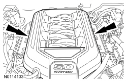
- Install the engine appearance cover.
- Connect the battery ground cable. For additional information, refer to
Section 414-01
.
Vehicles equipped with a 3.7L engine
NOTE:
If new driveshaft flange bolts are not available, coat the threads of the original bolts with threadlock and sealer.
NOTE:
The driveshaft flanges fit tightly on the pinion flange pilots. To make sure that the driveshaft flanges seat squarely on the pinion flange pilots, tighten the driveshaft flange bolts evenly in a cross pattern.
Align the index-mark and install the 4 driveshaft flange bolts.
- Tighten the new bolts evenly in a cross pattern.
- Tighten to 103 Nm (76 lb-ft).
- Install the top 2 and side 2 transmission-to-engine bolts.
- Tighten to 48 Nm (35 lb-ft).
- Attach the wiring harness to the 2 transmission studs.
- If equipped, install the engine appearance cover.
- Install the battery tray. For additional information, refer to
Section 414-01
.
All vehicles
- If equipped, install the strut tower cross brace and the 4 nuts.
- Tighten to 35 Nm (26 lb-ft).
- Verify the selector lever cable is correctly adjusted. For additional information, refer to
Section 307-05
.
- After completing the repairs, use the scan tool to perform the Misfire Monitor Neutral Profile Correction procedure, following the on-screen instructions.
- If a new transmission or a new main control was installed, the solenoid body strategy must be updated. For additional information, refer to
Solenoid Body Strategy
in this section.
- If the transmission was overhauled, the adaptive drive cycle must be updated. For additional information, refer to
Shift Point Road Test
in this section.
- While driving the vehicle, use the scan tool to verify that the Transmission Fluid Temperature (TFT) has reached a temperature of 88°C (190°F). This will circulate the transmission fluid through the torque converter and the transmission fluid cooling system, eliminating any trapped air in the transmission fluid cooling system.
- With the engine idling (600-750 rpm) in PARK, verify that the
is between 80ºC-85ºC (176ºF-185ºF).
- Remove the transmission fluid fill plug transmission fluid level indicator assembly located on the passenger side front portion of the transmission case.
- Separate the transmission fluid level indicator from the transmission fluid fill plug.
- Wipe the transmission fluid level indicator clean. Reinstall the transmission fluid level indicator only back into the transmission fluid fill plug hole to check the transmission fluid level. Repeat this until a consistent reading is established.
NOTE:
If the transmission fluid is not at the correct level, follow the steps for Adding Additional Transmission Fluid or Removing Transmission Fluid. For additional information, refer to
Transmission Fluid Drain and Refill
in this section.
Install the transmission fluid fill plug.
- Tighten to 35 Nm (26 lb-ft).