
105-R025D or equivalent

FLU77-4 or equivalent

SECTION 211-05: Steering Column Switches
| 2014 Mustang Workshop Manual
|
DIAGNOSIS AND TESTING
| Procedure revision date: 01/07/2013
|
| Flex Probe Kit
105-R025D or equivalent |
| Fluke 77-IV Digital Multimeter
FLU77-4 or equivalent |
|
Vehicle Communication Module (VCM) and Integrated Diagnostic System (IDS) software with appropriate hardware, or equivalent scan tool
|
Principles of Operation
Ignition Switch
NOTE: The Smart Junction Box (SJB) is also identified as the Generic Electronic Module (GEM).
The ignition switch has 4 possible positions:
The ignition switch is controlled by the ignition lock cylinder with a key. When the ignition lock cylinder is turned using the key, a mechanical connection positions the ignition switch to the selected position and allows the ignition switch to send voltage to the SJB and Battery Junction Box (BJB). The ignition switch contains a key-in-ignition switch and a key removal inhibit solenoid.
The key-in-ignition switch is hardwired to the Instrument Panel Cluster (IPC). The switch allows the IPC to detect when the key has been inserted in the ignition switch. The IPC uses this information for the brake shift interlock system and the chime warning system. For information on the brake shift interlock system, refer to Section 307-05 . For information on the chime warning system, refer to Section 413-01 .
The key removal inhibit solenoid (also known as the key release interlock actuator) is an electronically controlled solenoid that prevents the ignition lock cylinder from being turned to the OFF position unless the selector lever is in the PARK position. The key removal inhibit solenoid is part of the ignition switch.
Multifunction Switch
The multifunction switches control various components electrically. The headlamp switch sends constant voltage to the headlamps when placed in the ON position, while the flash-to-pass is a momentary switch used to send voltage to the headlamp high beams only. The headlamp high beam/low beam switch sends voltage to the low or high beam headlamps while the headlamps are on. The turn signal switch portion of the multifunction switch operates the left and right turn signals. The windshield wiper switch function uses a ground signal to activate the various wiper modes and the wiper/washer.
For diagnosis and testing of the multifunction switch, refer to Section 417-01 for headlamps and turn signal concerns, and Section 501-16 for wiper and washer concerns.
Inspection and Verification
Visual Inspection Chart
| Mechanical | Electrical |
|---|---|
|
|
NOTE: For multifunction switch concerns, refer to one of the following sections:
NOTE: Make sure to use the latest scan tool software release.
If the cause is not visually evident, connect the scan tool to the Data Link Connector (DLC).NOTE: The Vehicle Communication Module (VCM) LED prove out confirms power and ground from the DLC are provided to the VCM .
If the scan tool does not communicate with the VCM :Smart Junction Box (SJB) DTC Chart
| DTC | Description | Action |
|---|---|---|
| B2844 | Ignition Fault | GO to Pinpoint Test F . |
| B2A20 | Ignition Stuck in START | GO to Pinpoint Test E . |
| U2472 | Unexpected Ignition State | GO to Pinpoint Test F . |
| — | All other SJB DTCs | REFER to the Diagnostic Trouble Code (DTC) Chart in Section 419-10 . |
Symptom Chart
| Condition | Possible Sources | Action |
|---|---|---|
|
| |
|
| |
|
| |
|
| |
|
|
|
|
| |
|
| |
|
|
|
Pinpoint Tests
Pinpoint Test A: No Power in All Ignition Switch Positions
Refer to Wiring Diagrams Cell 13 , Power Distribution/SJB for schematic and connector information.
The ignition switch receives fused battery voltage from Smart Junction Box (SJB) fuse 27 (20A) along circuit SPB27 (BU/RD), this voltage is then sent to the SJB and the Battery Junction Box (BJB) for various systems depending on the ignition switch position. The ignition switch has 4 possible positions:
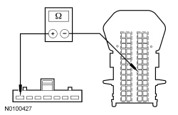
NOTICE: Use the Flex Probe Kit for all test connections to prevent damage to the wiring terminals. Do not use standard multimeter probes.
| Test Step | Result / Action to Take |
|---|---|
| A1 CHECK THE VOLTAGE AT THE IGNITION SWITCH | |
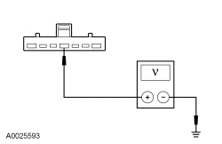 | Yes
GO to A3 . No VERIFY Smart Junction Box (SJB) fuse 27 (20A) is OK. If not OK, REFER to the Wiring Diagrams manual to identify the possible causes of the circuit short. If OK, GO to A2 . |
| A2 CHECK THE IGNITION SWITCH INPUT CIRCUIT FOR AN OPEN | |
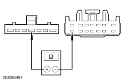 | Yes
GO to A3 . No REPAIR circuit SBP27 (BU/RD). TEST the system for normal operation. |
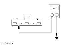
| A3 CHECK THE IGNITION SWITCH | |
| Yes
GO to A4 . No INSTALL a new ignition switch. REFER to Ignition Switch in this section. TEST the system for normal operation. |
| A4 CHECK FOR CORRECT SJB OPERATION | |
| Yes
INSTALL a new SJB . REFER to Section 419-10 . REPEAT the self-test. No The system is operating correctly at this time. The concern may have been caused by a loose or corroded connector. TEST the system for normal operation. |
Pinpoint Test B: No Power in ACC
Refer to Wiring Diagrams Cell 13 , Power Distribution/SJB for schematic and connector information.
When the ignition switch is turned to the ACC position, fused battery voltage is sent to the Smart Junction Box (SJB) run/accessory bus along circuit CDC33 (VT/GN).
NOTICE: Use the Flex Probe Kit for all test connections to prevent damage to the wiring terminals. Do not use standard multimeter probes.
NOTE: Verify that battery voltage is 10 volts or greater.
| Test Step | Result / Action to Take |
|---|---|
| B1 CHECK THE IGNITION SWITCH | |
| Yes
GO to B2 . No INSTALL a new ignition switch. REFER to Ignition Switch in this section. TEST the system for normal operation. |
| B2 CHECK THE SJB RUN/ACC CIRCUIT FOR AN OPEN | |
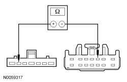 | Yes
GO to B3 . No REPAIR circuit CDC33 (VT/GN). TEST the system for normal operation. |
| B3 CHECK THE SJB RUN/ACC CIRCUIT FOR A SHORT TO GROUND | |
 | Yes
GO to B4 . No REPAIR circuit CDC33 (VT/GN). TEST the system for normal operation. |
| B4 CHECK FOR CORRECT SJB OPERATION | |
| Yes
INSTALL a new SJB . REFER to Section 419-10 . REPEAT the self-test. No The system is operating correctly at this time. The concern may have been caused by a loose or corroded connector. TEST the system for normal operation. |
Pinpoint Test C: No Power in RUN
Refer to Wiring Diagrams Cell 13 , Power Distribution/SJB for schematic and connector information.
When the ignition switch is placed in the RUN position, fused ignition voltage is sent to the Smart Junction Box (SJB) and the Battery Junction Box (BJB) along circuit CE612 (GY/VT).
NOTICE: Use the Flex Probe Kit for all test connections to prevent damage to the wiring terminals. Do not use standard multimeter probes.
NOTE: Verify that battery voltage is greater than 10 volts.
| Test Step | Result / Action to Take |
|---|---|
| C1 CHECK THE IGNITION SWITCH | |
| Yes
GO to C2 . No INSTALL a new ignition switch. REFER to Ignition Switch in this section. TEST the system for normal operation. |
| C2 CHECK THE RUN CIRCUIT FOR AN OPEN | |
   | Yes
GO to C3 . No REPAIR circuit CE612 (GY/VT). TEST the system for normal operation. |
| C3 CHECK THE RUN CIRCUIT FOR A SHORT TO GROUND | |
 | Yes
GO to C4 . No REPAIR circuit CE612 (GY/VT). TEST the system for normal operation. |
| C4 CHECK FOR CORRECT SJB OPERATION | |
| Yes
INSTALL a new SJB . REFER to Section 419-10 . REPEAT the self-test. No The system is operating correctly at this time. The concern may have been caused by a loose or corroded connector. TEST the system for normal operation. |
Pinpoint Test D: No Power in START
Refer to Wiring Diagrams Cell 13 , Power Distribution/SJB for schematic and connector information.
When the ignition switch is placed in the START position, fused ignition voltage is sent to the Smart Junction Box (SJB) start bus along circuit CDC35 (BU/WH).
NOTICE: Use the Flex Probe Kit for all test connections to prevent damage to the wiring terminals. Do not use standard multimeter probes.
NOTE: Verify that battery voltage is greater than 10 volts.
| Test Step | Result / Action to Take |
|---|---|
| D1 CHECK THE IGNITION SWITCH | |
| Yes
GO to D2 . No INSTALL a new ignition switch. REFER to Ignition Switch in this section. TEST the system for normal operation. |
| D2 CHECK THE START CIRCUIT FOR AN OPEN | |
 | Yes
GO to D3 . No REPAIR circuit CDC35 (BU/WH). TEST the system for normal operation. |
| D3 CHECK THE START CIRCUIT FOR A SHORT TO GROUND | |
 | Yes
REFER to Section 303-06 to diagnose the starting system. No REPAIR circuit CDC35 (BU/WH). TEST the system for normal operation. |
Pinpoint Test E: DTC B2A20
Refer to Wiring Diagrams Cell 13 , Power Distribution/SJB for schematic and connector information.
The ignition switch is spring loaded to automatically return to the RUN position after being placed in the START position. A microprocessor in the Smart Junction Box (SJB) monitors the voltage output from the ignition switch while the switch is in the START position.
NOTICE: Use the Flex Probe Kit for all test connections to prevent damage to the wiring terminals. Do not use standard multimeter probes.
| Test Step | Result / Action to Take |
|---|---|
| E1 CHECK THE IGNITION SWITCH | |
| Yes
GO to E2 . No INSTALL a new ignition switch. REFER to Ignition Switch in this section. CLEAR the DTC. TEST the system for normal operation. |
| E2 CHECK THE ELECTRICAL FUNCTION OF THE IGNITION SWITCH | |
| Yes
GO to E3 . No INSTALL a new ignition switch. REFER to Ignition Switch in this section. CLEAR the DTC. TEST the system for normal operation. |
| E3 CHECK THE SJB PID | |
| Yes
GO to E11 . No GO to E4 . |
| E4 ISOLATE THE ACM | |
| Yes
GO to E9 . No GO to E5 . |
| E5 CHECK THE START CIRCUIT TO THE ACM FOR A SHORT TO VOLTAGE | |
 | Yes
REPAIR the circuit. CLEAR the DTCs. REPEAT the self-test. No GO to E6 |
| E6 ISOLATE THE START RELAY CONTROL CIRCUIT | |
| Yes
INSTALL a new relay. TEST the system for normal operation. No GO to E7 . |
| E7 CHECK THE IGNITION START CIRCUIT FOR A SHORT TO VOLTAGE | |
| Yes
GO to E10 . No GO to E8 . |
| E8 CHECK THE START CIRCUIT TO THE PCM FOR A SHORT TO VOLTAGE | |
| Yes
REPAIR the circuit. CLEAR the DTCs. REPEAT the self-test. No GO to E11 . |
| E9 CHECK THE AUDIO CONTROL MODULE (ACM) FOR CORRECT OPERATION | |
| Yes
INSTALL a new ACM . REFER to Section 415-00 . REPEAT the self-test, then TEST the system for normal operation. No The system is operating correctly at this time. The concern may have been caused by a loose or corroded connector. |
| E10 CHECK THE PCM FOR CORRECT OPERATION | |
| Yes
INSTALL a new PCM . REFER to Section 303-14 . CLEAR the DTCs. REPEAT the self-test, then TEST the system for normal operation. No The system is operating correctly at this time. The concern may have been caused by a loose or corroded connector. |
| E11 CHECK THE SJB FOR CORRECT OPERATION | |
| Yes
INSTALL a new SJB . REFER to Section 419-10 . REPEAT the self-test, then TEST the system for normal operation. No The system is operating correctly at this time. The concern may have been caused by a loose or corroded connector. |
Pinpoint Test F: DTCs B2844 and U2472
Refer to Wiring Diagrams Cell 13 , Power Distribution/SJB for schematic and connector information.
Microprocessors in the Smart Junction Box (SJB) continuously monitor the ignition switch state.
If DTC U2472 was set immediately following an SJB on-demand self test. Clear the SJB DTCs and repeat the self-test making sure that the ignition is in RUN. If DTC U2472 returns again, continue with Pinpoint Test F.
NOTICE: Use the Flex Probe Kit for all test connections to prevent damage to the wiring terminals. Do not use standard multimeter probes.
| Test Step | Result / Action to Take |
|---|---|
| F1 REVIEW THE SJB DTCs | |
| Yes
GO to Pinpoint Test E . No For DTCs B2844 and U2472, GO to F2 . For all other SJB DTCs, REFER to Section 419-10 . |
| F2 CHECK THE IGNITION SWITCH | |
| Yes
GO to F3 . No INSTALL a new ignition switch. REFER to Ignition Switch in this section. CLEAR the DTC. REPEAT the self-test. |
| F3 CHECK THE IGNITION SWITCH PIDs | |
| Yes
The system is operating correctly at this time. The concern may have been caused by a loose or corroded connector. CLEAR the DTC(s). REPEAT the self-test and TEST the system for normal operation. No If IGN_R_ECU displays No, GO to F4 . If IGN_A_ECU displays Yes, GO to F5 . If IGN_S_ECU displays Yes, GO to Pinpoint Test E . |
| F4 CHECK THE IGNITION RUN CIRCUIT FOR AN OPEN | |
 | Yes
GO to F6 . No REPAIR circuit CE612 (GY/VT). CLEAR the DTC. REPEAT the self-test. |
| F5 CHECK THE IGNITION ACCESSORY CIRCUITS FOR A SHORT TO VOLTAGE | |
| Yes
REFER to the Wiring Diagrams manual to identify the cause of the circuit short. No REPAIR circuit CDC33 (VT/GN). CLEAR the DTC. TEST the system for normal operation. |
| F6 CHECK THE SJB CONNECTORS | |
| Yes
INSTALL a new SJB . REFER to Section 419-10 . REPEAT the self-test, then TEST the system for normal operation. No The system is operating correctly at this time. The concern may have been caused by a loose or corroded connector. |
Pinpoint Test G: The Ignition Key Cannot Be Returned to the OFF Position
Refer to Wiring Diagrams Cell 37 , Shift Interlock for schematic and connector information.
The key removal inhibit solenoid (part of the ignition switch) receives battery voltage from Smart Junction Box (SJB) fuse 27 (20A) through circuit SBP27 (BU/RD). When the selector lever is moved out of the PARK position, the park range switch (part of the selector lever) closes and connects circuit CDC41 (WH/BN) to circuit GD139 (BK/YE), providing ground to the key removal inhibit solenoid. The key removal inhibit solenoid activates and prevents the ignition lock cylinder from being turned to the OFF position and the key removed.
NOTICE: Use the Flex Probe Kit for all test connections to prevent damage to the wiring terminals. Do not use standard multi-meter probes.
| Test Step | Result / Action to Take |
|---|---|
| G1 CHECK FOR AN ENERGIZED KEY REMOVAL INHIBIT SOLENOID | |
| Yes
GO to G4 . No GO to G2 . |
| G2 CHECK THE IGNITION SWITCH FOR MECHANICAL DAMAGE | |
| Yes
INSTALL a new ignition switch. REFER to Ignition Switch in this section. TEST the system for normal operation. No GO to G3 . |
| G3 CHECK THE IGNITION LOCK CYLINDER FOR MECHANICAL DAMAGE | |
| Yes
INSTALL a new steering column lock module. REFER to Steering Column Lock Module in this section. TEST the system for normal operation. No INSTALL a new ignition lock cylinder. REFER to Section 501-14 . TEST the system for normal operation. |
| G4 CHECK THE KEY REMOVAL INHIBIT SOLENOID CIRCUIT FOR A SHORT TO GROUND | |
 | Yes
INSTALL a new ignition switch. REFER to Ignition Switch in this section. TEST the system for normal operation. No For vehicles equipped with a manual transmission, REPAIR circuit CDC41 (WH/BN). TEST the system for normal operation. For vehicles equipped with an automatic transmission, GO to G5 . |
| G5 ISOLATE THE SHORT TO GROUND IN THE KEY REMOVAL INHIBIT SOLENOID CIRCUIT | |
| Yes
INSTALL a new selector lever. REFER to Section 307-05 . TEST the system for normal operation. No REPAIR circuit CDC41 (WH/BN). TEST the system for normal operation. |
Pinpoint Test H: The Ignition Key Can be Turned to the OFF Position When the Selector Lever is not in PARK
Refer to Wiring Diagrams Cell 37 , Shift Interlock for schematic and connector information.
The key removal inhibit solenoid (part of the ignition switch) receives battery voltage from Smart Junction Box (SJB) fuse 27 (20A) through circuit SBP27 (BU/RD). When the selector lever is moved out of the PARK position, the park range switch (part of the selector lever) closes and connects circuit CDC41 (WH/BN) to circuit GD139 (BK/YE), providing ground to the key removal inhibit solenoid. The key removal inhibit solenoid activates and prevents the ignition lock cylinder from being turned to the OFF position and the key removed.
NOTICE: Use the Flex Probe Kit for all test connections to prevent damage to the wiring terminals. Do not use standard multi-meter probes.
| Test Step | Result / Action to Take |
|---|---|
| H1 CHECK THE KEY REMOVAL INHIBIT SOLENOID CIRCUIT FOR GROUND | |
 | Yes
INSTALL a new ignition switch. REFER to Ignition Switch in this section. TEST the system for normal operation. No GO to H2 . |
| H2 CHECK THE KEY REMOVAL INHIBIT SOLENOID CIRCUIT FOR AN OPEN | |
 | Yes
GO to H3 . No REPAIR circuit CDC41 (WH/BN). TEST the system for normal operation. |
| H3 CHECK THE FLOOR SHIFTER GROUND CIRCUIT FOR AN OPEN | |
 | Yes
INSTALL a new selector lever. REFER to Section 307-05 . TEST the system for normal operation. No REPAIR circuit GD139 (BK/YE). TEST the system for normal operation. |
Component Tests
Ignition Switch — Mechanical
The following conditions can cause difficulty in operating the ignition switch and lock cylinder:
If the steering wheel lock is engaged with the wheels loaded against a curb, high effort will be necessary to turn the key from lock. Turn the steering wheel to either side of the lock to unload the system.
Carry out the following test to determine if the ignition switch and lock cylinder are operating correctly.
NOTE: The steering wheel may be locked full left or full right. If the steering wheel is locked, it will be necessary to apply turning effort to the steering wheel in the direction of the lock while turning the key.
Turn the key to the ACC position and then the RUN position.NOTE: The ignition switch and lock cylinder should return from the START position back to the RUN position without assistance.
Turn the ignition key to the START position and release the key.