
219-00074 or equivalent

NUD105-R025D or equivalent

014-R1072 or equivalent

176-R032A or equivalent
216-00001 or equivalent

SGT27000 or equivalent 250-300 mA incandescent bulb test lamp
SECTION 412-00: Climate Control System — General Information and Diagnostics
| 2014 Mustang Workshop Manual
|
DIAGNOSIS AND TESTING
| Procedure revision date: 06/07/2013
|
| A/C Flush Adapter Kit
219-00074 or equivalent |
| Flex Probe Kit
NUD105-R025D or equivalent |
| Pressure Test Kit
014-R1072 or equivalent |
| R-134a Manifold Gauge Set
176-R032A or equivalent |
| Refrigerant Leak Detector
216-00001 or equivalent |
| Test Light
SGT27000 or equivalent 250-300 mA incandescent bulb test lamp |
Principles of Operation
The Refrigerant Cycle
During stabilized conditions (A/C system shutdown), the refrigerant pressures are equal throughout the system. When the A/C compressor is in operation, it increases pressure on the refrigerant vapor, raising its temperature. The high-pressure and high-temperature vapor is then released into the top of the A/C condenser core.
The A/C condenser, being close to ambient temperature, causes the refrigerant vapor to condense into a liquid when heat is removed from the refrigerant by ambient air passing over the fins and tubing. The now liquid refrigerant, still at high pressure, exits from the bottom of the A/C condenser and enters the inlet side of the A/C receiver/drier. The receiver/drier is designed to remove moisture from the refrigerant.
The outlet of the receiver/drier is connected to the Thermostatic Expansion Valve (TXV). The TXV provides the orifice which is the restriction in the refrigerant system and separates the high and low pressure sides of the A/C system. As the liquid refrigerant passes across this restriction, its pressure and boiling point are reduced.
The liquid refrigerant is now at its lowest pressure and temperature. As it passes through the A/C evaporator, it absorbs heat from the airflow passing over the plate/fin sections of the A/C evaporator. This addition of heat causes the refrigerant to boil (convert to gas). The now cooler air can no longer support the same humidity level of the warmer air and this excess moisture condenses on the exterior of the evaporator coils and fins and drains outside the vehicle.
The refrigerant cycle is now repeated with the A/C compressor again increasing the pressure and temperature of the refrigerant.
A thermistor which monitors the temperature of the air that has passed through the evaporator core controls A/C clutch cycling. If the temperature of the evaporator core discharge air is low enough to cause the condensed water vapor to freeze, the A/C clutch is disengaged by the vehicle PCM.
The high-side line pressure is also monitored so that A/C compressor operation will be interrupted if the system pressure becomes too high or is determined to be too low (low charge condition).
The A/C compressor relief valve will open and vent refrigerant to relieve unusually high system pressure.

| Item | Description |
|---|---|
| 1 | A/C evaporator core |
| 2 | A/C evaporator core outlet temperature thermistor |
| 3 | Thermostatic Expansion Valve (TXV) |
| 4 | Manifold and tube assembly — TXV |
| 5 | A/C charge valve port (low side) |
| 6 | Manifold and tube assembly — A/C compressor |
| 7 | A/C compressor |
| 8 | A/C pressure relief valve |
| 9 | A/C pressure transducer |
| 10 | Low-pressure vapor |
| 11 | High-pressure vapor |
| 12 | Low-pressure liquid |
| 13 | High-pressure liquid |
| 14 | A/C condenser core |
| 15 | A/C receiver/drier |
| 16 | Manifold and tube assembly — receiver/drier |
| 17 | A/C charge valve port (high side) |
Inspection and Verification
Visual Inspection Chart
| Mechanical | Electrical |
|---|---|
|
|
NOTE: Make sure to use the latest scan tool software release.
If the cause is not visually evident, connect the scan tool to the Data Link Connector (DLC).NOTE: The Vehicle Communication Module (VCM) LED prove-out confirms power and ground from the DLC are provided to the VCM .
If the scan tool does not communicate with the VCM :NOTE: Some PCM DTCs may inhibit A/C operation. If any PCM DTCs are retrieved, diagnose those first. Refer to the PCM DTC Chart.
If the HVAC DTCs retrieved are related to the concern, go to the HVAC Module DTC Chart. If the PCM DTCs retrieved are related to the concern, go to the PCM DTC Chart. For all other DTCs, refer to Section 419-10 .DTC Charts
NOTE: Network DTCs (U-codes) are often a result of intermittent concerns such as damaged wiring or low battery voltage occurrences. Additionally, vehicle repair procedures such as module reprogramming often set network DTCs. Replacing a module to resolve a network DTC is unlikely to resolve the concern. To prevent repeat network DTC concerns, inspect all network wiring, especially connectors. Test the vehicle battery, refer to Section 414-01 .
PCM DTC Chart
| DTC | Description | Action to Take |
|---|---|---|
| P0532 | A/C Refrigerant Pressure Sensor A Circuit Low | GO to Pinpoint Test a . |
| P0533 | A/C Refrigerant Pressure Sensor A Circuit High | GO to Pinpoint Test a . |
| P0645 | Air Conditioning Clutch Relay (A/CCR) Control Circuit | GO to Pinpoint Test b . |
| P1464 | A/C Demand Out Of Self Test Range | If the HVAC selector was not in the OFF position, place it in the OFF position, CLEAR the DTCs and REPEAT the self-test. If the DTC does not return, ignore the DTC and continue diagnostics. If the DTC returns, INSTALL a new HVAC module. CLEAR the DTCs and REPEAT the self-test. |
| All Other DTCs | — | REFER to Powertrain Control/Emissions Diagnosis (PC/ED) manual. |
HVAC Module DTC Chart
NOTE: This module utilizes a 5-character DTC followed by a 2-character failure-type code. The failure-type code provides information about specific fault conditions such as opens or shorts to ground. CMDTCs have an additional 2-character DTC status code suffix to assist in determining DTC history.
NOTE: Some PCM DTCs may inhibit A/C operation. If any PCM DTCs are retrieved, diagnose those first. Refer to the PCM DTC Chart.
| DTC | Description | Action to Take |
|---|---|---|
| B1030:11 | Left Front Seat Heater: Circuit Short to Ground | REFER to Section 501-10 . |
| B1030:12 | Left Front Seat Heater: Circuit Short to Battery | REFER to Section 501-10 . |
| B1030:13 | Left Front Seat Heater: Circuit Open | REFER to Section 501-10 . |
| B1032:11 | Right Front Seat Heater: Circuit Short to Ground | REFER to Section 501-10 . |
| B1032:12 | Right Front Seat Heater: Circuit Short to Battery | REFER to Section 501-10 . |
| B1032:13 | Right Front Seat Heater: Circuit Open | REFER to Section 501-10 . |
| B1081:00 | Left Temperature Damper Motor: No Sub Type Information | GO to Pinpoint Test P . |
| B1081:11 | Left Temperature Damper Motor: Circuit Short to Ground | GO to Pinpoint Test P . |
| B1081:12 | Left Temperature Damper Motor: Circuit Short to Battery | GO to Pinpoint Test P . |
| B1082:00 | Right Temperature Damper Motor: No Sub Type Information | GO to Pinpoint Test P . |
| B1082:11 | Right Temperature Damper Motor: Circuit Short to Ground | GO to Pinpoint Test P . |
| B1082:12 | Right Temperature Damper Motor: Circuit Short to Battery | GO to Pinpoint Test P . |
| B1083:00 | Recirculation Damper Motor: No Sub Type Information | GO to Pinpoint Test J . |
| B1083:11 | Recirculation Damper Motor: Circuit Short to Ground | GO to Pinpoint Test J . |
| B1083:12 | Recirculation Damper Motor: Circuit Short to Battery | GO to Pinpoint Test J . |
| B1086:00 | Air Distribution Damper Motor: No Sub Type Information | GO to Pinpoint Test K . |
| B1086:11 | Air Distribution Damper Motor: Circuit Short to Ground | GO to Pinpoint Test K . |
| B1086:12 | Air Distribution Damper Motor: Circuit Short to Battery | GO to Pinpoint Test K . |
| B10AF:11 | Blower Fan Relay: Circuit Short to Ground | GO to Pinpoint Test R . |
| B10AF:12 | Blower Fan Relay: Circuit Short to Battery | GO to Pinpoint Test Q . |
| B10AF:13 | Blower Fan Relay: Circuit Open | GO to Pinpoint Test Q . |
| B10B9:12 | Blower Control: Circuit Short to Battery | GO to Pinpoint Test R . |
| B10B9:14 | Blower Control: Circuit Short to Ground or Open | GO to Pinpoint Test Q . |
| B11E5:11 | Left HVAC Damper Position Sensor: Circuit Short to Ground | GO to Pinpoint Test P . |
| B11E5:15 | Left HVAC Damper Position Sensor: Circuit Short to Battery or Open | GO to Pinpoint Test P . |
| B11E6:11 | Right HVAC Damper Position Sensor: Circuit Short to Ground | GO to Pinpoint Test P . |
| B11E6:15 | Right HVAC Damper Position Sensor: Circuit Short to Battery or Open | GO to Pinpoint Test P . |
| B11E7:11 | Air Distribution Damper Position Sensor: Circuit Short to Ground | GO to Pinpoint Test K . |
| B11E7:15 | Air Distribution Damper Position Sensor: Circuit Short to Battery or Open | GO to Pinpoint Test K . |
| B125B:10 | Air Distribution Damper "B" Motor: No Sub Type Information | GO to Pinpoint Test K . |
| B125B:11 | Air Distribution Damper "B" Motor: Circuit Short to Ground | GO to Pinpoint Test K . |
| B125B:12 | Air Distribution Damper "B" Motor: Circuit Short to Battery | GO to Pinpoint Test K . |
| B1A61:11 | Cabin Temperature Sensor: Circuit Short to Ground | GO to Pinpoint Test D . |
| B1A61:15 | Cabin Temperature Sensor: Circuit Short to Battery or Open | GO to Pinpoint Test D . |
| B1A63:11 | Right Solar Sensor: Circuit Short to Ground | GO to Pinpoint Test F . |
| B1A63:15 | Right Solar Sensor: Circuit Short to Battery or Open | GO to Pinpoint Test F . |
| B1A64:11 | Left Solar Sensor: Circuit Short to Ground | GO to Pinpoint Test F . |
| B1A64:15 | Left Solar Sensor: Circuit Short to Battery or Open | GO to Pinpoint Test F . |
| B1A68:11 | Ambient Temperature Sensor: Circuit Short to Ground | GO to Pinpoint Test E . |
| B1A68:15 | Ambient Temperature Sensor: Circuit Short to Battery or Open | GO to Pinpoint Test E . |
| B1B71:11 | Evaporator Temperature Sensor: Circuit Short to Ground | GO to Pinpoint Test G . |
| B1B71:15 | Evaporator Temperature Sensor: Circuit Short to Battery or Open | GO to Pinpoint Test G . |
| B1C83:11 | Rear Defog Relay: Circuit Short to Ground | REFER to Section 501-11 . |
| B1C83:12 | Rear Defog Relay: Circuit Short to Battery | REFER to Section 501-11 . |
| B1C83:13 | Rear Defog Relay: Circuit Open | REFER to Section 501-11 . |
| C1B14:11 | Sensor Supply Voltage A: Circuit Short to Ground | GO to Pinpoint Test C . |
| C1B14:12 | Sensor Supply Voltage A: Circuit Short to Battery | GO to Pinpoint Test C . |
| U0140:87 | Lost Communication With Body Control Module: Missing Message | This DTC can set because the Smart Junction Box (SJB) is unable to communicate with the HVAC module over the Controller Area Network (CAN) bus. CARRY OUT a self-test of the SJB . If the scan tool indicates that the SJB is not responding, REFER to Section 418-00 to diagnose the network communication concern. If SJB DTCs are present, REFER to Section 419-10 . |
| U0155:87 | Lost Communication With Instrument Panel Cluster (IPC) Module: Missing Message | This DTC can set because the IPC is unable to communicate with the HVAC module over the Controller Area Network (CAN) bus. CARRY OUT a self-test of the IPC . If the scan tool indicates that the IPC is not responding, REFER to Section 418-00 to diagnose the network communication concern. If IPC DTCs are present, REFER to Section 419-10 . |
| U0163:87 | Lost Communication With Navigation Control Module: Missing Message | This DTC can set because the Audio Front Control Module (ACM) is unable to communicate with the HVAC module over the Controller Area Network (CAN) bus. CARRY OUT a self-test of the ACM . If the scan tool indicates that the ACM is not responding, REFER to Section 418-00 to diagnose the network communication concern. If ACM DTCs are present, REFER to Section 419-10 . |
| U0256:87 | Lost Communication With Front Controls Interface Module (FCIM) "A": Missing Message | This DTC can set because the FCIM is unable to communicate with the HVAC module over the Controller Area Network (CAN) bus. CARRY OUT a self-test of the FCIM . If the scan tool indicates that the FCIM is not responding, REFER to Section 418-00 to diagnose the network communication concern. If FCIM DTCs are present, REFER to Section 419-10 . |
| U0422:68 | Invalid Data Received From Body Control Module: Event Information | This DTC can set due to a fault in the Smart Junction Box (SJB). CARRY OUT a self-test of the SJB . If the scan tool indicates that the SJB is not responding, REFER to Section 418-00 to diagnose the network communication concern. If SJB DTCs are present, REFER to Section 419-10 . |
| U0423:68 | Invalid Data Received From Instrument Panel Cluster Control Module: Event Information | This DTC can set because the Instrument Panel Cluster (IPC). CARRY OUT a self-test of the IPC . If the scan tool indicates that the IPC is not responding, REFER to Section 418-00 to diagnose the network communication concern. If IPC DTCs are present, REFER to Section 419-10 . |
| U0464:68 | Invalid Data Received From Navigation Control Module: Event Information | This DTC can set due to a fault in the Audio Front Control Module (ACM). CARRY OUT a self-test of the ACM . If the scan tool indicates that the ACM is not responding, REFER to Section 418-00 to diagnose the network communication concern. If ACM DTCs are present, REFER to Section 415-00 to diagnose the ACM fault. |
| U0557:68 | Invalid Data Received From Front Controls Interface Module (FCIM) "A": Event Information | This DTC can set due to a fault in the FCIM . CARRY OUT a self-test of the FCIM . If the scan tool indicates that the FCIM is not responding, REFER to Section 418-00 to diagnose the network communication concern. If FCIM DTCs are present, REFER to Section 415-00 to diagnose the FCIM fault. |
| U3000:41 | Control Module: General Checksum Failure | INSTALL a new HVAC module. REFER to Section 412-01 . |
| U3003:16 | Battery Voltage: Circuit Voltage Below Threshold | GO to Pinpoint Test H . |
| U3003:17 | Battery Voltage: Circuit Voltage Above Threshold | GO to Pinpoint Test H . |
| All Other DTCs | — | REFER to the Master DTC Chart in Section 419-10 . |
Symptom Chart — Climate Control Systems
| Condition | Possible Sources | Action |
|---|---|---|
|
|
|
|
| |
|
| |
|
|
|
|
| |
|
| |
|
| |
|
| |
|
| |
|
| |
|
| |
|
| |
|
| |
|
|
|
|
| |
|
|
|
Symptom Chart — NVH
| Condition | Possible Sources | Action |
|---|---|---|
|
|
|
|
| |
|
|
Pinpoint Tests
Pinpoint Test A: DTC P0532 or P0533
Refer to Wiring Diagrams Cell 54 , Manual Climate Control System for schematic and connector information.
Refer to Wiring Diagrams Cell 55 , Automatic Climate Control System for schematic and connector information.
Under normal operation, the A/C pressure transducer receives a ground from the PCM. A 5-volt reference voltage is supplied to the A/C pressure transducer from the PCM. The A/C pressure transducer then sends a voltage to the PCM to indicate the A/C pressure.
| Test Step | Result / Action to Take |
|---|---|
| A1 COMPARE THE A/C PRESSURE SENSOR (ACP_PRESS) PCM PARAMETER IDENTIFICATION (PID) WITH THE MANIFOLD GAUGE SET READINGS | |
| Yes
IGNORE the Diagnostic Trouble Codes (DTCs). REFER to the Symptom Chart in this section. No GO to A2 . |
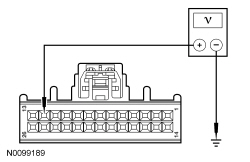
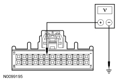
| A2 CHECK THE PCM OUTPUT VOLTAGE | |
 | Yes
GO to A3 . No If the voltage is below 4.7 volts, REPAIR circuit LE423 (GN/VT) for an open or high resistance. CLEAR the DTCs. REPEAT the self-test. TEST the system for normal operation. If the voltage is greater than 5.1 volts REPAIR circuit LE423 (GN/VT) for a short to voltage. CLEAR the DTCs. REPEAT the self-test. TEST the system for normal operation. |
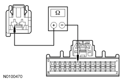
| A3 CHECK THE PCM SENSOR GROUND | |
 | Yes
If diagnosing DTC P0532 , GO to A4 . If diagnosing DTC P0533 , GO to A6 . No REPAIR circuit RE405 (GN/WH) for an open. CLEAR the DTCs. REPEAT the self-test. TEST the system for normal operation. |
| A4 CHECK THE A/C PRESSURE SENSOR (ACP_V) PCM PID WITH THE A/C PRESSURE TRANSDUCER DISCONNECTED | |
| Yes
INSTALL a new A/C pressure transducer. CLEAR the DTCs. REPEAT the self-test. TEST the system for normal operation. No GO to A5 . |
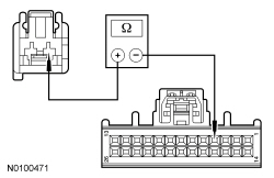
| A5 CHECK CIRCUIT VH433 (VT/OG) FOR A SHORT TO GROUND | |
 | Yes
GO to A6 . No REPAIR circuit VH433 (VT/OG) for a short to ground. CLEAR the DTCs. REPEAT the self-test. TEST the system for normal operation. |
| A6 CHECK CIRCUIT VH433 (VT/OG) FOR AN OPEN | |
 | Yes
GO to A7 . No REPAIR circuit VH433 (VT/OG) for an open. CLEAR the DTCs. REPEAT the self-test. TEST the system for normal operation. |
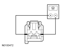
| A7 CHECK THE A/C PRESSURE SENSOR (ACP_V) PCM PID WITH THE A/C PRESSURE TRANSDUCER SHORTED | |
 | Yes
INSTALL a new A/C pressure transducer. CLEAR the DTCs. REPEAT the self-test. TEST the system for normal operation. No GO to A8 . |
| A8 CHECK CIRCUIT VH433 (VT/OG) FOR A SHORT TO VOLTAGE | |
 | Yes
REPAIR circuit VH433 (VT/OG) for a short to voltage. CLEAR the DTCs. REPEAT the self-test. TEST the system for normal operation. No GO to A9 . |
| A9 CHECK CIRCUIT VH433 (VT/OG) FOR A SHORT TO CIRCUIT RE405 (GN/WH) | |
 | Yes
GO to A10 . No REPAIR circuit VH433 (VT/OG) for a short to circuit RE405 (GN/WH). CLEAR the DTCs. REPEAT the self-test. TEST the system for normal operation. |
| A10 CHECK CIRCUIT VH433 (VT/OG) FOR A SHORT TO CIRCUIT LE423 (GN/VT) | |
 | Yes
GO to A11 . No REPAIR circuit VH433 (VT/OG) for a short to circuit LE423 (GN/VT). CLEAR the DTCs. REPEAT the self-test. TEST the system for normal operation. |
| A11 CHECK THE PCM CONNECTION | |
| Yes
INSTALL a new PCM. TEST the system for normal operation. No The system is operating correctly at this time. The concern may have been caused by a loose or corroded connector. |
Pinpoint Test B: DTC P0645
Refer to Wiring Diagrams Cell 54 , Manual Climate Control System for schematic and connector information.
Refer to Wiring Diagrams Cell 55 , Automatic Climate Control System for schematic and connector information.
Under normal operation, voltage is provided to the A/C clutch relay coil. When A/C is requested and A/C line pressures allow, a ground is provided to the A/C clutch relay coil from the PCM, energizing the A/C clutch relay.
| Test Step | Result / Action to Take |
|---|---|
| B1 CHECK THE VOLTAGE TO THE A/C CLUTCH RELAY | |
 | Yes
CARRY OUT the A/C clutch relay component test. Refer to Wiring Diagrams Cell 149 for component testing. If the relay tests OK, GO to B2 .No REPAIR circuit CBB46 (WH/BU) for an open. CLEAR the DTCs. REPEAT the self-test. TEST the system for normal operation. |
| B2 CHECK CIRCUIT CH302 (WH/BN) FOR A SHORT TO VOLTAGE | |
 | Yes
REPAIR circuit CH302 (WH/BN) for a short to voltage. CLEAR the DTCs. REPEAT the self-test. TEST the system for normal operation. No GO to B3 . |
| B3 CHECK CIRCUIT CH302 (WH/BN) FOR A SHORT TO GROUND | |
 | Yes
GO to B4 . No REPAIR circuit CH302 (WH/BN) for a short to ground. CLEAR the DTCs. REPEAT the self-test. TEST the system for normal operation. |
| B4 CHECK CIRCUIT CH302 (WH/BN) FOR AN OPEN | |
 | Yes
GO to B5 . No REPAIR circuit CH302 (WH/BN) for an open. CLEAR the DTCs. REPEAT the self-test. TEST the system for normal operation. |
| B5 CHECK THE PCM CONNECTION | |
| Yes
INSTALL a new PCM. TEST the system for normal operation. No The system is operating correctly at this time. The concern may have been caused by a loose or corroded connector. |
Pinpoint Test C: DTCs C1B14:11 and C1B14:12
Refer to Wiring Diagrams Cell 54 , Manual Climate Control System for schematic and connector information.
Refer to Wiring Diagrams Cell 55 , Automatic Climate Control System for schematic and connector information.
Under normal operation, a 5-volt reference voltage is supplied to the sensors and actuators from the HVAC module.
| Test Step | Result / Action to Take |
|---|---|
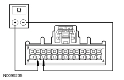
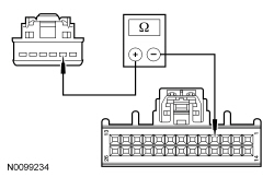
| C1 CHECK THE SENSOR RESISTANCE | |
| Yes
GO to C2 . No GO to C4 . |
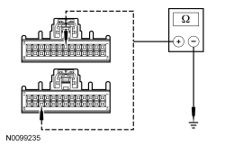
| C2 CHECK CIRCUIT LH111 (BN/WH) FOR A SHORT TO GROUND | |
 | Yes
GO to C3 . No REPAIR circuit LH111 (BN/WH) for a short to ground. CLEAR the DTCs. REPEAT the self-test. TEST the system for normal operation. |
| C3 CHECK CIRCUITS LH111 (BN/WH) AND RH111 (GY/BU) FOR A SHORT TOGETHER | |
 | Yes
GO to C5 . No REPAIR circuits LH111 (BN/WH) and RH111 (GY/BU) for a short together. CLEAR the DTCs. REPEAT the self-test. TEST the system for normal operation. |
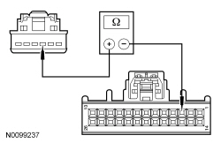
| C4 CHECK CIRCUIT LH111 (BN/WH) FOR A SHORT TO VOLTAGE | |
 | Yes
REPAIR circuit LH111 (BN/WH) for a short to voltage. CLEAR the DTCs. REPEAT the self-test. TEST the system for normal operation. No GO to C5 . |
| C5 CHECK THE HVAC MODULE CONNECTION | |
| Yes
INSTALL a new HVAC module. REFER to Section 412-01 . TEST the system for normal operation. No The system is operating correctly at this time. The concern may have been caused by a loose or corroded connector. CLEAR the DTCs. REPEAT the self-test. TEST the system for normal operation. |
Pinpoint Test D: DTCs B1A61:11 and B1A61:15
Refer to Wiring Diagrams Cell 55 , Automatic Climate Control System for schematic and connector information.
Under normal operation, the in-vehicle air temperature sensor receives a ground from the HVAC module. The sensor varies its resistance with the temperature. As the temperature rises, the resistance falls. As the temperature falls the resistance rises. The HVAC module measures this resistance to determine the temperature at the sensor.
| Test Step | Result / Action to Take | ||||||||||||||||||
|---|---|---|---|---|---|---|---|---|---|---|---|---|---|---|---|---|---|---|---|
| D1 CHECK THE SENSOR RESISTANCE | |||||||||||||||||||
 | Yes
GO to D2 . No INSTALL a new in-vehicle temperature sensor. CLEAR the DTCs. REPEAT the self-test. TEST the system for normal operation. | ||||||||||||||||||
| D2 CHECK THE SENSOR OUTPUT VOLTAGE | |||||||||||||||||||
 | Yes
INSTALL a new in-vehicle sensor. CLEAR the DTCs. REPEAT the self-test. If code returns, GO to D8 . No For DTC B1A68:15 , GO to D3 . For DTC B1A68:11 , GO to D6 . | ||||||||||||||||||
| D3 CHECK CIRCUIT VH414 (GN/BU) FOR A SHORT TO VOLTAGE | |||||||||||||||||||
 | Yes
REPAIR circuit VH414 (GN/BU) for a short to voltage. CLEAR the DTCs. REPEAT the self-test. TEST the system for normal operation. No GO to D4 . | ||||||||||||||||||
| D4 CHECK CIRCUIT VH414 (GN/BU) FOR AN OPEN | |||||||||||||||||||
 | Yes
GO to D5 . No REPAIR circuit VH414 (GN/BU) for an open. CLEAR the DTCs. REPEAT the self-test. TEST the system for normal operation. | ||||||||||||||||||
| D5 CHECK CIRCUIT RH111 (GY/BU) FOR AN OPEN | |||||||||||||||||||
 | Yes
GO to D8 . No REPAIR circuit RH111 (GY/BU) for an open. CLEAR the DTCs. REPEAT the self-test. TEST the system for normal operation. | ||||||||||||||||||
| D6 CHECK CIRCUIT VH414 (GN/BU) FOR A SHORT TO CIRCUIT RH111 (GY/BU) | |||||||||||||||||||
 | Yes
GO to D7 . No REPAIR circuit VH414 (GN/BU) for a short to circuit RH111 (GY/BU). CLEAR the DTCs. REPEAT the self-test. TEST the system for normal operation. | ||||||||||||||||||
| D7 CHECK CIRCUIT VH414 (GN/BU) FOR A SHORT TO GROUND | |||||||||||||||||||
 | Yes
GO to D8 . No REPAIR circuit VH414 (GN/BU) for a short to ground. CLEAR the DTCs. REPEAT the self-test. TEST the system for normal operation. | ||||||||||||||||||
| D8 CHECK THE HVAC MODULE CONNECTION | |||||||||||||||||||
| Yes
INSTALL a new HVAC module. REFER to Section 412-01 . TEST the system for normal operation. No The system is operating correctly at this time. The concern may have been caused by a loose or corroded connector. CLEAR the DTCs. REPEAT the self-test. TEST the system for normal operation. |
Pinpoint Test E: DTCs B1A68:11 and B1A68:15
Refer to Wiring Diagrams Cell 54 , Manual Climate Control System for schematic and connector information.
Refer to Wiring Diagrams Cell 55 , Automatic Climate Control System for schematic and connector information.
Under normal operation, the ambient air temperature sensor receives a ground from the HVAC module. The sensor varies its resistance with the temperature. As the temperature rises, the resistance falls. As the temperature falls the resistance rises. The HVAC module measures this resistance to determine the temperature at the sensor.
| Test Step | Result / Action to Take | ||||||||||||||||||
|---|---|---|---|---|---|---|---|---|---|---|---|---|---|---|---|---|---|---|---|
| E1 CHECK THE SENSOR RESISTANCE | |||||||||||||||||||
 | Yes
GO to E2 . No INSTALL a new ambient air temperature sensor. CLEAR the DTCs. REPEAT the self-test. TEST the system for normal operation. | ||||||||||||||||||
| E2 CHECK THE SENSOR OUTPUT VOLTAGE | |||||||||||||||||||
 | Yes
INSTALL a new ambient air temperature sensor. CLEAR the DTCs. REPEAT the self-test. If code returns, GO to E8 . No For DTC B1A61:15 , GO to E3 . For DTC B1A61:11 , GO to E6 . | ||||||||||||||||||
| E3 CHECK CIRCUIT VH407 (YE/GN) FOR A SHORT TO VOLTAGE | |||||||||||||||||||
 | Yes
REPAIR circuit VH407 (YE/GN) for a short to ground. CLEAR the DTCs. REPEAT the self-test. TEST the system for normal operation. No GO to E4 . | ||||||||||||||||||
| E4 CHECK CIRCUIT VH407 (YE/GN) FOR AN OPEN | |||||||||||||||||||
 | Yes
GO to E5 . No REPAIR circuit VH407 (YE/GN) for an open. CLEAR the DTCs. REPEAT the self-test. TEST the system for normal operation. | ||||||||||||||||||
| E5 CHECK CIRCUIT RH111 (GY/BU) FOR AN OPEN | |||||||||||||||||||
 | Yes
GO to E8 . No REPAIR circuit RH111 (GY/BU) for an open. CLEAR the DTCs. REPEAT the self-test. TEST the system for normal operation. | ||||||||||||||||||
| E6 CHECK CIRCUIT VH407 (YE/GN) FOR A SHORT TO CIRCUIT RH111 (GY/BU) | |||||||||||||||||||
 | Yes
GO to E7 . No REPAIR circuit VH407 (YE/GN) for a short to circuit RH111 (GY/BU). CLEAR the DTCs. REPEAT the self-test. TEST the system for normal operation. | ||||||||||||||||||
| E7 CHECK CIRCUIT VH407 (YE/GN) FOR A SHORT TO GROUND | |||||||||||||||||||
 | Yes
GO to E8 . No REPAIR circuit VH407 (YE/GN) for a short to ground. CLEAR the DTCs. REPEAT the self-test. TEST the system for normal operation. | ||||||||||||||||||
| E8 CHECK THE HVAC MODULE CONNECTION | |||||||||||||||||||
| Yes
INSTALL a new HVAC module. REFER to Section 412-01 . TEST the system for normal operation. No The system is operating correctly at this time. The concern may have been caused by a loose or corroded connector. CLEAR the DTCs. REPEAT the self-test. TEST the system for normal operation. |
Pinpoint Test F: DTCs B1A63:11 and B1A63:15 or DTCs B1A64:11 and B1A64:15
Refer to Wiring Diagrams Cell 55 , Automatic Climate Control System for schematic and connector information.
Under normal operation, the sunload sensor receives a ground from the HVAC module. As the light applied to the sensor changes, the PCM detects the change through the RH and LH feedback circuits.
| DTC Description | Fault Trigger Conditions |
|---|---|
| The module senses lower than expected voltage on the RH sensor feedback circuit, indicating a short to ground. |
| The module senses greater than expected voltage on the RH sensor feedback circuit, indicating a short to voltage or an open circuit or sensor. |
| The module senses lower than expected voltage on the LH sensor feedback circuit, indicating a short to ground. |
| The module senses greater than expected voltage on the LH sensor feedback circuit, indicating a short to voltage or an open circuit or sensor. |
| Test Step | Result / Action to Take |
|---|---|
| F1 CHECK THE SUNLOAD SENSOR REFERENCE VOLTAGE | |
 | Yes
INSTALL a new sunload sensor. CLEAR the DTCs. REPEAT the self-test. If the code returns, GO to F6 . No If diagnosing DTC B1A63:15 or DTC B1A64:15 , GO to F2 . If diagnosing DTC B1A63:11 or DTC B1A64:11 , GO to F5 . |
| F2 CHECK CIRCUITS VH416 (VT/GY) AND VH417 (YE/OG) FOR A SHORT TO VOLTAGE | |
 | Yes
REPAIR circuit VH416 (VT/GY) or VH417 (YE/OG) for a short to voltage. CLEAR the DTCs. REPEAT the self-test. TEST the system for normal operation. No GO to F3 . |
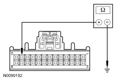
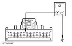
| F3 CHECK CIRCUIT GD116 (BK/VT) FOR AN OPEN | |
NOTE: Failure to disconnect the battery will result in false resistance readings. 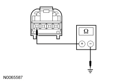 | Yes
GO to F4 . No REPAIR circuit GD116 (BK/VT) for an open. CLEAR the DTCs. REPEAT the self-test. TEST the system for normal operation. |
| F4 CHECK CIRCUIT VH417 (YE/OG) OR CIRCUIT VH416 (VT/GY) FOR AN OPEN | |
  | Yes
GO to F6 . No REPAIR circuit VH416 (VT/GY) or circuit VH417 (YE/OG) for an open. CLEAR the DTCs. REPEAT the self-test. TEST the system for normal operation. |
| F5 CHECK CIRCUIT VH417 (YE/OG) OR VH416 (VT/GY) FOR A SHORT TO GROUND | |
 | Yes
GO to F6 . No REPAIR circuits VH417 (YE/OG) and VH416 (VT/GY) for a short to circuit RH111 (GY/BU). CLEAR the DTCs. REPEAT the self-test. TEST the system for normal operation. |
| F6 CHECK THE HVAC MODULE CONNECTION | |
| Yes
INSTALL a new HVAC module. REFER to Section 412-01 . TEST the system for normal operation. No The system is operating correctly at this time. The concern may have been caused by a loose or corroded connector. CLEAR the DTCs. REPEAT the self-test. TEST the system for normal operation. |
Pinpoint Test G: DTCs B1B71:11 and B1B71:15
Refer to Wiring Diagrams Cell 54 , Manual Climate Control System for schematic and connector information.
Refer to Wiring Diagrams Cell 55 , Automatic Climate Control System for schematic and connector information.
Under normal operation, the evaporator discharge air temperature sensor receives a ground from the HVAC module. The sensor varies its resistance with the temperature. As the temperature rises, the resistance falls. As the temperature falls, the resistance rises. The HVAC module measures this resistance to determine the temperature at the sensor.
The evaporator temperature sensor is used for A/C compressor cycling. An accurate evaporator temperature is critical to prevent evaporator icing. The temperature measurement is used by the HVAC module to turn off the A/C compressor before the evaporator temperatures are cold enough to freeze the condensation. This prevents ice blockage of airflow over the evaporator core.
| Test Step | Result / Action to Take | ||||||||||||||||||||||
|---|---|---|---|---|---|---|---|---|---|---|---|---|---|---|---|---|---|---|---|---|---|---|---|
| G1 CHECK THE SENSOR RESISTANCE | |||||||||||||||||||||||
 | Yes
GO to G2 . No INSTALL an evaporator discharge air temperature sensor. CLEAR the DTCs. REPEAT the self-test. TEST the system for normal operation. | ||||||||||||||||||||||
| G2 CHECK THE SENSOR OUTPUT VOLTAGE | |||||||||||||||||||||||
 | Yes
GO to G8 . No For DTC B1B71:15 , GO to G3 . For DTC B1B71:11 , GO to G6 . | ||||||||||||||||||||||
| G3 CHECK CIRCUIT VH406 (VT/BN) FOR A SHORT TO VOLTAGE | |||||||||||||||||||||||
 | Yes
REPAIR circuit VH406 (VT/BN) for a short to voltage. CLEAR the DTCs. REPEAT the self-test. TEST the system for normal operation. No GO to G4 . | ||||||||||||||||||||||
| G4 CHECK CIRCUIT VH406 (VT/BN) FOR AN OPEN | |||||||||||||||||||||||
 | Yes
GO to G5 . No REPAIR circuit VH406 (VT/BN) for an open. CLEAR the DTCs. REPEAT the self-test. TEST the system for normal operation. | ||||||||||||||||||||||
| G5 CHECK CIRCUIT RH111 (GY/BU) FOR AN OPEN | |||||||||||||||||||||||
 | Yes
GO to G8 . No REPAIR circuit RH111 (GY/BU) for an open. CLEAR the DTCs. REPEAT the self-test. TEST the system for normal operation. | ||||||||||||||||||||||
| G6 CHECK CIRCUIT VH406 (VT/BN) FOR A SHORT TO CIRCUIT RH111 (GY/BU) | |||||||||||||||||||||||
 | Yes
GO to G7 . No REPAIR circuit VH406 (VT/BN) for a short to circuit RH111 (GY/BU). CLEAR the DTCs. REPEAT the self-test. TEST the system for normal operation. | ||||||||||||||||||||||
| G7 CHECK CIRCUIT VH406 (VT/BN) FOR A SHORT TO GROUND | |||||||||||||||||||||||
 | Yes
GO to G8 . No REPAIR circuit VH406 (VT/BN) for a short to ground. CLEAR the DTCs. REPEAT the self-test. TEST the system for normal operation. | ||||||||||||||||||||||
| G8 CHECK THE HVAC MODULE CONNECTION | |||||||||||||||||||||||
| Yes
INSTALL a new HVAC module. REFER to Section 412-01 . TEST the system for normal operation. No The system is operating correctly at this time. The concern may have been caused by a loose or corroded connector. CLEAR the DTCs. REPEAT the self-test. TEST the system for normal operation. |
Pinpoint Test H: DTCs U3003:16 and U3003:17
Refer to Wiring Diagrams Cell 54 , Manual Climate Control System for schematic and connector information.
Refer to Wiring Diagrams Cell 55 , Automatic Climate Control System for schematic and connector information.
NOTE: DTC U3003 can be set if the vehicle has been recently jump started, the battery has been recently charged or the battery has been discharged. The battery may become discharged due to excessive load(s) on the charging system from aftermarket accessories or if the battery has been left unattended with the accessories on.
NOTE: Carry out a thorough inspection and verification before proceeding with the pinpoint test. Refer to Inspection and Verification in this section.
Under normal operation, the HVAC module receives a ground through circuit GD116 (BK/VT). The HVAC module is supplied constant battery voltage through circuit SBP15 (WH/RD).
| Test Step | Result / Action to Take |
|---|---|
| H1 RETRIEVE ALL CMDTCs IN ALL MODULES | |
| Yes
REFER to Section 414-00 for diagnosis of the battery and charging system. No GO to H2 . |
| H2 CHECK BATTERY CONDITION | |
| Yes
If the battery passed the condition test but required a recharge, REFER to Section 414-00 to diagnose the charging system. CLEAR all Continuous Memory Diagnostic Trouble Codes (CMDTCs). TEST the system for normal operation. If the battery passed the condition test and did not require a recharge, GO to H3 . No INSTALL a new battery. CLEAR all CMDTCs . TEST the system for normal operation. |
| H3 CHECK THE CHARGING SYSTEM VOLTAGE | |
NOTE: Do not allow the engine rpm to increase above 2,000 rpm while performing this step or the generator may self excite and result in default charging system output voltage. If engine rpm has gone above 2,000 rpm, shut the vehicle OFF and restart the engine before performing this step. 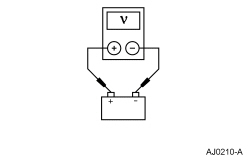 | Yes
For DTC U3003:17 , GO to H4 . For DTC U3003:16 , INSTALL a new HVAC module. REFER to Section 412-01 . CLEAR all CMDTCs . REPEAT the self-test. No REFER to Section 414-00 to diagnose the charging system. CLEAR all CMDTCs . TEST the system for normal operation. |
| H4 CHECK CIRCUITS SBP15 (WH/RD) FOR AN OPEN | |
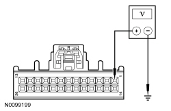 | Yes
GO to H5 . No VERIFY Smart Junction Box (SJB) fuse 15 (10A) is OK. If OK, REPAIR circuit SBP15 (WH/RD) for an open. CLEAR all CMDTCs . REPEAT the self-test. If not OK, REFER to the Wiring Diagrams manual to identify the possible causes of the circuit short. |
| H5 CHECK CIRCUIT GD133 (BK) FOR AN OPEN | |
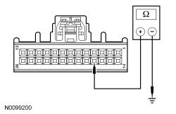 | Yes
GO to H6 . No REPAIR circuit GD116 (BK/VT) for an open. TEST the system for normal operation. |
| H6 CHECK THE HVAC MODULE CONNECTION | |
| Yes
INSTALL a new HVAC module. REFER to Section 412-01 . TEST the system for normal operation. No The system is operating correctly at this time. The concern may have been caused by a loose or corroded connector. CLEAR the DTCs. REPEAT the self-test. TEST the system for normal operation. |
Pinpoint Test I: Unable To Duplicate The Customers Concern and No DTCs Present
NOTE: Diagnose any HVAC module DTCs before carrying out the following pinpoint test.
NOTE: Some PCM DTCs may inhibit A/C operation. If any PCM DTCs are retrieved, diagnose those first. Refer to PCM DTC Chart.
| Test Step | Result / Action to Take |
|---|---|
| I1 CHECK THE BLOWER MOTOR OPERATION | |
| Yes
GO to I2 . No If the blower motor does not operate in any setting, GO to Pinpoint Test Q . If the blower motor does not properly change speeds or shut OFF, GO to Pinpoint Test R . |
| I2 CHECK AIRFLOW OPERATION | |
| Yes
GO to I3 . No GO to Pinpoint Test K . |
| I3 VERIFY TEMPERATURE CONTROL OPERATION | |
| Yes
GO to I4 . No If the temperature does not get very warm, GO to Pinpoint Test L . If the temperature does not change at all, GO to Pinpoint Test P . |
| I4 VERIFY THE A/C CLUTCH DOES NOT ENGAGE WITH A/C OFF | |
| Yes
GO to I5 . No If the temperature is warmer than ambient temperature, GO to Pinpoint Test P and diagnose for inoperative blend door. If the outlet temperature is significantly colder than ambient temperature and the A/C compressor clutch cycles normally, GO to Pinpoint Test O . If the outlet temperature is significantly colder than ambient temperature and the A/C compressor clutch does not cycle, GO to Pinpoint Test N . |
| I5 VERIFY A/C CLUTCH ENGAGEMENT IN THE A/C MODE | |
| Yes
GO to I6 . No GO to Pinpoint Test M . |
| I6 CHECK THE RECIRC OPERATION | |
| Yes
For Electronic Manual Temperature Control (EMTC) equipped vehicles, the system is operating normally. For Dual Automatic Temperature Control (DATC) equipped vehicles, GO to I7 . No GO to Pinpoint Test J . |
| I7 CHECK IN-VEHICLE TEMPERATURE SENSOR FAN OPERATION | |
| Yes
The system is operating normally. No GO to Pinpoint Test S . |
Pinpoint Test J: The Air Inlet Door is Inoperative
Refer to Wiring Diagrams Cell 54 , Manual Climate Control System for schematic and connector information.
Refer to Wiring Diagrams Cell 55 , Automatic Climate Control System for schematic and connector information.
Under normal operation, to rotate the air inlet mode door actuator, the HVAC module supplies voltage and ground to the air inlet mode door actuator through the actuator motor circuits. To reverse the air inlet mode door actuator rotation, the HVAC module reverses the voltage and ground circuits.
| Test Step | Result / Action to Take |
|---|---|
| J1 CHECK THE HVAC MODULE FOR DTCs | |
| Yes
For DTC B1083:00 , GO to J4 . For DTC B1083:11 , GO to J2 . For DTC B1083:12 , GO to J3 . No INSPECT for broken/binding linkage or door. REPAIR as necessary. If no condition is found, GO to J6 . |
| J2 CHECK CIRCUITS CH207 (BU/GY) AND CH208 (GN/OG) FOR A SHORT TO GROUND | |
 | Yes
GO to J5 . No REPAIR circuit CH207 (BU/GY) or CH208 (GN/OG) for a short to ground. CLEAR the DTCs. REPEAT the self-test. TEST the system for normal operation. |
| J3 CHECK CIRCUITS CH207 (BU/GY) AND CH208 (GN/OG) FOR A SHORT TO VOLTAGE | |
 | Yes
REPAIR circuit CH207 (BU/GY) or CH208 (GN/OG) for a short to voltage. CLEAR the DTCs. REPEAT the self-test. TEST the system for normal operation. No GO to J5 . |
| J4 CHECK THE ACTUATOR MOTOR DRIVE CIRCUITS FOR AN OPEN | |
  | Yes
GO to J6 . No REPAIR the circuit(s) for an open. TEST the system for normal operation. |
| J5 CHECK CIRCUIT CH207 (BU/GY) FOR A SHORT TO CIRCUIT CH208 (GN/OG) | |
 | Yes
GO to J6 . No REPAIR circuit CH208 (GN/OG) for a short to circuit CH207 (BU/GY). CLEAR the DTCs. REPEAT the self-test. TEST the system for normal operation. |
| J6 CHECK THE ACTUATOR CONNECTION | |
| Yes
CARRY OUT the Air Inlet Mode Door Actuator component test in this section. If the actuator tests OK, GO to J7 . No The system is operating correctly at this time. The concern may have been caused by a loose or corroded connector. CLEAR the DTCs. TEST the system for normal operation. |
| J7 CHECK THE HVAC MODULE CONNECTION | |
| Yes
INSTALL a new HVAC module. REFER to Section 412-01 . TEST the system for normal operation. No The system is operating correctly at this time. The concern may have been caused by a loose or corroded connector. CLEAR the DTCs. REPEAT the self-test. TEST the system for normal operation. |
Pinpoint Test K: Incorrect/Erratic Direction of Airflow From Outlets
Refer to Wiring Diagrams Cell 54 , Manual Climate Control System for schematic and connector information.
Refer to Wiring Diagrams Cell 55 , Automatic Climate Control System for schematic and connector information.
Under normal operation, to rotate the panel/defrost mode door actuator, the HVAC module supplies voltage or ground to the defrost/panel mode door actuator motor through circuits. To reverse the panel/defrost mode door actuator rotation, the HVAC module reverses the voltage and ground circuits.
The panel/defrost mode door actuator feedback resistor is supplied a 5-volt reference voltage and ground from the HVAC module. The HVAC module measures the resistance on the panel/defrost mode door actuator feedback circuit to determine the panel/defrost mode door actuator position by the position of the actuator feedback resistor wiper arm.
To rotate the floor mode door actuator, the HVAC module supplies voltage or ground to the floor mode door actuator motor through circuits. To reverse the floor mode door actuator rotation, the HVAC module reverses the voltage and ground circuits. The floor mode door actuator is not equipped with a feedback resistor.
During an actuator calibration cycle, the HVAC module drives the panel/defrost mode door until the door reaches both internal stops in the HVAC case. If the panel/defrost mode door is temporarily obstructed or binding during a calibration cycle, the HVAC module may interpret this as the actual end of travel for the door. When this condition occurs and the HVAC module commands the actuator to its end of travel, the airflow may not be from the expected outlets.
| DTC Description | Fault Trigger Conditions |
|---|---|
| The module senses no changes in the feedback circuit when motor movement is commanded and no motor DTCs are present, indicating an open circuit or mechanical failure. |
| The module senses lower than expected voltage on an actuator motor circuit when voltage is applied to drive the motor, indicating a short to ground. |
| The module senses greater than expected voltage on the actuator motor circuit when ground is applied to drive the motor, indicating a short to voltage. |
| The module senses lower than expected voltage on the actuator feedback circuit, indicating a short to ground. |
| The module senses greater than expected voltage on the actuator feedback circuit, indicating an open circuit or a short to voltage. |
| The module senses no voltage on the actuator motor ground circuit when the motor is not commanded ON, indicating an open circuit or internal electrical failure. |
| The module senses lower than expected voltage on an actuator motor circuit when voltage is applied to drive the motor, indicating a short to ground. |
| The module senses greater than expected voltage on the actuator motor circuit when ground is applied to drive the motor, indicating a short to voltage. |
| Test Step | Result / Action to Take |
|---|---|
| K1 CHECK THE HVAC MODULE FOR DTCs | |
| Yes
For DTC B1086:00 , INSPECT for binding/damaged linkage or door. REPAIR as necessary. If no condition is found, GO to K4 . For DTC B125B:00 , INSPECT for binding/damaged linkage or door. REPAIR as necessary. If no condition is found, GO to K13 . For DTC B1086:11 or DTC B125B:11 , GO to K2 . For DTC B1086:12 or DTC B125B:12 , GO to K3 . For DTC B11E7:11 , GO to K6 . For DTC B11E7:15 , GO to K8 . No INSPECT for broken linkage or door. REPAIR as necessary. If no condition is found, GO to K14 . |
| K2 CHECK THE ACTUATOR MOTOR DRIVE CIRCUITS FOR A SHORT TO GROUND | |
For DTC B1086:11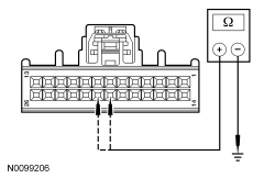 For DTC B125B:11 | Yes
GO to K5 . No REPAIR the circuit CH228 (YE/GY) or CH229 (WH/BU) for a short to ground. TEST the system for normal operation. |
| K3 CHECK THE ACTUATOR MOTOR DRIVE CIRCUITS FOR A SHORT TO VOLTAGE | |
For DTC B1086:12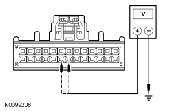 For DTC B125B:12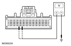 | Yes
REPAIR the circuit CH228 (YE/GY) or CH229 (WH/BU) for a short to voltage. TEST the system for normal operation. No GO to K5 . |
| K4 CHECK THE ACTUATOR MOTOR DRIVE CIRCUITS FOR AN OPEN | |
  | Yes
GO to K14 . No REPAIR the circuit CH228 (YE/GY) or CH229 (WH/BU) for an open. TEST the system for normal operation. |
| K5 CHECK THE ACTUATOR MOTOR DRIVE CIRCUITS FOR A SHORT TOGETHER | |
For DTC B1086:11 and 12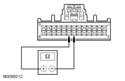 For DTC B125B:11 and 12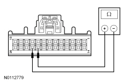 | Yes
GO to K14 . No REPAIR circuits CH228 (YE/GY) and CH229 (WH/BU) for a short together. TEST the system for normal operation. |
| K6 CHECK CIRCUIT VH436 (YE/VT) FOR A SHORT TO GROUND | |
 | Yes
GO to K7 . No REPAIR circuit VH436 (YE/VT) for a short to ground. TEST the system for normal operation. |
| K7 CHECK CIRCUIT RH111 (GY/BU) FOR A SHORT TO CIRCUIT VH436 (YE/VT) | |
 | Yes
GO to K14 . No REPAIR circuits RH111 (GY/BU) and VH436 (YE/VT) for a short together. TEST the system for normal operation. |
| K8 CHECK CIRCUIT VH436 (YE/VT) FOR A SHORT TO VOLTAGE | |
 | Yes
REPAIR circuit VH436 (YE/VT) for a short to voltage. TEST the system for normal operation. No GO to K9 . |
| K9 CHECK CIRCUIT LH111 (BN/WH) FOR A SHORT TO CIRCUIT VH436 (YE/VT) | |
 | Yes
GO to K10 . No REPAIR circuits LH111 (BN/WH) and VH436 (YE/VT) for a short together. TEST the system for normal operation. |
| K10 CHECK CIRCUIT VH436 (YE/VT) FOR AN OPEN | |
 | Yes
GO to K11 . No REPAIR circuit VH436 (YE/VT) for an open. TEST the system for normal operation. |
| K11 CHECK THE ACTUATOR RETURN CIRCUIT RH111 (GY/BU) FOR AN OPEN | |
 | Yes
GO to K12 . No REPAIR circuit RH111 (GY/BU) for an open. TEST the system for normal operation. |
| K12 CHECK CIRCUIT LH111 (BN/WH) FOR AN OPEN | |
 | Yes
GO to K14 . No REPAIR circuit LH111 (BN/WH) for an open. TEST the system for normal operation. |
| K13 CHECK THE ACTUATOR MOTOR DRIVE CIRCUITS FOR AN OPEN | |
  | Yes
GO to K14 . No REPAIR the circuit CH202 (BU/GN) or CH203 (GN/BN) for an open. TEST the system for normal operation. |
| K14 CHECK THE ACTUATOR CONNECTION | |
| Yes
CARRY OUT the Panel/Defrost Mode Door Actuator or Floor Mode Door Actuator component test in this section. If the actuator tests OK, GO to K15 . No The system is operating correctly at this time. The concern may have been caused by a loose or corroded connector. CLEAR the DTCs. TEST the system for normal operation. |
| K15 MODULE ACTUATOR POSITION CALIBRATION | |
NOTE: The purpose of the module actuator position calibration is to allow the HVAC module to reinitialize and calibrate the actuator stop points. To carry out the calibration, follow the steps below. | Yes
INSTALL a new HVAC module. REFER to Section 412-01 . TEST the system for normal operation. No The system is now operating correctly at this time. The concern may have been caused by a foreign object in the HVAC case or temporary binding that restricted actuator door travel. CHECK any actuator external linkage. If condition recurs, INSPECT actuator linkage and door for binding and CHECK HVAC case for foreign objects. |
Pinpoint Test L: Insufficient, Erratic or No Heat
Under normal operation, warm coolant flows from the engine through the heater core and back to the engine.
| Test Step | Result / Action to Take |
|---|---|
| L1 CHECK FOR CORRECT ENGINE COOLANT LEVEL | |
| Yes
GO to L3 . No GO to L2 . |
| L2 CHECK THE ENGINE COOLING SYSTEM FOR LEAKS | |
| Yes
REPAIR the engine coolant leak. TEST the system for normal operation. No FILL and BLEED the cooling system. REFER to Section 303-03A or Section 303-03B . After filling and bleeding the cooling system, GO to L3 . |
| L3 CHECK FOR COOLANT FLOW TO THE HEATER CORE | |
| Yes
GO to L4 . No REFER to Section 303-03A or Section 303-03B to check cooling system function. |
| L4 CHECK FOR A PLUGGED OR RESTRICTED HEATER CORE | |
| Yes
GO to Pinpoint Test P and diagnose for a temperature blend door actuator. No INSTALL a new heater core. TEST the system for normal operation. |
Pinpoint Test M: The Air Conditioning (A/C) is Inoperative
Refer to Wiring Diagrams Cell 54 , Manual Climate Control System for schematic and connector information.
Refer to Wiring Diagrams Cell 55 , Automatic Climate Control System for schematic and connector information.
Under normal operation, when the A/C button is pressed, a message is sent from the Front Controls Interface Module (FCIM) over the Medium Speed Controller Area Network (MS-CAN) bus to the HVAC module. The HVAC module then sends an A/C request message over the MS-CAN bus to the Instrument Cluster (IC), then from the IC through the High Speed Controller Area Network (HS-CAN) bus to the PCM.
For all vehicles equipped with navigation , when MAX A/C is selected on the touch screen, the Audio Front Control Module (ACM) sends a message over the MS-CAN bus to the HVAC module that MAX A/C has been selected.
Voltage is provided to the A/C clutch relay coil and switch contacts. When A/C is requested and A/C line pressures allow, a ground is provided to the A/C clutch relay coil from the PCM, energizing the A/C clutch relay. When the PCM energizes the relay, voltage is supplied to the A/C clutch from the relay. Ground is supplied for the A/C clutch.
The evaporator temperature sensor is used for A/C compressor cycling. An accurate evaporator temperature is critical for compressor engagement. The temperature measurement is used by the PCM to turn off the A/C compressor before the evaporator temperatures are cold enough to freeze the condensation.
When an A/C request is received by the PCM, the A/C compressor clutch will only be engaged through the A/C clutch relay if all of the following conditions are met:
NOTE: Before carrying out the following test, diagnose any HVAC, PCM, ACM , FCIM or IC DTCs.
NOTE: Before carrying out the following test, check that the A/C system pressure is above 290 kPa (42 psi). If the pressure is below 290 kPa (42 psi), refer to Fluorescent Dye Leak Detection in this section.
| Test Step | Result / Action to Take |
|---|---|
| M1 CHECK THE A/C PRESSURE SENSOR (ACP_PRESS) PCM PID | |
| Yes
GO to M2 . No INSTALL a new A/C pressure transducer. TEST the system for normal operation. |
| M2 CHECK THE A/C EVAPORATOR TEMPERATURE (EVAP_TEMP) HVAC PID | |
| Yes
GO to M3 . No INSTALL a new Evaporator discharge air temperature sensor. TEST the system for normal operation. |
| M3 CHECK THE (A/C) SWITCH (CC_SW_AC) FCIM PID WITH THE A/C ON | |
| Yes
GO to M4 . No INSTALL a new FCIM . TEST the system for normal operation. |
| M4 CHECK THE AIR CONDITIONING REQUEST SIGNAL (AC_REQ) PCM PID WITH THE A/C ON | |
| Yes
For vehicles equipped with navigation, GO to M5 . For vehicles not equipped with navigation, GO to M6 . No GO to M16 . |
| M5 CHECK THE AIR CONDITIONING REQUEST SIGNAL (AC_REQ) PCM PID WITH MAX A/C OPERATION | |
| Yes
GO to M6 . No INSTALL a new ACM . TEST the system for normal operation. |
| M6 CHECK THE AIR CONDITIONING COMPRESSOR COMMANDED STATE (ACC_CMD) PCM PID WITH THE A/C ON | |
| Yes
GO to M7 . No GO to M17 . |
| M7 CHECK THE VOLTAGE AT THE A/C COMPRESSOR CLUTCH FIELD COIL | |
 | Yes
GO to M8 . No CARRY OUT the A/C clutch relay component test. Refer to Wiring Diagrams Cell 149 for component testing. If the relay tests OK, GO to M11 . |
| M8 CHECK THE GROUND AT THE A/C COMPRESSOR CLUTCH FIELD COIL | |
 | Yes
GO to M9 . No REPAIR circuit GD123 (BK/GY) for an open. TEST the system for normal operation. |
| M9 CHECK THE A/C COMPRESSOR CLUTCH FIELD COIL | |
| Yes
GO to M10 . No INSTALL a new A/C compressor clutch field coil. TEST the system for normal operation. |
| M10 CHECK THE A/C COMPRESSOR CLUTCH FIELD COIL FOR A SHORT TO GROUND | |
| Yes
ADJUST the A/C compressor clutch gap. REFER to Air Conditioning (A/C) Clutch Air Gap Adjustment in this section. TEST the system for normal operation. No INSTALL a new A/C compressor clutch field coil. TEST the system for normal operation. |
| M11 CHECK THE VOLTAGE TO THE A/C CLUTCH RELAY SWITCH CONTACTS | |
 | Yes
GO to M12 . No VERIFY Battery Junction Box (BJB) fuse 25 (10A) is OK. If OK, REPAIR circuit SBB25 (RD) for an open. TEST the system for normal operation. If not OK, REFER to the Wiring Diagrams manual to identify the possible causes of the circuit short. |
| M12 CHECK THE VOLTAGE TO THE A/C CLUTCH RELAY COIL | |
| Yes
GO to M13 . No REPAIR circuit CBB46 (WH/BU) for an open. CLEAR the DTCs. REPEAT the self-test. TEST the system for normal operation. |
| M13 CHECK CIRCUIT CH401 (VT/WH) FOR AN OPEN | |
 | Yes
GO to M14 . No REPAIR circuit CH401 (VT/WH) for an open. CLEAR the DTCs. REPEAT the self-test. TEST the system for normal operation. |
| M14 CHECK CIRCUIT CH302 (WH/BN) FOR A SHORT TO VOLTAGE | |
| Yes
REPAIR circuit CH302 (WH/BN) for a short to voltage. CLEAR the DTCs. REPEAT the self-test. TEST the system for normal operation. No GO to M15 . |
| M15 CHECK CIRCUIT CH302 (WH/BN) FOR AN OPEN | |
| Yes
GO to M17 . No REPAIR circuit CH302 (WH/BN) for an open. CLEAR the DTCs. REPEAT the self-test. TEST the system for normal operation. |
| M16 CHECK THE HVAC MODULE CONNECTION | |
| Yes
INSTALL a new HVAC module. REFER to Section 412-01 . TEST the system for normal operation. If the condition returns, GO to M13 . No The system is operating correctly at this time. The concern may have been caused by a loose or corroded connector. CLEAR the DTCs. REPEAT the self-test. TEST the system for normal operation. |
| M17 CHECK THE PCM CONNECTION | |
| Yes
INSTALL a new PCM. TEST the system for normal operation. No The system is operating correctly at this time. The concern may have been caused by a loose or corroded connector. |
Pinpoint Test N: The Air Conditioning (A/C) is Always On — A/C Compressor Does Not Cycle
Refer to Wiring Diagrams Cell 54 , Manual Climate Control System for schematic and connector information.
Refer to Wiring Diagrams Cell 55 , Automatic Climate Control System for schematic and connector information.
Under normal operation, when the A/C button is pressed, a message is sent from the Front Controls Interface Module (FCIM) over the Medium Speed Controller Area Network (MS-CAN) bus to the HVAC module. The HVAC module then sends an A/C request message over the MS-CAN bus to the Instrument Cluster (IC), then from the IC through the High Speed Controller Area Network (HS-CAN) bus to the PCM.
For all vehicles equipped with navigation , when MAX A/C is selected on the touch screen, the Audio Front Control Module (ACM) sends a message over the MS-CAN bus to the HVAC module that MAX A/C has been selected.
Voltage is provided to the A/C clutch relay coil and switch contacts. When A/C is requested and A/C line pressures allow, a ground is provided to the A/C clutch relay coil from the PCM, energizing the A/C clutch relay. When the PCM energizes the relay, voltage is supplied to the A/C clutch from the relay. Ground is supplied for the A/C clutch.
The evaporator discharge air temperature sensor is used for A/C compressor cycling. An accurate evaporator discharge air temperature is critical to prevent evaporator icing. The temperature measurement is used by the HVAC module to turn off the A/C compressor when the evaporator temperatures are cold enough to freeze the condensation. This prevents ice blockage of airflow over the evaporator core.
NOTE: Before carrying out the following test, diagnose any HVAC, PCM or IC DTCs.
| Test Step | Result / Action to Take |
|---|---|
| N1 CHECK THE A/C EVAPORATOR TEMPERATURE (EVAP_TEMP) HVAC PID | |
| Yes
GO to N2 . No INSTALL a new evaporator discharge temperature sensor. TEST the system for normal operation. |
| N2 CHECK THE AIR CONDITIONING COMPRESSOR COMMANDED STATE (ACC_CMD) PCM PID WITH THE A/C OFF | |
| Yes
GO to N3 . No GO to N6 . |
| N3 CHECK FOR VOLTAGE TO THE A/C COMPRESSOR CLUTCH FIELD COIL | |
| Yes
CARRY OUT the A/C clutch relay component test. Refer to Wiring Diagrams Cell 149 for component testing. If the relay tests OK, GO to N4 .No ADJUST the A/C compressor clutch gap. REFER to Air Conditioning (A/C) Clutch Air Gap Adjustment in this section. TEST the system for normal operation. |
| N4 CHECK CIRCUIT CH401 (VT/WH) FOR A SHORT TO VOLTAGE | |
| Yes
REPAIR circuit CH401 (VT/WH) for a short to voltage. TEST the system for normal operation. No GO to N5 |
| N5 CHECK CIRCUIT CH302 (WH/BN) FOR A SHORT TO GROUND | |
| Yes
GO to N6 . No REPAIR circuit CH302 (WH/BN) for a short to ground. CLEAR the DTCs. REPEAT the self-test. TEST the system for normal operation. |
| N6 CHECK THE PCM CONNECTION | |
| Yes
INSTALL a new PCM. TEST the system for normal operation. No The system is operating correctly at this time. The concern may have been caused by a loose or corroded connector. |
Pinpoint Test O: The Air Conditioning (A/C) is Always On — A/C Mode Always Commanded ON
Refer to Wiring Diagrams Cell 54 , Manual Climate Control System for schematic and connector information.
Refer to Wiring Diagrams Cell 55 , Automatic Climate Control System for schematic and connector information.
Under normal operation, when the A/C button is pressed, a message is sent from the Front Controls Interface Module (FCIM) over the Medium Speed Controller Area Network (MS-CAN) bus to the HVAC module. The HVAC module then sends an A/C request message over the MS-CAN bus to the Instrument Cluster (IC), then from the IC through the High Speed Controller Area Network (HS-CAN) bus to the PCM.
For all vehicles equipped with navigation , when MAX A/C is selected on the touch screen, the Audio Front Control Module (ACM) sends a message over the MS-CAN bus to the HVAC module that MAX A/C has been selected.
NOTE: Before carrying out the following test, diagnose any HVAC, PCM or IC DTCs.
| Test Step | Result / Action to Take |
|---|---|
| O1 CHECK THE AIR CONDITIONING SWITCH STATUS (CC_SW_AC) HVAC PID WITH THE A/C OFF | |
| Yes
GO to O2 . No INSTALL a new Front Controls Interface Module (FCIM). TEST the system for normal operation. |
| O2 CHECK THE AIR CONDITIONING REQUEST SIGNAL (AC_REQ) PCM PID WITH THE A/C OFF | |
| Yes
GO to O5 . No GO to O3 . |
| O3 CHECK THE AIR CONDITIONING REQUEST SIGNAL (AC_REQ) PCM PID WITH HVAC MODULE DISCONNECTED | |
| Yes
GO to O4 . No GO to O5 . |
| O4 CHECK THE HVAC MODULE CONNECTION | |
| Yes
INSTALL a new HVAC module. REFER to Section 412-01 . TEST the system for normal operation. No The system is operating correctly at this time. The concern may have been caused by a loose or corroded connector. CLEAR the DTCs. REPEAT the self-test. TEST the system for normal operation. |
| O5 CHECK THE PCM CONNECTION | |
| Yes
INSTALL a new PCM. TEST the system for normal operation. No The system is operating correctly at this time. The concern may have been caused by a loose or corroded connector. |
Pinpoint Test P: Temperature Control is Inoperative/Does Not Operate Correctly
Refer to Wiring Diagrams Cell 54 , Manual Climate Control System for schematic and connector information.
Refer to Wiring Diagrams Cell 55 , Automatic Climate Control System for schematic and connector information.
Under normal operation, to rotate the temperature blend door actuator, the HVAC module supplies voltage and ground to the temperature blend door actuator through the door actuator motor circuits. To reverse the temperature blend door actuator rotation, the HVAC module reverses the voltage and ground circuits.
The temperature blend door actuator feedback resistors are supplied a ground from the HVAC module by the temperature blend door actuator return circuits and a 5-volt reference voltage on the temperature blend door actuator reference circuits. The HVAC module reads the voltage on the temperature blend door actuator feedback circuits to determine the temperature blend door actuator position by the position of the actuator feedback resistor wiper arm.
During an actuator calibration cycle, the HVAC module drives the temperature blend door until the door reaches both internal stops in the HVAC case. If the temperature blend door is temporarily obstructed or binding during a calibration cycle, the HVAC module may interpret this as the actual end of travel for the door. When this condition occurs and the HVAC module commands the actuator to its end of travel, the airflow may not be from the expected outlets.
| DTC Description | Fault Trigger Conditions |
|---|---|
| The module senses no changes in the feedback circuit when motor movement is commanded and no motor electrical DTCs are present, indicating an open circuit or mechanical failure. |
| The module senses lower the expected voltage on an actuator motor circuit when voltage is applied to drive the motor, indicating a short to ground. |
| The module senses higher than expected voltage on the actuator motor circuit when ground is applied to drive the motor, indicating a short to voltage. |
| The module senses no changes in the feedback circuit when motor movement is commanded and no motor electrical DTCs are present, indicating an open circuit or mechanical failure. |
| The module senses lower than expected voltage on an actuator motor circuit when voltage is applied to drive the motor, indicating a short to ground. |
| The module senses higher than expected voltage on the actuator motor circuit when ground is applied to drive the motor, indicating a short to voltage. |
| The module senses lower than expected voltage on the actuator feedback circuit, indicating a short to ground. |
| The module senses higher than expected voltage on the actuator feedback circuit, indicating an open circuit or a short to voltage. |
| The module senses lower than expected voltage on the actuator feedback circuit, indicating a short to ground. |
| The module senses higher than expected voltage on the actuator feedback circuit, indicating an open circuit or a short to voltage. |
| Test Step | Result / Action to Take |
|---|---|
| P1 CHECK THE HVAC MODULE FOR DTCs | |
| Yes
For DTC B1081:00 or B1082:00 , INSPECT for binding/damaged linkage or door. REPAIR as necessary. If no condition is found, GO to P3 . For DTC B1081:12 or B1082:12 , GO to P2 . For DTC B1081:11 or B1082:11 , GO to P4 . For DTC B11E5:15 or B11E6:15 , GO to P6 . For DTC B11E5:11 or B11E6:11 , GO to P10 . No INSPECT for broken linkage or door. REPAIR as necessary. If no condition is found, GO to P13 . |
| P2 CHECK THE ACTUATOR MOTOR DRIVE CIRCUITS FOR A SHORT TO POWER | |
  | Yes
REPAIR the circuit(s) for a short to power. CLEAR the DTCs. REPEAT the self-test. TEST the system for normal operation. No GO to P5 . |
| P3 CHECK THE ACTUATOR MOTOR DRIVE CIRCUITS FOR AN OPEN | |
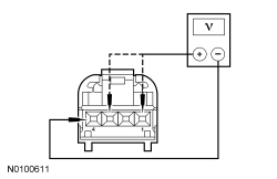
NOTE: Due to limited connector accessibility, before carrying out this test step, visually inspect the wiring between the HVAC module and actuator for opens or shorts. If no damage is visually evident, proceed with the test.  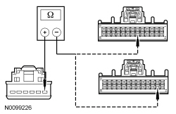 | Yes
GO to P13 . No REPAIR the circuit(s) for an open. CLEAR the DTCs. REPEAT the self-test. TEST the system for normal operation. |
| P4 CHECK THE ACTUATOR MOTOR DRIVE CIRCUITS FOR A SHORT TO GROUND | |
  | Yes
GO to P5 . No REPAIR the circuit(s) for a short to ground. CLEAR the DTCs. REPEAT the self-test. TEST the system for normal operation. |
| P5 CHECK THE ACTUATOR MOTOR DRIVE CIRCUITS FOR A SHORT TOGETHER | |
NOTE: Due to limited connector accessibility, before carrying out this test step, visually inspect the wiring between the HVAC module and actuator for opens or shorts. If no damage is visually evident, proceed with the test. For DTC B1081:11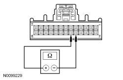 For DTC B1082:11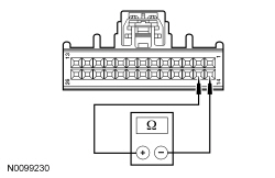 | Yes
GO to P13 . No REPAIR circuit(s) for a short together. CLEAR the DTCs. REPEAT the self-test. TEST the system for normal operation. |
| P6 CHECK CIRCUIT VH441 (WH/BN) OR VH440 (BU/BN) FOR AN OPEN | |
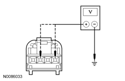
NOTE: Due to limited connector accessibility, before carrying out this test step, visually inspect the wiring between the HVAC module and actuator for opens or shorts. If no damage is visually evident, proceed with the test.  | Yes
GO to P7 . No REPAIR circuit VH441 (WH/BN) or VH440 (BU/BN) for an open. CLEAR the DTCs. REPEAT the self-test. TEST the system for normal operation. |
| P7 CHECK CIRCUIT VH440 (BU/BN) OR VH441 (WH/BN) FOR A SHORT TO POWER | |
 | Yes
REPAIR circuits VH441 (WH/BN) or VH440 (BU/BN) for a short to power. CLEAR the DTCs. REPEAT the self-test. TEST the system for normal operation. No GO to P8 . |
| P8 CHECK CIRCUIT LH111 (BN/WH) FOR A SHORT TO CIRCUIT VH441 (WH/BN) OR VH440 (BU/BN) | |
 | Yes
GO to P9 . No REPAIR circuits LH111 (BN/WH) and VH441 (WH/BN) or VH440 (BU/BN) for a short together. CLEAR the DTCs. REPEAT the self-test. TEST the system for normal operation. |
| P9 CHECK THE ACTUATOR RETURN CIRCUIT RH111 (GY/BU) FOR AN OPEN | |
 | Yes
GO to P13 . No REPAIR circuit RH111 (GY/BU) for an open. CLEAR the DTCs. REPEAT the self-test. TEST the system for normal operation. |
| P10 CHECK CIRCUIT VH440 (BU/BN) OR VH441 (WH/BN) FOR A SHORT TO GROUND | |
 | Yes
GO to P11 . No REPAIR circuit VH441 (WH/BN) or VH440 (BU/BN) for a short to ground. CLEAR the DTCs. REPEAT the self-test. TEST the system for normal operation. |
| P11 CHECK CIRCUIT RH111 (GY/BU) FOR A SHORT TO CIRCUIT VH441 (WH/BN) OR VH440 (BU/BN) | |
NOTE: Due to limited connector accessibility, before carrying out this test step, visually inspect the wiring between the HVAC module and actuator for opens or shorts. If no damage is visually evident, proceed with the test. 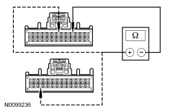 | Yes
GO to P12 . No REPAIR circuits RH111 (GY/BU) and VH441 (WH/BN) or VH440 (BU/BN) for a short together. CLEAR the DTCs. REPEAT the self-test. TEST the system for normal operation. |
| P12 CHECK CIRCUIT LH111 (BN/WH) FOR AN OPEN | |
 | Yes
GO to P13 . No REPAIR circuit LH111 (BN/WH) for an open. CLEAR the DTCs. REPEAT the self-test. TEST the system for normal operation. |
| P13 CHECK THE ACTUATOR CONNECTION | |
| Yes
CARRY OUT the Temperature Blend Door Actuator component test in this section. If the actuator tests OK, GO to P14 . No The system is operating correctly at this time. The concern may have been caused by a loose or corroded connector. CLEAR the DTCs. TEST the system for normal operation. |
| P14 MODULE ACTUATOR POSITION CALIBRATION | |
NOTE: The purpose of the module actuator position calibration is to allow the HVAC module to reinitialize and calibrate the actuator stop points. To carry out the calibration, follow the steps below. | Yes
INSTALL a new HVAC module. REFER to Section 412-01 . TEST the system for normal operation. No The system is now operating correctly at this time. The concern may have been caused by a foreign object in the HVAC case or temporary binding that restricted actuator door travel. CHECK any actuator external linkage. If condition recurs, INSPECT actuator linkage and door for binding and CHECK HVAC case for foreign objects. |
Pinpoint Test Q: The Blower Motor is Inoperative
Refer to Wiring Diagrams Cell 54 , Manual Climate Control System for schematic and connector information.
Refer to Wiring Diagrams Cell 55 , Automatic Climate Control System for schematic and connector information.
Voltage is provided to the blower motor relay coil and switch contacts. When the blower motor relay coil receives a ground from the HVAC module, the relay coil is energized and voltage is delivered from the blower motor relay to the blower motor and the blower motor speed control. A varying ground for the blower motor is provided from the blower motor speed control. Ground is provided for the blower motor speed control. The HVAC module sends a Pulse Width Modulated (PWM) signal to the blower motor speed control to vary the blower speed.
| Test Step | Result / Action to Take |
|---|---|
| Q1 CHECK THE HVAC MODULE FOR DTCs | |
| Yes
For DTC B10AF:12 , REPAIR circuit CH123 (VT/GN) for a short to voltage. CLEAR the DTCs. REPEAT the self-test. TEST the system for normal operation. For DTC B10AF:13 , CARRY OUT the Blower Motor Relay component test. Refer to Wiring Diagrams Cell 149 for component testing. If the relay tests OK, GO to Q2 .For DTC B10B9:14 , GO to Q9 . No GO to Q3 . |
| Q2 CHECK THE RELAY COIL SUPPLY VOLTAGE | |
 | Yes
REPAIR circuit CH123 (VT/GN) for an open. CLEAR the DTCs. REPEAT the self-test. TEST the system for normal operation. No VERIFY Smart Junction Box (SJB) fuse 45 (5A) is OK. If OK, REPAIR circuit CBP45 (YE) for an open. TEST the system for normal operation. If not OK, REFER to the Wiring Diagrams manual to identify the possible causes of the circuit short. |
| Q3 VERIFY THE BLOWER MOTOR OPERATION | |
| Yes
GO to Q4 . No GO to Pinpoint Test R . |
| Q4 CHECK FOR VOLTAGE TO THE BLOWER MOTOR | |
 | Yes
GO to Q5 . No GO to Q11 . |
| Q5 CHECK FOR VOLTAGE TO THE BLOWER MOTOR SPEED CONTROL | |
 | Yes
GO to Q6 . No REPAIR circuit CH402 (YE/GN) for an open. TEST the system for normal operation. |
| Q6 CHECK BLOWER MOTOR SPEED CONTROL GROUND CIRCUIT FOR AN OPEN | |
 | Yes
GO to Q7 . No REPAIR circuit GD114 (BK/BU) for an open. TEST the system for normal operation. |
| Q7 CHECK CIRCUIT CH426 (YE/OG) FOR AN OPEN | |
 | Yes
GO to Q8 . No REPAIR circuit CH426 (YE/OG) for an open. TEST the system for normal operation. |
| Q8 CHECK THE BLOWER MOTOR | |
 | Yes
INSTALL a new blower motor speed control. TEST the system for normal operation. If the blower motor is still inoperative, GO to Q14 . No INSTALL a new blower motor. TEST the system for normal operation. |
| Q9 CHECK CIRCUIT VH101 (WH/VT) FOR A SHORT TO GROUND | |
 | Yes
GO to Q10 . No REPAIR circuit VH101 (WH/VT) for a short to ground. TEST the system for normal operation. |
| Q10 CHECK CIRCUIT VH101 (WH/VT) FOR AN OPEN | |
 | Yes
INSTALL a new blower motor speed control. TEST the system for normal operation. If the blower motor is still inoperative, GO to Q14 . No REPAIR circuit VH101 (WH/VT) for an open. TEST the system for normal operation. |
| Q11 CHECK CIRCUIT CH402 (YE/GN) FOR AN OPEN | |
 | Yes
GO to Q12 . No REPAIR circuit CH402 (YE/GN) for an open. TEST the system for normal operation. |
| Q12 CHECK THE RELAY SWITCH POWER CIRCUIT FOR AN OPEN | |
 | Yes
GO to Q13 . No VERIFY Battery Junction Box (BJB) fuse 4 (30A) is OK. If OK, REPAIR circuit SBB04 (GN/RD) for an open. TEST the system for normal operation. If not OK, REFER to the Wiring Diagrams manual to identify the possible causes of the circuit short. |
| Q13 CHECK THE MODULE OUTPUT | |
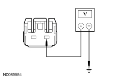
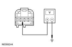
NOTICE: The following step uses the Test Light to simulate normal circuit loads. Use only the Test Light recommended in the Special Tools table at the beginning of this section or equivalent. To avoid connector terminal damage, use the Flex Probe Kit for the Test Light probe connection to the vehicle. Do not use the Test Light probe directly on any connector.  | Yes
INSTALL a new blower motor relay. TEST the system for normal operation. No GO to Q14 . |
| Q14 CHECK THE HVAC MODULE CONNECTION | |
| Yes
INSTALL a new HVAC module. REFER to Section 412-01 . TEST the system for normal operation. No The system is operating correctly at this time. The concern may have been caused by a loose or corroded connector. CLEAR the DTCs. REPEAT the self-test. TEST the system for normal operation. |
Pinpoint Test R: The Blower Motor Does Not Operate Correctly
Refer to Wiring Diagrams Cell 54 , Manual Climate Control System for schematic and connector information.
Refer to Wiring Diagrams Cell 55 , Automatic Climate Control System for schematic and connector information.
Voltage is provided to the blower motor relay coil and switch contacts. When the blower motor relay coil receives a ground from the HVAC module, the relay coil is energized and voltage is delivered from the blower motor relay to the blower motor and the blower motor speed control. A varying ground for the blower motor is provided from the blower motor speed control. Ground is provided for the blower motor speed control. The HVAC module sends a Pulse Width Modulated (PWM) signal to the blower motor speed control to vary the blower speed.
| Test Step | Result / Action to Take |
|---|---|
| R1 VERIFY THE BLOWER MOTOR OPERATION | |
| Yes
If the blower motor operates always in HI, GO to R2 . If the blower motor is always ON, GO to R5 . All other symptoms, GO to R3 . No GO to Pinpoint Test Q . |
| R2 CHECK THE BLOWER MOTOR GROUND CIRCUIT FOR A SHORT TO GROUND | |
| Yes
REPAIR the circuit. No GO to R3 . |
| R3 CHECK THE PWM CIRCUIT FOR A SHORT TO VOLTAGE | |
 | Yes
REPAIR the circuit. No GO to R4 . |
| R4 CHECK THE PWM CIRCUIT FOR AN OPEN | |
| Yes
GO to R5 . No REPAIR the circuit. |
| R5 CHECK THE BLOWER MOTOR RELAY CONTROL CIRCUIT FOR A SHORT TO GROUND | |
 | Yes
GO to R6 . No REPAIR the circuit. |
| R6 CHECK THE BLOWER MOTOR POWER CIRCUIT FOR A SHORT TO VOLTAGE | |
| Yes
REPAIR the circuit. No INSTALL a new blower motor speed control. TEST the system for normal operation. If the blower motor still does not operate correctly, GO to R7 . |
| R7 CHECK THE HVAC MODULE CONNECTION | |
| Yes
INSTALL a new HVAC module. REFER to Section 412-01 . TEST the system for normal operation. No The system is operating correctly at this time. The concern may have been caused by a loose or corroded connector. CLEAR the DTCs. REPEAT the self-test. TEST the system for normal operation. |
Pinpoint Test S: Incorrect/Erratic Function in AUTO Mode
Refer to Wiring Diagrams Cell 55 , Automatic Climate Control System for schematic and connector information.
Under normal operation, the in-vehicle air temperature sensor receives a ground and a 5-volt reference voltage from the HVAC module. To accurately monitor the cabin air temperature, the in-vehicle air temperature sensor uses an integral fan to draw cabin air to the sensor, inside the instrument panel. The fan is supplied voltage and ground.
| Test Step | Result / Action to Take | ||||||||||||||||||
|---|---|---|---|---|---|---|---|---|---|---|---|---|---|---|---|---|---|---|---|
| S1 CHECK IN-VEHICLE TEMPERATURE SENSOR FAN OPERATION | |||||||||||||||||||
| Yes
GO to S2 . No GO to S3 . | ||||||||||||||||||
| S2 CHECK THE SENSOR RESISTANCE | |||||||||||||||||||
| Yes
GO to S5 . No INSTALL a new in-vehicle temperature sensor. TEST the system for normal operation. | ||||||||||||||||||
| S3 CHECK CIRCUIT CBP30 (YE/BU) FOR VOLTAGE | |||||||||||||||||||
 | Yes
GO to S4 . No VERIFY Smart Junction Box (SJB) fuse 30 (5A) is OK. If OK, REPAIR circuit CBP30 (YE/BU) for an open. TEST the system for normal operation. If not OK, REFER to the Wiring Diagrams manual to identify the possible causes of the circuit short. | ||||||||||||||||||
| S4 CHECK CIRCUIT GD114 (BK/BU) FOR GROUND | |||||||||||||||||||
 | Yes
INSTALL a new in-vehicle temperature sensor. TEST the system for normal operation. No REPAIR circuit GD114 (BK/BU) for an open. TEST the system for normal operation. | ||||||||||||||||||
| S5 CHECK THE HVAC MODULE CONNECTION | |||||||||||||||||||
| Yes
INSTALL a new HVAC module. REFER to Section 412-01 . TEST the system for normal operation. No The system is operating correctly at this time. The concern may have been caused by a loose or corroded connector. CLEAR the DTCs. REPEAT the self-test. TEST the system for normal operation. |
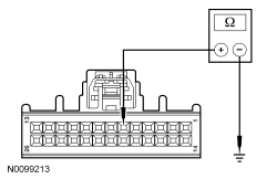
Component Tests
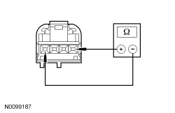
Air Inlet Door Actuator
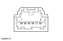
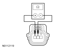
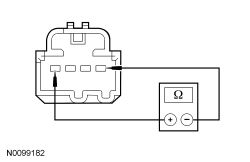
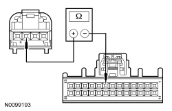
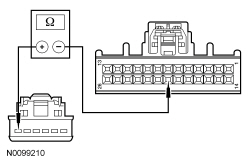
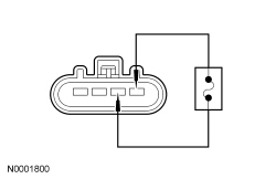
| Actuator Pins | Approx. Resistance |
|---|---|
| 1 and 6 | 65-80 ohms |
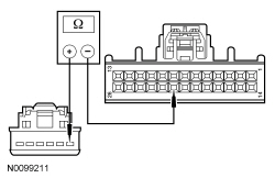
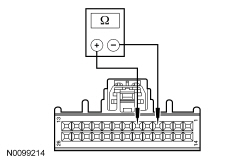
Floor Mode Door Actuator
| Actuator Pins | Approx. Resistance |
|---|---|
| 5 and 6 | 80-97 ohms |
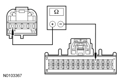
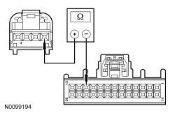
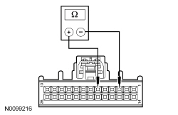
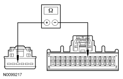
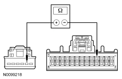
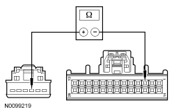
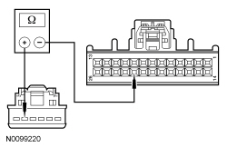
Panel/Defrost Mode Door Actuator
| Actuator Pins | Approx. Resistance |
|---|---|
| 2 and 3 | 2,775-4,625 ohms |
| 2 and 4 | 188-4,313 ohms |
| 3 and 4 | 188-4,313 ohms |
| 1 and 6 | 71-86 ohms |
Blend Mode Door Actuator
| Actuator Pins | Approx. Resistance |
|---|---|
| 2 and 3 | 2,775-4,625 ohms |
| 2 and 4 | 188-4,313 ohms |
| 3 and 4 | 188-4,313 ohms |
| 1 and 6 | 40-50 ohms |
Heater Core
NOTE: If a heater core leak is suspected, the heater core must be tested by carrying out the plugged heater core component test before the heater core pressure test. Carry out a system inspection by checking the heater system thoroughly as follows:
Inspect for evidence of coolant leakage at the heater water hose to heater core attachments. A coolant leak in the heater water hose could follow the heater core tube to the heater core and appear as a leak in the heater core.NOTE: Spring-type clamps are installed as original equipment. Installation and overtightening of non-specification clamps can cause leakage at the heater water hose connection and damage the heater core.
Check the integrity of the heater water hose clamps.Heater Core — Plugged
If the inlet hose is not hot:
If the outlet hose is not hot:
Heater Core — Pressure Test
Use the Pressure Test Kit to carry out the pressure test.
NOTE: Due to space limitations, a bench test may be necessary for pressure testing.
Clamp off the heater hoses. WARNING: Before disconnecting any heater water hoses, shut OFF the engine and wait until engine is fully cool. Failure to comply with this warning may result in serious injury or burns from hot liquid escaping from the engine cooling system.
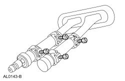
Heater Core — Bench Test
A/C Evaporator/Condenser Core — On Vehicle Leak Test
NOTE: DO NOT leak test an A/C evaporator core with the suction accumulator/drier attached to the core tubes.
Disconnect the suspect A/C evaporator core or A/C condenser core from the A/C system. Refer to Section 412-01 .NOTE: The automatic shut-off valves on some gauge set hoses do not open when connected to the test fittings. If available, use hoses without shut-off valves. If hoses with shut-off valves are used, make sure the valve opens when attached to the test fittings or install an adapter which will activate the valve. The test is not valid if the shut-off valve does not open.
Connect the red and blue hoses from the R-134a Manifold Gauge Set to the test fittings on the A/C evaporator core or A/C condenser core. Connect the yellow hose to a known good vacuum pump.A/C Compressor — External Leak Test