
FLU77-4 or equivalent


105-R025D or equivalent
SECTION 413-00: Instrument Cluster and Panel Illumination
| 2014 Mustang Workshop Manual
|
DIAGNOSIS AND TESTING
| Procedure revision date: 01/07/2013
|
| Fluke 77-IV Digital Multimeter
FLU77-4 or equivalent |
|
Vehicle Communication Module (VCM) and Integrated Diagnostic System (IDS) software with appropriate hardware, or equivalent scan tool
|
| Flex Probe Kit
105-R025D or equivalent |
Principles of Operation
NOTE: The Smart Junction Box (SJB) is also known as the Generic Electronic Module (GEM).
Dimmable Backlighting
When the parking lamps are on, the SJB monitors the input from the instrument panel dimmer switch. The SJB sends a pulse-width modulated voltage to the dimmable components and switches based on input received from the instrument panel dimmer switch.
The SJB also sends a message over the Controller Area Network (CAN) to the Front Controls Interface Module (FCIM), the Front Display Interface Module (FDIM), and the Instrument Panel Cluster (IPC) to indicate the backlighting intensity level. If the receiving module receives invalid backlighting data from the SJB for 5 seconds or less, the receiving module defaults the backlighting to the last setting.
If the receiving module does not receive the backlighting status message from the SJB or if the data received is deemed invalid for more than 5 seconds, the receiving module sets a missing message-related DTC in continuous memory and defaults the backlighting to full nighttime intensity.
Fixed Backlighting
When the accessory delay relay is energized, switched voltage is supplied to the window control switches and the door lock control switches.
Field-Effect Transistor (FET) Protection
Field-Effect Transistor (FET) is a type of transistor that when used with module software can be used to monitor and control current flow on module outputs. The FET protection strategy is used to prevent module damage in the event of excessive current flow.
For a full description of FET protection, refer to Section 419-10 .
Instrument Panel Dimmer Switch Calibration
The instrument panel dimmer switch must be calibrated any time the instrument panel dimmer switch is disconnected or the battery is disconnected or discharged. The switch is calibrated by rotating it from the lowest backlighting setting to the DOME LAMP position.
Inspection and Verification
Visual Inspection Chart
| Mechanical | Electrical |
|---|---|
|
|
NOTE: Make sure to use the latest scan tool release software.
If the cause is not visually evident, connect the scan tool to the Data Link Connector (DLC).NOTE: The Vehicle Communication Module (VCM) LED prove-out confirms power and ground from the DLC are provided to the VCM .
If the scan tool does not communicate with the VCM :DTC Charts
Smart Junction Box (SJB) DTC Chart
| DTC | Description | Action |
|---|---|---|
| B106E | Solid State Driver Disabled Due to Short Circuit | The module has temporarily disabled an output because an excessive current draw exists (such as short to ground). The cause of the excessive current draw MUST be corrected before the SJB will enable the output. After the cause of the concern is corrected, CLEAR the DTCs. REPEAT the self-test. |
| B106F | Module Disabled Due to External Fault | The module has permanently disabled an output because an excessive current draw exists (such as a short to ground) that has exceeded the limits of what the SJB can withstand. The cause of the excessive current draw MUST be corrected before a new SJB is installed. ADDRESS all other DTCs first. After the cause of the concern is corrected, INSTALL a new SJB . REFER to Section 419-10 . TEST the system for normal operation. |
| B2212 | Panel Dim Switch Out of Range | GO to Pinpoint Test B . |
| B2A32 | LED Backlighting Output Circuit Open | If the backlighting components are inoperative,
GO to Pinpoint Test C
.
If the backlighting components are always on, GO to Pinpoint Test D . |
| B2A33 | LED Backlighting Output Circuit Short to Ground | GO to Pinpoint Test C . |
| All other DTCs | — | REFER to the Diagnostic Trouble Code (DTC) Chart in Section 419-10 . |
Symptom Chart
| Condition | Possible Sources | Action |
|---|---|---|
|
| |
|
| |
|
| |
|
| |
|
| |
|
| |
|
|
|
|
|
|
|
|
|
|
|
|
|
|
|
Pinpoint Tests
Pinpoint Test A: All Dimmable Illumination Is Inoperative
Refer to Wiring Diagrams Cell 71 , Cluster and Panel Illumination for schematic and connector information.
The Smart Junction Box (SJB) sends a voltage reference signal to the instrument panel dimmer switch. The signal is routed through a variable resistor within the instrument panel dimmer switch and then back to the SJB through an internal ground. The reference voltage changes depending on the position of the dimmer switch. When the dimmer switch is in the lowest setting, the resistance is low. When the SJB senses the voltage is low (switch in the lowest setting), the dimmable backlighting intensity is low. When the SJB senses the voltage reference is high (switch in the highest setting), the dimmable backlighting intensity is bright. If the signal is too high (an open circuit or short to voltage), the SJB faults the dimmable backlighting to full nighttime brightness. If the dimmer switch input circuit is short to ground, the SJB interprets this as the lowest setting and sets the backlighting to the lowest intensity level, appearing to be inoperative.
Based on the input received from the instrument panel dimmer switch, the SJB sends a message over the network to the backlit modules indicating the backlighting intensity level and a pulse-width modulated voltage to the hardwired dimmable illumination sources.
NOTICE: Use the correct probe adapter(s) when making measurements. Failure to use the correct probe adapter(s) may damage the connector.
| Test Step | Result / Action to Take |
|---|---|
| A1 CHECK FOR RECORDED SJB DTCs FROM THE ON-DEMAND SELF-TEST | |
| Yes
REFER to DTC Charts in this section. No GO to A2 . |
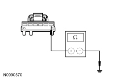
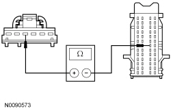
| A2 CHECK THE INSTRUMENT PANEL DIMMER SWITCH | |
| Yes
INSTALL a new instrument panel dimmer switch. REFER to Instrument Panel Dimmer Switch in this section. TEST the system for normal operation. No GO to A3 . |
| A3 CHECK THE INSTRUMENT PANEL DIMMER SWITCH INPUT CIRCUIT FOR A SHORT TO GROUND | |
 | Yes
GO to A4 . No REPAIR circuit VLN18 (BU/WH) for a short to ground. TEST the system for normal operation. |
| A4 CHECK FOR CORRECT SJB OPERATION | |
| Yes
INSTALL a new SJB . REFER to Section 419-10 . TEST the system for normal operation. No The system is operating correctly at this time. The concern may have been caused by a loose or corroded connector. RUN the on-demand self-test (required to clear certain DTCs). CORRECT any unresolved DTCs. CLEAR all DTCs. TEST the system for normal operation. |
Pinpoint Test B: All Dimmable Illumination Does Not Dim
Refer to Wiring Diagrams Cell 71 , Cluster and Panel Illumination for schematic and connector information.
The Smart Junction Box (SJB) sends a voltage reference signal to the instrument panel dimmer switch. The signal is routed through a variable resistor within the instrument panel dimmer switch and then back to the SJB to an internal ground. The reference voltage changes depending on the position of the dimmer switch. When the dimmer switch is in the lowest setting, the resistance is low. When the SJB senses the voltage is low (switch in the lowest setting), the dimmable backlighting intensity is low. When the SJB senses the voltage reference is high (switch in the highest setting), the dimmable backlighting intensity is bright. If the signal is too high (an open circuit or short to voltage), the SJB faults the dimmable backlighting to full nighttime brightness. If the dimmer switch input circuit is short to ground, the SJB interprets this as the lowest setting and sets the backlighting to the lowest intensity level, appearing to be inoperative.
Based on input received from the instrument panel dimmer switch, the SJB sends a message over the network to the backlit modules indicating the backlighting intensity level and a pulse-width modulated voltage to the hardwired dimmable illumination sources.
The SJB also sends a message over the Controller Area Network (CAN) to the Front Controls Interface Module (FCIM), the Front Display Interface Module (FDIM), and the Instrument Panel Cluster (IPC) to indicate the backlighting intensity level. If the receiving module receives invalid backlighting data from the SJB for 5 seconds or less, the receiving module defaults the backlighting to the last setting.
If the receiving module does not receive the backlighting status message from the SJB or if the data received is deemed invalid for more than 5 seconds, the receiving module sets a missing message-related DTC in continuous memory and defaults the backlighting to full nighttime intensity.
NOTICE: Use the correct probe adapter(s) when making measurements. Failure to use the correct probe adapter(s) may damage the connector.
| Test Step | Result / Action to Take |
|---|---|
| B1 CHECK THE INSTRUMENT PANEL DIMMER SWITCH | |
| Yes
GO to B2 . No INSTALL a new instrument panel dimmer switch. REFER to Instrument Panel Dimmer Switch in this section. CLEAR the DTCs. REPEAT the self-test. |
| B2 CHECK THE INSTRUMENT PANEL DIMMER SWITCH INPUT CIRCUIT FOR A SHORT TO VOLTAGE | |
 | Yes
REPAIR circuit VLN18 (BU/WH) for a short to voltage. CLEAR the DTCs. REPEAT the self-test. No GO to B3 . |
| B3 CHECK THE INSTRUMENT PANEL DIMMER SWITCH RETURN CIRCUIT FOR A SHORT TO VOLTAGE | |
 | Yes
REPAIR circuit RLN29 (WH/OG) for a short to voltage. CLEAR the DTCs. REPEAT the self-test. No GO to B4 . |
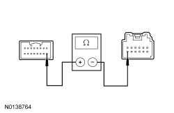
| B4 CHECK THE INSTRUMENT PANEL DIMMER SWITCH INPUT CIRCUIT FOR A SHORT TO GROUND | |
| Yes
GO to B5 . No REPAIR circuit VLN18 (BU/WH) for a short to ground. TEST the system for normal operation. |
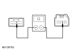
| B5 CHECK THE INSTRUMENT PANEL DIMMER SWITCH INPUT CIRCUIT FOR AN OPEN | |
 | Yes
GO to B6 . No REPAIR circuit VLN18 (BU/WH) for an open. CLEAR the DTCs. REPEAT the self-test. |
| B6 CHECK THE INSTRUMENT PANEL DIMMER SWITCH RETURN CIRCUIT FOR AN OPEN | |
 | Yes
GO to B7 . No REPAIR circuit RLN29 (WH/OG) for an open. CLEAR the DTCs. REPEAT the self-test. |
| B7 CHECK FOR CORRECT SJB OPERATION | |
| Yes
INSTALL a new SJB . REFER to Section 419-10 . TEST the system for normal operation. No The system is operating correctly at this time. The concern may have been caused by a loose or corroded connector. CLEAR the DTCs. REPEAT the self-test. |
Pinpoint Test C: All Dimmable Switch Illumination Is Inoperative
Refer to Wiring Diagrams Cell 71 , Cluster and Panel Illumination for schematic and connector information.
Based on the input received from the instrument panel dimmer switch, the Smart Junction Box (SJB) sends a pulse-width modulated voltage to the hardwired dimmable components.
| DTC Description | Fault Trigger Conditions |
|---|---|
| A continuous DTC that sets when the SJB has temporarily shut down the output driver. The module has temporarily disabled the backlighting output because an excessive current draw exists (such as a short to ground). The SJB cannot enable the backlighting output until the cause of the short is corrected, the DTCs have been cleared and a successful self-test is run. |
| A continuous DTC that sets when the SJB has permanently shut down the output driver. The module has permanently disabled the backlighting output because an excessive current draw fault (such as a short to ground) has exceeded the limits that the SJB can withstand. The cause of the excessive current draw MUST be corrected before a new SJB is installed. |
| An on-demand DTC that sets when the SJB detects an open from the backlighting output circuit. |
| A continuous and on-demand DTC that sets when the SJB detects a short to ground from the backlighting output circuit. The DTC also sets as a result when fuse 10 (15A) has failed or is removed |
NOTICE: Use the correct probe adapter(s) when making measurements. Failure to use the correct probe adapter(s) may damage the connector.
| Test Step | Result / Action to Take |
|---|---|
| C1 CHECK FOR RECORDED SJB DTCs FROM THE ON-DEMAND SELF-TEST | |
| Yes
GO to C2 . No VERIFY the SJB fuse 10 (15A) is OK. If OK, GO to C2 . If not OK, REFER to the Wiring Diagrams Manual to identify the possible causes of the circuit short. After the repair: If no DTCs are present, TEST the system for normal operation. If DTC B106E is present, CLEAR the DTCs and REPEAT the self-test (required to enable the backlighting output driver if DTC B106E is present) . TEST the system for normal operation. If DTC B106F is present, INSTALL a new SJB . REFER to Section 419-10 . TEST the system for normal operation. |
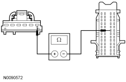
| C2 BYPASS THE SJB | |
NOTE: If the jumper wire fails, refer to the Wiring Diagrams Manual to identify the possible causes of the circuit short. After the repair, if no DTCs are present, test the system for normal operation. If DTC B106E is present, clear the DTCs and repeat the self-test (required to enable the backlighting output driver if DTC B106E is present). Test the system for normal operation. If DTC B106F is present, install a new SJB . Refer to Section 419-10 . Test the system for normal operation. 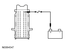 | Yes
REMOVE the jumper wire. GO to C3 . No REMOVE the jumper wire. REPAIR circuit VLN04 (VT/GY) for an open. CLEAR the DTCs. REPEAT the self-test. |
| C3 CHECK FOR CORRECT SJB OPERATION | |
| Yes
INSTALL a new SJB . REFER to Section 419-10 . TEST the system for normal operation. No The system is operating correctly at this time. The concern may have been caused by a loose or corroded connector. CLEAR the DTCs. REPEAT the self-test. |
Pinpoint Test D: All Dimmable Switch Illumination Is Always On
Refer to Wiring Diagrams Cell 71 , Cluster and Panel Illumination for schematic and connector information.
Based on the input received from the instrument panel dimmer switch, the Smart Junction Box (SJB) sends a pulse-width modulated voltage to the hardwired dimmable components.
NOTICE: Use the correct probe adapter(s) when making measurements. Failure to use the correct probe adapter(s) may damage the connector.
| Test Step | Result / Action to Take |
|---|---|
| D1 CHECK THE EXTERIOR LIGHTING | |
| Yes
REFER to Section 417-01 . No GO to D2 . |
| D2 CHECK THE SJB BACKLIGHTING OUTPUT CIRCUIT FOR A SHORT TO VOLTAGE | |
| Yes
REPAIR circuit VLN04 (VT/GY) for a short to voltage. CLEAR the DTCs. REPEAT the self-test. No GO to D3 . |
| D3 CHECK FOR CORRECT SJB OPERATION | |
| Yes
INSTALL a new SJB . REFER to Section 419-10 . TEST the system for normal operation. No The system is operating correctly at this time. The concern may have been caused by a loose or corroded connector. CLEAR the DTCs. REPEAT the self-test. |
Pinpoint Test E: The Steering Wheel Switch Illumination Is Inoperative
Refer to Wiring Diagrams Cell 71 , Cluster and Panel Illumination for schematic and connector information.
When the parking lamps are on, the Smart Junction Box (SJB) sends a pulse-width modulated voltage to the steering wheel switches. The voltage passes through the clockspring to the steering wheel harness and then to the steering wheel control switch(es).
Possible Sources
NOTICE: Use the correct probe adapter(s) when making measurements. Failure to use the correct probe adapter(s) may damage the connector.
| Test Step | Result / Action to Take |
|---|---|
| E1 CHECK THE OTHER DIMMABLE LIGHTING SWITCHES | |
| Yes
GO to Pinpoint Test C . No GO to E2 . |
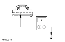
| E2 CHECK FOR VOLTAGE TO THE CLOCKSPRING | |
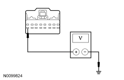 | Yes
GO to E3 . No REPAIR circuit VLN04 (VT/GY) for an open. REPOWER the SRS . REFER to Section 501-20B . TEST the system for normal operation. |
| E3 CHECK FOR VOLTAGE TO THE CLOCKSPRING USING THE CONNECTOR GROUND | |
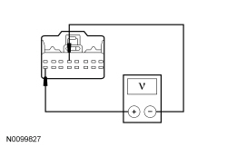 | Yes
GO to E4 . No REPAIR circuit GD116 (BK/VT). REPOWER the SRS . REFER to Section 501-20B . TEST the system for normal operation. |
| E4 CHECK THE CLOCKSPRING FOR AN OPEN | |
  | Yes
GO to E5 . No INSTALL a new clockspring. REFER to Section 501-20B . TEST the system for normal operation. |
| E5 CHECK FOR VOLTAGE TO THE INOPERATIVE STEERING WHEEL ILLUMINATION SOURCE USING THE CONNECTOR GROUND | |
 | Yes
INSTALL a new steering wheel switch. REFER to Section 211-05 . INSTALL the driver airbag module. REFER to Section 501-20B . TEST the system for normal operation. No REPAIR the steering wheel harness. If the steering wheel harness cannot be repaired, INSTALL a new steering wheel. REFER to Section 211-04 . TEST the system for normal operation. |
Pinpoint Test F: One Or More Switch Illumination is Inoperative
Refer to Wiring Diagrams Cell 71 , Cluster and Panel Illumination for schematic and connector information.
When the parking lamps are on, the Smart Junction Box (SJB) sends a pulse-width modulated voltage to the dimmable components.
When the accessory delay relay is energized, voltage is supplied to the door lock control switches and the window control switches.
This pinpoint test is intended to diagnose the following:
NOTICE: Use the correct probe adapter(s) when making measurements. Failure to use the correct probe adapter(s) may damage the connector.
| Test Step | Result / Action to Take | ||||||||||||||||||||||||||||||
|---|---|---|---|---|---|---|---|---|---|---|---|---|---|---|---|---|---|---|---|---|---|---|---|---|---|---|---|---|---|---|---|
| F1 CHECK THE RECORDED RESULTS FROM THE SJB SELF-TEST | |||||||||||||||||||||||||||||||
| Yes
REFER to DTC Charts in this section. No GO to F2 . | ||||||||||||||||||||||||||||||
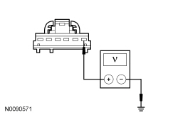
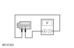
| F2 CHECK THE VOLTAGE TO THE SINGLE ILLUMINATION SOURCE | |||||||||||||||||||||||||||||||
NOTE: If the headlamp switch illumination is the inoperative source, unplug the headlamp switch connector to measure the illumination circuit voltage. Unplugging the connector causes the SJB to turn the exterior lights on by default for 10 minutes, so it is unnecessary to turn on the headlamp switch. NOTE: For a door lock control switch, window control switch or roof opening panel control switch, make sure the door locks, the power windows and roof opening panel operate correctly before continuing diagnostics.
 | Yes
For the convertible top switch, INSTALL a new convertible top switch. REFER to Section 501-18 . TEST the system for normal operation. For a door lock control switch, INSTALL a new door lock switch. REFER to Section 501-14 . TEST the system for normal operation. For a floor shifter, INSTALL a new floor shifter. REFER to Brake Shift Interlock Actuator in Section 307-05 . TEST the system for normal operation. For all other components, GO to F3 . No REPAIR the circuit in question for an open. TEST the system for normal operation. | ||||||||||||||||||||||||||||||
| F3 CHECK THE VOLTAGE TO THE SINGLE ILLUMINATION SOURCE USING THE CONNECTOR GROUND | |||||||||||||||||||||||||||||||
 | Yes
INSTALL a new component in question. TEST the system for normal operation. No REPAIR the ground circuit in question for an open. TEST the system for normal operation. |