
FLU77-4 or equivalent


105-R025D or equivalent
SECTION 413-06: Horn
| 2014 Mustang Workshop Manual
|
DIAGNOSIS AND TESTING
| Procedure revision date: 01/07/2013
|
| Fluke 77-IV Digital Multimeter
FLU77-4 or equivalent |
|
Vehicle Communication Module (VCM) and Integrated Diagnostic System (IDS) software with appropriate hardware, or equivalent scan tool
|
| Flex Probe Kit
105-R025D or equivalent |
Principles of Operation
NOTE: The Smart Junction Box (SJB) is also known as the Generic Electronic Module (GEM).
The SJB supplies the control and switched voltage to the horn relay (integrated into the SJB ). When the driver air bag is pressed, ground is supplied through the clockspring to the horn relay. The horn relay is then energized, directing voltage to the horn and enabling the horn to sound.
The horn switch is comprised of 2 sets of contacts separated by springs. The lower set is connected to ground and the upper set is connected to the horn signal circuit. When the driver air bag module is pressed, it pushes down on the upper set of contacts, collapsing the springs and allowing the contacts to touch. When the contacts touch, it completes the circuit.
The SJB provides ground to the horn relay control side to sound the horn when the vehicle security system is armed, an intrusion is detected, or the panic alarm is activated.
Inspection and Verification
Visual Inspection Chart
| Electrical |
|---|
|
NOTE: Make sure to use the latest scan tool software release.
If the cause is not visually evident, connect the scan tool to the Data Link Connector (DLC).NOTE: The Vehicle Communication Module (VCM) LED prove-out confirms power and ground from the DLC are provided to the VCM .
If the scan tool does not communicate with the VCM :Symptom Chart
| Condition | Possible Sources | Action |
|---|---|---|
|
| |
|
|
Pinpoint Tests
Pinpoint Test A: The Horn Is Inoperative
Refer to Wiring Diagrams Cell 44 , Horn/Cigar Lighter for schematic and connector information.
The Smart Junction Box (SJB) supplies the switched and control voltage to the horn relay (integrated into the SJB ). When the horn switch (part of the steering wheel) is pressed, the switch is grounded to the steering wheel. Ground is then supplied to the horn relay, energizing the horn relay. The horn relay then sends voltage to the horn, enabling the horn to sound.
This pinpoint test is intended to diagnose the following:
NOTICE: Use the correct probe adapter(s) when making measurements. Failure to use the correct probe adapter(s) may damage the connector.
| Test Step | Result / Action to Take |
|---|---|
| A1 CHECK THE SJB OUTPUT | |
| Yes
GO to A2 . No VERIFY the SJB fuse 24 (20A) is OK. If OK, GO to A7 . If not OK, REFER to the Wiring Diagrams Manual to identify the possible causes of circuit short. |
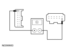
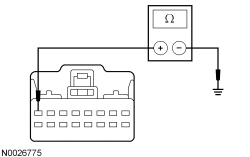
| A2 CHECK THE CLOCKSPRING GROUND CIRCUIT FOR AN OPEN | |
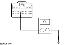 | Yes
GO to A3 . No REPAIR circuit GD116 (BK/VT) for an open. REPOWER the SRS . REFER to Section 501-20B . TEST the system for normal operation. |
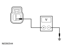
| A3 CHECK FOR VOLTAGE TO THE CLOCKSPRING | |
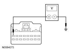 | Yes
GO to A5 . No GO to A4 . |
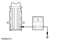
| A4 CHECK THE HORN RELAY COIL GROUND CONTROL CIRCUIT FOR AN OPEN | |
 | Yes
GO to A10 . No REPAIR circuit CRH02 (BU/WH) for an open. REPOWER the SRS . REFER to Section 501-20B . TEST the system for normal operation. |
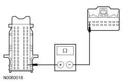
| A5 CHECK THE STEERING WHEEL HARNESS FOR OPENS | |
| Yes
GO to A6 . No REPAIR or INSTALL a new steering wheel harness. INSTALL the driver air bag module. REFER to Section 501-20B . TEST the system for normal operation. |
| A6 CHECK THE CLOCKSPRING FOR AN OPEN | |
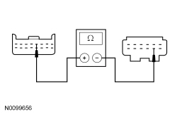  | Yes
INSTALL a new steering wheel. REFER to Section 211-04 . TEST the system for normal operation. No INSTALL a new clockspring. REFER to Section 501-20B . TEST the system for normal operation. |
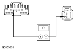
| A7 CHECK FOR VOLTAGE TO THE HORN | |
 | Yes
GO to A8 . No GO to A9 . |
| A8 CHECK FOR VOLTAGE TO THE HORN USING THE CONNECTOR GROUND | |
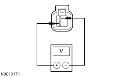 | Yes
INSTALL a new horn. REFER to Horn in this section. TEST the system for normal operation. No REPAIR circuit GD129 (BK/YE) for an open. TEST the system for normal operation. |
| A9 CHECK THE HORN VOLTAGE SUPPLY CIRCUIT FOR AN OPEN | |
 | Yes
GO to A10 . No REPAIR circuit SRH01 (YE/RD) for an open. TEST the system for normal operation. |
| A10 CHECK FOR CORRECT SJB OPERATION | |
| Yes
INSTALL a new SJB . REFER to Section 419-10 . REPOWER the SRS . REFER to Section 501-20B . TEST the system for normal operation. No The system is operating correctly at this time. The concern may have been caused by a loose or corroded connector. REPOWER the SRS . REFER to Section 501-20B . |
Pinpoint Test B: The Horn Is Always On
Refer to Wiring Diagrams Cell 44 , Horn/Cigar Lighter for schematic and connector information.
The Smart Junction Box (SJB) supplies the switched and control voltage to the horn relay (integrated into the SJB ). When the horn switch (part of the steering wheel) is pressed, the switch is grounded to the steering wheel. Ground is then supplied to the horn relay, energizing the horn relay. The horn relay then sends voltage to the horn, enabling the horn to sound.
This pinpoint test is intended to diagnose the following:
NOTICE: Use the correct probe adapter(s) when making measurements. Failure to use the correct probe adapter(s) may damage the connector.
| Test Step | Result / Action to Take |
|---|---|
| B1 CHECK THE HORN POWER SUPPLY CIRCUIT FOR A SHORT TO VOLTAGE | |
| Yes
REPAIR circuit SRH01 (YE/RD) for a short to voltage. TEST the system for normal operation. No GO to B2 . |
| B2 CHECK THE HORN SWITCH INPUT | |
| Yes
GO to B6 . No GO to B3 . |
| B3 CHECK THE HORN RELAY COIL GROUND CONTROLLED CIRCUIT FOR A SHORT TO GROUND | |
 | Yes
GO to B4 . No REPAIR circuit CRH02 (BU/WH) for a short to ground. REPOWER the SRS . REFER to Section 501-20B . TEST the system for normal operation. |
| B4 CHECK THE CLOCKSPRING FOR A SHORT TO GROUND | |
 | Yes
GO to B5 . No INSTALL a new clockspring. REFER to Section 501-20B . TEST the system for normal operation. |
| B5 CHECK THE STEERING WHEEL HARNESS FOR A SHORT | |
| Yes
INSTALL a new steering wheel. REFER to Section 211-04 . TEST the system for normal operation. No REPAIR or INSTALL a new steering wheel harness. INSTALL the driver air bag module. REFER to Section 501-20B . TEST the system for normal operation. |
| B6 CHECK FOR CORRECT SJB OPERATION | |
| Yes
INSTALL a new SJB . REFER to Section 419-10 . TEST the system for normal operation. No The system is operating correctly at this time. The concern may have been caused by a loose or corroded connector. |