
FLU77-4 or equivalent


300-NUD105-R025DE or equivalent
SECTION 413-13: Parking Aid
| 2014 Mustang Workshop Manual
|
DIAGNOSIS AND TESTING
| Procedure revision date: 01/07/2013
|
| Fluke 77-IV Digital Multimeter
FLU77-4 or equivalent |
| Vehicle Communication Module (VCM) and Integrated Diagnostic System (IDS) software with appropriate hardware, or equivalent scan tool
|
| Flex Probe Kit
300-NUD105-R025DE or equivalent |
Principles of Operation
NOTE: The luggage compartment lid must be closed for correct operation of the video camera system.
NOTE: The Smart Junction Box (SJB) is also known as the Generic Electronic Module (GEM).
The rear video camera system is used to assist the driver while reversing or parking the vehicle. For vehicles without navigation, the image of the area behind the vehicle is displayed in the LH side of the auto-dimming interior mirror. For vehicles with navigation, the image of the area behind the vehicle is displayed in the Front Display Interface Module (FDIM). A dashed line on the displayed image represents the center of the vehicle and 3 color-coded lines (red, yellow, green) identify different zones between the rear of the vehicle and objects located behind the vehicle.
NOTE: The color-coded lines may not indicate accurate or consistent distances between objects located behind the vehicle and the rear of the vehicle. This normal condition is due to variances in vehicle ride height, including, but not limited to, vehicle loading. The color coded lines and center line, if available, can appear to be off center or misaligned from the target. This is due to the placement of the video camera being off centered to the rear of the vehicle. The lines are designed to guide the driver to the correct target even if they appeared not centered.
For vehicles without navigation, the signal from the rear video camera is sent to the auto-dimming interior mirror display on a pair of shielded video circuits. For vehicles with navigation, the signal from the rear video camera is sent to the FDIM on a pair of shielded video circuits. The displayed video image is horizontally inverted from that viewed from the video camera perspective to mimic a conventional mirror image. The rear video camera system is active with the ignition in RUN and the transmission selector in the REVERSE (R) position.
For vehicles without navigation, the system remains active for approximately 3 seconds after the transmission selector is moved from the REVERSE (R) position. The rear video camera system cannot be disabled during these conditions.
For vehicles with navigation, the video system has a delay feature that keeps the image displayed on the FDIM until the vehicle reaches 8 km/h (5 mph) and the vehicle is shifted out of REVERSE (R). The operator has the ability to turn the delay feature on or off with the on screen options in the FDIM . The image is not displayed if the vehicle is shifted into PARK (P).
Inspection and Verification
Visual Inspection Chart
| Mechanical | Electrical |
|---|---|
|
|
NOTE: Make sure to use the latest scan tool software release.
If the cause is not visually evident, connect the scan tool to the Data Link Connector (DLC).NOTE: The Vehicle Communication Module (VCM) LED prove-out confirms power and ground from the DLC are provided to the VCM .
If the scan tool still does not communicate with the VCM :DTC Charts
Audio Control Module (ACM) DTC Chart
NOTE: This module utilizes a 5-character DTC followed by a 2-character failure-type code. The failure-type code provides information about specific fault conditions such as opens, or shorts to ground. Continuous memory DTCs have an additional 2-character DTC status code suffix to assist in determining DTC history.
| DTC | Description | Action |
|---|---|---|
| C1001:01 | Vision System Camera: General Electrical Failure | GO to Pinpoint Test G . |
| All other DTCs | — | REFER to the Diagnostic Trouble Code (DTC) Charts in Section 415-00 |
Symptom Chart
| Condition | Possible Sources | Action |
|---|---|---|
|
| |
|
| |
|
| |
|
| |
|
| |
|
| |
|
|
Pinpoint Tests
Pinpoint Test G: The Rear Video Is Inoperative
Refer to Wiring Diagrams Cell 131 , Parking Aid for schematic and connector information.
For vehicles without navigation, with the gear selector in the REVERSE (R) position, a reverse voltage signal is sent to the auto-dimming interior mirror supplying power to the display in the mirror. The video camera signal is sent to the auto-dimming interior mirror. The video signal from the video camera displays an image on the LH side of the auto-dimming interior mirror.
For vehicles with navigation, with the gear selector in the REVERSE (R) position, a reverse signal is sent from the Instrument Panel Cluster (IPC) to the Audio Control Module (ACM) over the Medium Speed Controller Area Network (MS-CAN), enabling the system. The video signal from the video camera displays an image on the Front Display Interface Module (FDIM).
This pinpoint test is intended to diagnose the following:
NOTICE: Use the correct probe adapter(s) when making measurements. Failure to use the correct probe adapter(s) may damage the connector.
NOTE: Failure to disconnect the battery when instructed will result in false resistance readings. Refer to Section 414-01 .
| Test Step | Result / Action to Take |
|---|---|
| G1 CHECK AND CLEAN THE REAR VIDEO CAMERA LENS | |
| Yes
Vehicles equipped with navigation, GO to G8 . Vehicles equipped without navigation, GO to G2 . No The system is operating correctly at this time. The concern was caused by a dirty camera lens. |
| G2 CHECK THE REVERSING LAMPS OPERATION | |
| Yes
GO to G3 . No REFER to Section 417-01 . |
| G3 CHECK FOR A VIDEO CAMERA SIGNAL | |
| Yes
The auto-dimming interior mirror is functional. There is no signal from the video camera. GO to G10 . No GO to G4 . |
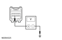
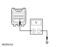
| G4 CHECK THE AUTO-DIMMING INTERIOR MIRROR VOLTAGE SUPPLY CIRCUIT FOR AN OPEN | |
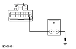 | Yes
GO to G5 . No VERIFY the Smart Junction Box (SJB) fuse 41 (15A) is OK. If OK, REPAIR the circuit. If not OK, REFER to the Wiring Diagrams Manual to identify the possible causes of the circuit short. TEST the system for normal operation. |
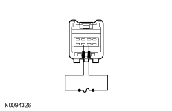
| G5 CHECK THE AUTO-DIMMING INTERIOR MIRROR REVERSE INPUT CIRCUIT | |
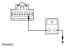 | Yes
GO to G7 . No GO to G6 . |
| G6 CHECK THE AUTO-DIMMING INTERIOR MIRROR REVERSE INPUT CIRCUIT FOR AN OPEN | |
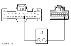 | Yes
GO to G19 . No REPAIR the circuit. TEST the system for normal operation. |
| G7 CHECK THE AUTO-DIMMING INTERIOR MIRROR GROUND CIRCUIT FOR AN OPEN | |
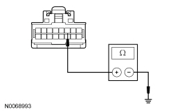 | Yes
INSTALL a new auto-dimming interior mirror. REFER to Section 501-09 . TEST the system for normal operation. No REPAIR the circuit. TEST the system for normal operation. |
| G8 VERIFY THE REVERSE SIGNAL INPUT | |
| Yes
GO to G9 . No REFER to Section 307-01 to diagnose the PRNDL. |
| G9 CHECK THE FDIM DISPLAY | |
| Yes
The FDIM display is functional. There is no signal from the video camera. GO to G10 . No INSTALL a new FDIM . REFER to Section 415-00 . TEST the system for normal operation. |
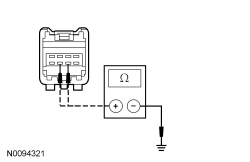
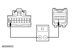
| G10 CHECK THE VIDEO SIGNAL CIRCUITS INTEGRITY | |
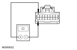  | Yes
REMOVE the jumper wire. GO to G11 . No REMOVE the jumper wire. GO to G13 . |
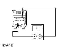
| G11 CHECK THE VIDEO CAMERA VOLTAGE SUPPLY CIRCUIT FOR AN OPEN | |
 | Yes
GO to G12 . No VERIFY that the SJB fuse 29 (5A) is OK. If OK, REPAIR the circuit. If not OK, REFER to the Wiring Diagrams Manual to identify the possible causes of the circuit short. |
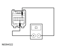
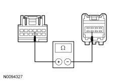
| G12 CHECK THE VIDEO CAMERA GROUND CIRCUIT FOR AN OPEN | |
 | Yes
GO to G18 . No REPAIR the circuit. TEST the system for normal operation. |
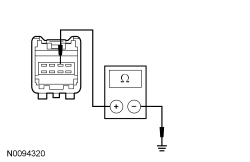
| G13 CHECK THE VIDEO CAMERA VIDEO SIGNAL CIRCUITS FOR A SHORT TO GROUND | |
 | Yes
GO to G14 . No REPAIR the circuit in question. TEST the system for normal operation. |
| G14 CHECK THE VIDEO CAMERA VIDEO SIGNAL CIRCUITS FOR A SHORT TO VIDEO SHIELD | |
  | Yes
GO to G15 . No REPAIR the circuit in question. TEST the system for normal operation. |
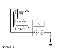
| G15 CHECK THE VIDEO CAMERA VIDEO SIGNAL CIRCUITS FOR A SHORT TO VOLTAGE | |
  | Yes
REPAIR the circuit in question. TEST the system for normal operation. No GO to G16 . |
| G16 CHECK VIDEO SIGNAL CIRCUITS FOR AN OPEN | |
 | Yes
REMOVE the jumper wire. GO to G18 . No REMOVE the jumper wire. GO to G17 . |
| G17 CHECK VIDEO SIGNAL CIRCUIT (+) FOR AN OPEN | |
  | Yes
REPAIR circuit RMP19 (BN/VT). TEST the system for normal operation. No REPAIR circuit VMP19 (WH/GN). TEST the system for normal operation. |
| G18 CHECK FOR CORRECT VIDEO CAMERA OPERATION | |
| Yes
INSTALL a new video camera. REFER to Video Camera in this section. TEST the system for normal operation. No The system is operating correctly at this time. The concern may have been caused by a loose or corroded connector. |
| G19 CHECK FOR CORRECT BCM-B OPERATION | |
| Yes
INSTALL a new BCM-B . REFER to Section 419-10 . TEST the system for normal operation. No The system is operating correctly at this time. The concern may have been caused by a loose or corroded connector. CLEAR the DTCs. REPEAT the self-test. |
Pinpoint Test H: Poor Image Quality
Refer to Wiring Diagrams Cell 131 , Parking Aid for schematic and connector information.
For vehicles without navigation, with the gear selector in the REVERSE (R) position, a reverse voltage signal is sent to the auto-dimming interior mirror supplying power to the display in the mirror. The video camera signal is sent to the auto-dimming interior mirror. A pair of shielded wires carries the video signal from the video camera and displays an image on the LH side of the auto-dimming interior mirror.
For vehicles with navigation, with the gear selector in the REVERSE (R) position, a reverse signal is sent from the Instrument Panel Cluster (IPC) to the Audio Control Module (ACM) over the Medium Speed Controller Area Network (MS-CAN), enabling the system. A pair of shielded wires carries the video signal from the video camera and displays an image on the Front Display Interface Module (FDIM).
This pinpoint test is intended to diagnose the following:
NOTICE: Use the correct probe adapter(s) when making measurements. Failure to use the correct probe adapter(s) may damage the connector.
NOTE: Failure to disconnect the battery when instructed will result in false resistance readings. Refer to Section 414-01 .
| Test Step | Result / Action to Take |
|---|---|
| H1 CHECK AND CLEAN THE REAR VIDEO CAMERA LENS | |
| Yes
GO to H2 . No The system is operating correctly at this time. The concern was caused by a dirty video camera lens. |
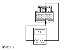
| H2 CHECK THE VIDEO SIGNAL CIRCUITS INTEGRITY | |
| Yes
REMOVE the jumper wire. GO to H8 . No REMOVE the jumper wire. GO to H3 . |
| H3 CHECK THE VIDEO CAMERA GROUND CIRCUIT FOR AN OPEN | |
| Yes
GO to H4 . No REPAIR the circuit. TEST the system for normal operation. |
| H4 CHECK THE VIDEO CAMERA VIDEO SIGNAL CIRCUITS FOR A SHORT TO GROUND | |
| Yes
GO to H5 . No REPAIR the circuit in question. TEST the system for normal operation. |
| H5 CHECK THE VIDEO CAMERA VIDEO SIGNAL CIRCUITS FOR A SHORT TO VIDEO SHIELD | |
| Yes
GO to H6 . No REPAIR the circuit in question. TEST the system for normal operation. |
| H6 CHECK VIDEO SIGNAL CIRCUITS FOR AN OPEN | |
| Yes
REMOVE the jumper wire. GO to H8 . No REMOVE the jumper wire. GO to H7 . |
| H7 CHECK VIDEO SIGNAL CIRCUIT (+) FOR AN OPEN | |
| Yes
REPAIR circuit RMP19 (BN/VT). TEST the system for normal operation. No REPAIR circuit VMP19 (WH/GN). TEST the system for normal operation. |
| H8 CHECK FOR CORRECT VIDEO CAMERA OPERATION | |
| Yes
INSTALL a new video camera. REFER to Video Camera in this section. TEST the system for normal operation. No The system is operating correctly at this time. The concern may have been caused by a loose or corroded connector. |
Pinpoint Test I: The Rear Video Mirror Display Is Always On (Vehicles Without Navigation)
The video camera receives a supply voltage with the ignition switch in the RUN position. When the gear selector is in the REVERSE (R) position, a reverse voltage signal is sent to the auto-dimming interior mirror supplying power to the display in the mirror. The video camera signal is sent to the auto-dimming interior mirror. The video signal from the video camera displays an image on the LH side of the auto-dimming interior mirror.
This pinpoint test is intended to diagnose the following:
| Test Step | Result / Action to Take |
|---|---|
| I1 CHECK THE REVERSING LAMPS OPERATION | |
| Yes
GO to I2 . No REFER to Section 417-01 . |
| I2 CHECK FOR CORRECT AUTO-DIMMING INTERIOR MIRROR OPERATION | |
| Yes
INSTALL a new auto-dimming interior mirror. REFER to Section 501-09 . TEST the system for normal operation. No The system is operating correctly at this time. The concern may have been caused by a loose or corroded connector. |