
FLU77-4 or equivalent


NUD105-R025D or equivalent
SECTION 419-01A: Anti-Theft — Perimeter
| 2014 Mustang Workshop Manual
|
DIAGNOSIS AND TESTING
| Procedure revision date: 01/07/2013
|
| Fluke 77-IV Digital Multimeter
FLU77-4 or equivalent |
| Vehicle Communication Module (VCM) and Integrated Diagnostic System (IDS) software with appropriate hardware, or equivalent scan tool
|
| Flex Probe Kit
NUD105-R025D or equivalent |
Principles of Operation
NOTE: The Smart Junction Box (SJB) is also known as the Generic Electronic Module (GEM).
When the perimeter alarm is armed, the SJB monitors the door ajar switches, the hood switch, the luggage compartment lid ajar switch, and the Body Control Module B (BCM-B) sends a message over the local interconnect network to arm the intrusion and inclination sensor.
If any intrusion is detected without the alarm being deactivated, the SJB activates the perimeter alarm and sounds the horn and flashes the turn signals in regular intervals.
The system arms when:
If the doors are locked using the manual push buttons, no part of the perimeter alarm is armed. The SJB monitors the status of all entry points. If any entry point is open, the alarm arms everything except for the open entry point. The SJB adds the entry point to the protected status when the closure of the open entry point is detected. Note that only when the system is armed by locking the door using the key in the door lock cylinder is there no intrusion/inclination protection. Arming the system (locking the doors) using the RKE transmitter or using the door lock control switch allows the intrusion/inclination protection to also arm.
NOTE: The intrusion sensing feature is not activated if either door or the convertible top (if equipped) is open when the vehicle is armed.
The SJB inhibits the intrusion and inclination sensor and the luggage compartment lid ajar inputs if the luggage compartment lid is opened with the RKE transmitter . Once the luggage compartment lid is closed, the intrusion and inclination sensor and the luggage compartment lid ajar switch are monitored by the SJB .
Perimeter Alarm Arming
The system can be armed using any of the following methods:
Perimeter Alarm Disarming
The system can be disarmed using any of the following methods (these steps also deactivate an activated alarm):
Perimeter Alarm Deactivation
To deactivate an activated alarm (this step will not disarm the alarm), press the PANIC button on the RKE transmitter.
Alarm Event PIDs
The SJB has PIDs available that show what caused the last alarm events. The 4 SJB alarm event PIDs are AL_EVT1 through 4. The cause for the most recent alarm activation is always listed in the first alarm event PID. These PIDs display what caused the alarm to activate and can be a very useful tool when trying to identify the cause of a false alarm activation.
Inspection and Verification
Visual Inspection Chart
| Mechanical | Electrical |
|---|---|
|
|
NOTE: Make sure to use the latest scan tool software release.
If the cause is not visually evident, connect the scan tool to the Data Link Connector (DLC).NOTE: The Vehicle Communication Module (VCM) LED prove-out confirms power and ground from the DLC are provided to the VCM .
If the scan tool does not communicate with the VCM :DTC Charts
Body Control Module B (BCM-B) DTC Chart
NOTE: This module utilizes a 5-character DTC followed by a 2-character failure-type code. The failure-type code provides information about specific fault conditions such as opens, or shorts to ground. Continuous memory DTCs have an additional 2-character DTC status code suffix to assist in determining DTC history.
| DTC | Description | Action |
|---|---|---|
| B109F:08 | Intrusion Sensor Module: Bus Signal / Message Failures | GO to Pinpoint Test E . |
| B109F:49 | Intrusion Sensor Module: Internal Electronic Failure | INSTALL a new intrusion and inclination sensor. REFER to Intrusion and Inclination Sensor in this section. TEST the system for normal operation. |
| B109F:55 | Intrusion Sensor Module: Not Configured | REFER to Section 418-01 . |
| B109F:97 | Intrusion Sensor Module: Component Or System Operation Obstructed Or Blocked | NOTE: The Body Control Module B (BCM-B) DTC B109F:97 is a continuous memory and on-demand DTC that sets when there are 3 successive failures of the intrusion and inclination sensor module to arm and there is no indication of a module fault and the communication link between the module and the BCM-B appears to have sufficient integrity. CHECK for any blockages/restrictions near the intrusion and inclination sensor that may hinder/affect the operation of the sensor. |
| All other DTCs | — | REFER to the Diagnostic Trouble Code (DTC) Chart in Section 419-10 . |
Smart Junction Box (SJB) DTC Chart
| DTC | Description | Action |
|---|---|---|
| B1520 | Hood Switch Circuit Open | GO to Pinpoint Test C . |
| B2100 | Door Driver Key Cylinder Switch Failure | GO to Pinpoint Test A . |
| All other DTCs | — | REFER to the Diagnostic Trouble Code (DTC) Chart in Section 419-10 . |
Symptom Chart
| Condition | Possible Sources | Action |
|---|---|---|
|
|
|
|
|
|
|
| |
|
| |
|
| |
|
| |
|
|
|
|
|
|
|
|
|
Pinpoint Tests
Pinpoint Test A: The Alarm System Does Not Arm/Disarm From The Driver Door Lock Cylinder
Refer to Wiring Diagrams Cell 117 , Remote Keyless Entry and Alarm for schematic and connector information.
NOTE: The intrusion and inclination protection features cannot be activated when locking the vehicle with the door lock cylinder. This allows raising the vehicle on a hoist, transporting or towing the vehicle, or when authorized motion inside the vehicle is likely.
The Smart Junction Box (SJB) monitors the driver door lock through the set/reset switch (part of the driver door latch) and the set and reset input circuits. When a key in the door lock cylinder is turned to the lock position it grounds the set circuit signalling the SJB to arm the alarm. When a key in the door lock cylinder is turned to the unlock position it grounds the reset circuit signalling the SJB to disarm the alarm. The driver door latch has a dedicated ground circuit that is used for the door ajar and set/reset switches.
This pinpoint test is intended to diagnose the following:
NOTICE: Use the correct probe adapter(s) when making measurements. Failure to use the correct probe adapter(s) may damage the connector.
| Test Step | Result / Action to Take | |||||||||
|---|---|---|---|---|---|---|---|---|---|---|
| A1 CHECK THE RECORDED SJB DTCs FROM THE SELF-TEST | ||||||||||
| Yes
GO to A2 . No GO to A4 . | |||||||||
| A2 CHECK THE DRIVER DOOR LATCH FOR A SHORT TO GROUND | ||||||||||
| Yes
GO to A3 . No INSTALL a new driver door latch. REFER to Section 501-14 . TEST the system for normal operation. | |||||||||
| A3 CHECK THE SET/RESET CIRCUITS FOR A SHORT TO GROUND | ||||||||||
 | Yes
GO to A7 . No REPAIR the circuit in question for a short to ground. CLEAR the DTCs. TEST the system for normal operation. | |||||||||
| A4 CHECK THE COURTESY LAMP OPERATION | ||||||||||
| Yes
GO to A5 . No REFER to Section 417-02 to diagnose the driver door ajar input concern. | |||||||||
| A5 CHECK THE DRIVER DOOR LATCH | ||||||||||
 | Yes
INSTALL a new driver door latch. REFER to Section 501-14 . TEST the system for normal operation. No GO to A6 . | |||||||||
| A6 CHECK THE SET/RESET CIRCUITS FOR AN OPEN | ||||||||||
 | Yes
GO to A7 . No REPAIR the circuit in question for an open. TEST the system for normal operation. | |||||||||
| A7 CHECK FOR CORRECT SJB OPERATION | ||||||||||
| Yes
INSTALL a new SJB . REFER to Section 419-10 . TEST the system for normal operation. No The system is operating correctly at this time. The concern may have been caused by a loose or corroded connector. |
Pinpoint Test B: The Alarm System Does Not Activate From An Unauthorized Entry At The Hood
Refer to Wiring Diagrams Cell 117 , Remote Keyless Entry and Alarm for schematic and connector information.
When the alarm system is armed, the Smart Junction Box (SJB) monitors the hood ajar switch. If the hood is opened while the alarm is armed, the hood ajar switch removes ground from the signal circuit. This signals the SJB that an unauthorized intrusion to the engine compartment has occurred and the SJB activates the alarm.
This pinpoint test is intended to diagnose the following:
NOTICE: Use the correct probe adapter(s) when making measurements. Failure to use the correct probe adapter(s) may damage the connector.
| Test Step | Result / Action to Take |
|---|---|
| B1 RETRIEVE THE RECORDED DTCs IN THE SJB | |
NOTE: DTC B1520 sets if the hood is open. Make sure the hood is closed prior to running the self-test. | Yes
GO to Pinpoint Test C . No GO to B2 . |
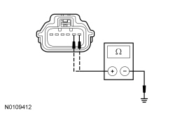
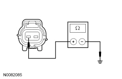
| B2 CHECK THE HOOD SWITCH | |
| Yes
INSTALL a new hood switch. TEST the system for normal operation. No GO to B3 . |
| B3 CHECK THE HOOD SWITCH SENSE CIRCUIT FOR A SHORT TO GROUND | |
 | Yes
GO to B4 . No REPAIR the circuit. TEST the system for normal operation. |
| B4 CHECK FOR CORRECT SJB OPERATION | |
| Yes
INSTALL a new SJB . REFER to Section 419-10 . TEST the system for normal operation. No The system is operating correctly at this time. The concern may have been caused by a loose or corroded connector. |
Pinpoint Test C: DTC B1520
Refer to Wiring Diagrams Cell 117 , Remote Keyless Entry and Alarm for schematic and connector information.
When the alarm system is armed, the Smart Junction Box (SJB) monitors the hood ajar switch. If the hood is opened while the alarm is armed, the hood ajar switch removes ground from the signal circuit. This signals the SJB that an unauthorized intrusion to the engine compartment has occurred and the SJB activates the perimeter alarm.
This pinpoint test is intended to diagnose the following:
NOTICE: Use the correct probe adapter(s) when making measurements. Failure to use the correct probe adapter(s) may damage the connector.
| Test Step | Result / Action to Take |
|---|---|
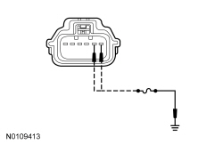
| C1 CHECK THE HOOD SWITCH | |
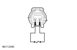 | Yes
REMOVE the jumper wire. GO to C2 . No REMOVE the jumper wire. INSTALL a new hood switch. TEST the system for normal operation. |
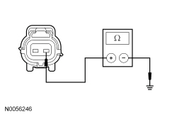
| C2 CHECK THE HOOD SWITCH GROUND CIRCUIT FOR AN OPEN | |
 | Yes
GO to C3 . No REPAIR the circuit. CLEAR the DTCs. REPEAT the self-test. |
| C3 CHECK THE HOOD SWITCH SENSE CIRCUIT FOR AN OPEN | |
 | Yes
GO to C4 . No REPAIR the circuit. CLEAR the DTCs. REPEAT the self-test. |
| C4 CHECK FOR CORRECT SJB OPERATION | |
| Yes
INSTALL a new SJB . REFER to Section 419-10 . REPEAT the self-test. TEST the system for normal operation. No The system is operating correctly at this time. The concern may have been caused by a loose or corroded connector. |
Pinpoint Test D: The Alarm System Does Not Arm/No Turn Signal Flash Confirmation
The Smart Junction Box (SJB) controls the perimeter alarm system and based on inputs either arms, disarms or activates the alarm. When the alarm is activated, the SJB sounds the horn and flashes the turn signals in regular intervals. The SJB receives inputs for the door lock status, hood ajar, door ajar, luggage compartment lid ajar and the intrusion and inclination sensor. The SJB also receives signals from the Remote Keyless Entry (RKE) transmitters.
For the perimeter alarm to arm and provide a flash of the turn signals, the following conditions must be met:
Once all the conditions are met, the alarm system enters a pre-arm phase and begins a 20-second countdown. After 20 seconds have passed and no unlock command is received or any hood or door is opened, the perimeter alarm arms.
The perimeter alarm is activated when:
This pinpoint test is intended to diagnose the following:
| Test Step | Result / Action to Take |
|---|---|
| D1 RETRIEVE THE RECORDED DTCs IN THE SJB AND BCM-B | |
| Yes
REFER to DTC Charts in this section. No GO to D2 . |
| D2 CHECK THE COURTESY LAMP OPERATION | |
| Yes
GO to D3 . No REFER to Section 417-02 to diagnose the door ajar inputs. |
| D3 CHECK THE LUGGAGE COMPARTMENT LAMP OPERATION | |
| Yes
GO to D4 . No REFER to Section 417-02 to diagnose the luggage compartment lid ajar input. |
| D4 VERIFY THE HAZARD LAMP OPERATION | |
| Yes
GO to D5 . No REFER to Section 417-01 to diagnose the hazard lamps. |
| D5 CHECK THE RKE TRANSMITTER FUNCTION | |
| Yes
GO to D6 . No REFER to Section 501-14 to diagnose the RKE function. |
| D6 CHECK FOR CORRECT SJB OPERATION | |
| Yes
INSTALL a new SJB . REFER to Section 419-10 . TEST the system for normal operation. No The system is operating correctly at this time. The concern may have been caused by a loose or corroded connector. |
Pinpoint Test E: The Alarm System Does Not Operate Correctly — Intrusion and Inclination Sensing
Refer to Wiring Diagrams Cell 117 , Remote Keyless Entry and Alarm for schematic and connector information.
NOTE: All the windows must be closed for correct intrusion sensing operation.
NOTE: The inclination sensing feature must be disarmed before raising the vehicle on a hoist to prevent false alarms.
Arming the perimeter alarm (anti-theft) system by using the key in the door lock cylinder inhibits the intrusion and inclination sensing features. The intrusion and inclination sensing features can be activated by using the Remote Keyless Entry (RKE) transmitter or the door lock control switch to lock the vehicle and arm the perimeter alarm system. The convertible top (if equipped), the luggage compartment lid, and all the doors must be closed for the intrusion sensing feature to activate. The intrusion and inclination sensor receives voltage at all times and has a dedicated ground circuit. When the sensor senses a change in motion or in inclination, the change is communicated to the Body Control Module B (BCM-B) through the local interconnect network. The BCM-B sends a message over the Medium Speed Controller Area Network (MS-CAN) to the Smart Junction Box (SJB). The SJB then activates the perimeter alarm.
This pinpoint test is intended to diagnose the following:
NOTICE: Use the correct probe adapter(s) when making measurements. Failure to use the correct probe adapter(s) may damage the connector.
| Test Step | Result / Action to Take |
|---|---|
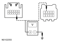
| E1 CHECK THE INTRUSION AND INCLINATION SENSOR POWER CIRCUIT FOR VOLTAGE | |
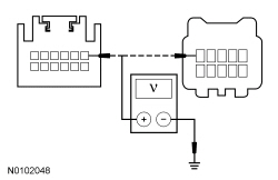 | Yes
GO to E2 . No VERIFY the SJB fuse 11 (10A) is OK. If OK, REPAIR the circuit for an open. If not OK, REFER to the Wiring Diagrams Manual to identify the possible causes of the circuit short. CLEAR the DTCs. REPEAT the self-test. |
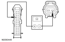
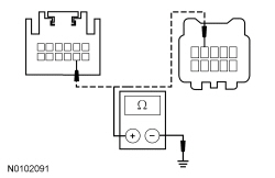
| E2 CHECK THE INTRUSION AND INCLINATION SENSOR GROUND CIRCUIT FOR AN OPEN | |
 | Yes
GO to E3 . No REPAIR the circuit. CLEAR the DTCs. REPEAT the self-test. |
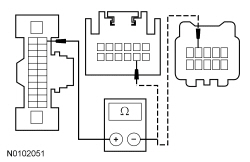
| E3 CHECK THE LOCAL INTERCONNECT NETWORK COMMUNICATION LINK FOR A SHORT TO VOLTAGE | |
 | Yes
REPAIR the circuit. CLEAR the DTCs. REPEAT the self-test. No GO to E4 . |
| E4 CHECK THE LOCAL INTERCONNECT NETWORK COMMUNICATION LINK FOR A SHORT TO GROUND | |
 | Yes
GO to E5 . No REPAIR the circuit. CLEAR the DTCs. REPEAT the self-test. |
| E5 CHECK THE LOCAL INTERCONNECT NETWORK COMMUNICATION LINK FOR AN OPEN | |
 | Yes
INSTALL a new intrusion and inclination sensor. REFER to Intrusion and Inclination Sensor in this section. CLEAR the DTCs. REPEAT the self-test. IF the concern is still present, GO to E6 . No REPAIR the circuit. CLEAR the DTCs. REPEAT the self-test. |
| E6 CHECK FOR CORRECT BCM-B OPERATION | |
| Yes
INSTALL a new BCM-B . REFER to Section 419-10 . TEST the system for normal operation. No The system is operating correctly at this time. The concern may have been caused by a loose or corroded connector. |