
FLU77-4 or equivalent


105-R025D or equivalent
SECTION 419-01B: Anti-Theft — Passive Anti-Theft System (PATS)
| 2014 Mustang Workshop Manual
|
DIAGNOSIS AND TESTING
| Procedure revision date: 01/07/2013
|
| Fluke 77-IV Digital Multimeter
FLU77-4 or equivalent |
|
Vehicle Communication Module (VCM) and Integrated Diagnostic System (IDS) software with appropriate hardware, or equivalent scan tool
|
| Flex Probe Kit
105-R025D or equivalent |
Principles of Operation
NOTE: Replacement of the Passive Anti-Theft System (PATS) transceiver does not require the PATS keys to be programmed into the Instrument Panel Cluster (IPC) again.
NOTE: When using the Integrated Diagnostic System (IDS), the IPC and the PCM parameters are reset at the same time.
NOTE: Make sure any aftermarket remote start systems have been removed from the vehicle before any PATS -related no-start concerns are investigated.
NOTE: A minimum of 2 PATS keys must be programmed into the IPC before the vehicle starts.
NOTE: If the IPC or the PCM is being replaced (or both), the parameters must be reset in both modules or the vehicle experiences a PATS no-start. Refer to Passive Anti-Theft System (PATS) Parameter Reset in this section.
NOTE: The Smart Junction Box (SJB) is also known as the Generic Electronic Module (GEM).
Anti-Theft Indicator
PATS uses a visual anti-theft indicator located in the IPC . The anti-theft indicator proves out for 3 seconds when the ignition key is in the ON or START position. If there is a PATS concern, the anti-theft indicator either flashes rapidly or glows steadily when the ignition key is turned to the ON or START position. PATS also flashes the anti-theft indicator every 2 seconds when the ignition key is in the OFF position to act as a visual theft deterrent. Refer to Section 413-01 for information on the anti-theft indicator.
PATS is active only for a few seconds when the vehicle is starting. It is not a PATS concern if the vehicle stalls after it has been running for a minimum of 3 seconds. PATS cannot disable a running vehicle.
A PATS no-start can involve a vehicle no-start due to either the fuel injectors or the starter not operating (or both). If the PATS anti-theft indicator does not prove out and one (or both) of the previous conditions are present, it can be due to a PATS concern. If the anti-theft indicator proves out, and the vehicle does not start, it is probably not a PATS concern. Refer to the Powertrain Control/Emissions Diagnosis (PC/ED) manual. If the anti-theft indicator does not illuminate at all, it can be an IPC concern. GO to Symptom Chart in this section. A low battery voltage condition can cause the PATS to allow starter operation, but can keep the fuel injectors from operating.
Passive Anti-Theft System (PATS) Keys
NOTE: A maximum of 8 PATS keys can be programmed into the IPC .
PATS uses a special ignition key, called an Integrated Keyhead Transmitter (IKT) key that is larger than a conventional ignition key. It contains a permanently installed electronic device called a transponder and also has the Remote Keyless Entry (RKE) transmitter integrated into the keyhead. Each transponder contains a unique encrypted identification code which is one of a very large number of combinations. The addition of this transponder to the key makes it an "encoded" key. The PATS key does not require batteries and should last the lifetime of the vehicle. The transmitter portion of the IKT key has a battery. Each PATS key must be programmed into the IPC before it can be used to start the vehicle. A maximum of 4 IKT keys can be programmed to start the vehicle and operate the RKE functions. If more than 4 IKT keys are programmed, the RKE portion of the additional IKT keys does not operate. The SJB sets DTC B1138 (Memory Full) and the IPC sets DTC B1218:44 if there is an attempt to program 4 or more IKT keys. These additional keys (more than 4 IKT keys) start the vehicle, but cannot operate the RKE system. If additional PATS keys are desired (more than 4, up to 8 total, IKT and PATS ), a standard PATS key (a non- IKT key) can be used. There are special procedures described in this section that must be carried out if a new PATS key is necessary. Refer to Integrated Keyhead Transmitter (IKT) Key Programming Using Diagnostic Equipment or Key Programming Using Two Programmed Keys in this section.
Passive Anti-Theft System (PATS) Transceiver
The PATS transceiver is located in the steering column and communicates with the encoded ignition key. During each vehicle start sequence, the PATS transceiver reads the encoded ignition key identification code and sends data to the IPC . The IPC validates the code, and if it is correct, sends a message to the PCM to ground the starter relay solenoid coil and to allow the fuel injectors to operate.
Passive Anti-Theft System (PATS) Operation
The PATS function is controlled by the IPC . With this type of PATS , there are parameters that need to be reset if either the IPC or the PCM (or both) are replaced. Refer to Passive Anti-Theft System (PATS) Parameter Reset in this section.
When the PATS key is turned to the ON or START position, the IPC initiates the key interrogation sequence by sending a voltage signal to the PATS transceiver. The transceiver then uses its antenna to bounce a signal off the transponder in the PATS key. This process "reads" the PATS key identification code and sends the key identification code back to the IPC , which interprets it and determines if it matches one of the stored key codes. If it does match one of the stored key codes, the IPC sends a message to the PCM to ground the starter relay solenoid coil and to allow the fuel injectors to operate. If it does not match one of the stored key codes, or it is only a partial key read or no key read, the IPC sends a message to the PCM to not ground the starter relay solenoid coil and not allow fuel injector operation. The anti-theft indicator in the IPC flashes (or may glow steadily) and the IPC stores one or more DTCs.
All elements of PATS must be functional before the vehicle starts. If any of the components are not working correctly, the vehicle cannot start.
If the IPC must be replaced for any reason ( PATS or IPC concerns), the PATS keys must also be programmed into the new IPC . Refer to Integrated Keyhead Transmitter (IKT) Key Programming Using Diagnostic Equipment in this section.
PATS disables the vehicle from starting if there is:
Passive Anti-Theft System (PATS) PIDs
Monitoring the IPC PATS PIDs can be very useful in determining which diagnostic steps to follow. Viewing the MASTERKEY PID (verifies if the key is programmed) (with both keys) determines if the key is a programmed key and proves-out the transceiver, circuitry and the IPC . A master key is any key that is programmed into the IPC . Viewing the MIN_KEYS PID (minimum number of keys) (this PID does not change) indicates the minimum number of keys that must be programmed into the IPC in order for the vehicle to start. There must be at least 2 keys programmed into the IPC in this type of PATS before the vehicle starts. Viewing the N_KEYCODE PID (number of keys registered in module) determines if the minimum number of keys has been programmed into the IPC . If the N_KEYCODE PID reads 0 or 1, additional key(s) need to be programmed into the IPC in order to meet the minimum of 2 keys. If the N_KEYCODE PID reads 0 or 1, and the MASTERKEY PID reads Not Present, that particular key must be programmed into the IPC . If the N_KEYCODE PID reads 1, and the MASTERKEY PID reads Present, that particular key is already programmed into the IPC . The SPAREKEY (spare key) PID is defaulted to ENABLE.
When the parameters in the IPC are reset, it clears (erases) the PCM ID from the IPC . A PCM parameter reset causes the PCM to send a PCM ID to the IPC that is necessary for the system to operate. Make sure to cycle the key at least once, then turn the key ON and make an attempt to start the vehicle for 3-5 seconds before attempting more procedures. If only a PCM parameter reset occurs, the ID stored in the IPC does not match the ID being sent by the PCM, and can cause a PATS -related no-start. Carry out the parameter reset, and do not cycle the key until after the parameter reset selection has been highlighted, and the on-screen instructions have been followed. The IDS resets the parameters in both the IPC and the PCM at the same time.
If the PCM_ID reads Stored, the IPC has a PCM ID stored. If it reads Not Stored, a parameter reset may resolve this concern. If the PCM_VFY PID (PCM verify) reads No, the N_KEYCODE PID reads 2 or more and the MASTERKEY PID reads Present, the IPC , and the PCM need to have their parameters reset. Refer to Passive Anti-Theft System (PATS) Parameter Reset in this section.
If the PCM_VFY PID reads NO, the N_KEYCODE PID reads 1 and the MASTERKEY PID reads Present, or if the N_KEYCODE PID reads 0 and the MASTERKEY PID reads Not Present, a minimum of 2 keys need to be programmed into the IPC . Refer to Integrated Keyhead Transmitter (IKT) Key Programming Using Diagnostic Equipment in this section.
The SPAREKEY PID is defaulted to ENABLE. With the SPAREKEY PID displaying ENABLE, the IPC accepts more than 2 keys (up to a maximum of 8) being programmed into the IPC using the Key Programming Using Two Programmed Keys procedure in this section. The SPAREKEY PID can be toggled to DISABLE if the customer wants to disable the customer spare key programming function. To enable or disable the spare key feature, refer to Key Programming Switch State Control in this section. This switch state control does not affect the IKT Key Programming Using Diagnostic Equipment procedure.
In summary, for the PATS PIDs and their correct state in order for the vehicle to start:
Unlimited Key Mode
This system contains a feature named unlimited key mode that has an UNL_KEY_MODE PID (unlimited key mode). This feature allows a customer to program more than 8 keys to their vehicle if they request it. Each vehicle in unlimited key mode is set up with a special unlimited transponder security key code. This allows all the customer vehicles to share the same mechanically cut keys, but no other keys from outside can be used to operate the vehicles. For an individual customer, any randomly selected security key that has been previously mechanically cut and electronically programmed to the vehicle is acceptable. Refer to Spare Key Programming — Unlimited Key Mode in this section.
Inspection and Verification
Visual Inspection Chart
| Mechanical | Electrical |
|---|---|
|
|
NOTE: Make sure to use the latest scan tool software release.
If the cause is not visually evident, connect the scan tool to the Data Link Connector (DLC).NOTE: The Vehicle Communication Module (VCM) LED prove-out confirms power and ground from the DLC are provided to the VCM .
If the scan tool does not communicate with the VCM :DTC Charts
Instrument Panel Cluster (IPC) DTC Chart
NOTE: This module utilizes a 5-character DTC followed by a 2-character failure-type code. The failure-type code provides information about specific fault conditions such as opens, or shorts to ground. Continuous memory DTCs have an additional 2-character DTC status code suffix to assist in determining DTC history.
| DTC | Description | Action |
|---|---|---|
| B10D5:13 | PATS Antenna: Circuit Open | There has been a Passive Anti-Theft System (PATS) transceiver antenna failure. GO to Pinpoint Test A . |
| B10D7:05 | PATS Key: System Programming Failures | There was a failure in key programming. GO to Pinpoint Test I . |
| B10D7:51 | PATS Key: Not Programmed | There is an unprogrammed PATS key. GO to Pinpoint Test C . |
| B10D7:87 | PATS Key: Missing Message | No PATS key has been read by the IPC . GO to Pinpoint Test B . |
| B10D7:8F | PATS Key: Erratic | Only a partial PATS key was read. GO to Pinpoint Test D . |
| B10D8:00 | PATS Key Less Than Minimum Programmed: No Sub Type Information | If DTCs B10D7:87, B10D7:51, B10D7:8F, B10D9:87 or B10D5:13 are present, they must be addressed first. If DTC B10D8:00 is the only DTC present, PROGRAM additional keys. REFER to Integrated Keyhead Transmitter (IKT) Key Programming Using Diagnostic Equipment in this section. CLEAR the DTCs. CYCLE the ignition. REPEAT the self-test. |
| B10D9:87 | PATS Transponder: Missing Message | The Instrument Panel Cluster (IPC) did not receive the PATS transceiver signal. GO to Pinpoint Test E . |
| B10DA:51 | PATS PCM Identifier: Not Programmed | There is no PCM ID stored in the IPC . CARRY OUT a parameter reset of the IPC and the PCM, then CYCLE the ignition and make an attempt to start the vehicle. REFER to Passive Anti-Theft System (PATS) Parameter Reset in this section. CLEAR the DTCs. REPEAT the self-test. |
| B10DA:61 | PATS PCM Identifier: Signal Calculation Failure | CARRY OUT a parameter reset of the IPC and the PCM and CYCLE the ignition 3-5 times, making an attempt to start the vehicle each key cycle. REFER to Passive Anti-Theft System (PATS) Parameter Reset in this section. CLEAR the DTCs. CYCLE the ignition. REPEAT the self-test. |
| B10DA:86 | PATS PCM Identifier: Signal Invalid | NOTE: If DTCs B10DA:61 and B10DA:86 are both present, address DTC B10DA:61 first. GO to Pinpoint Test G . |
| B1218:44 | Transmitter Identification Code: Data Memory Failure | The Smart Junction Box (SJB) has 4 Integrated Keyhead Transmitters (IKTs) stored in memory and cannot program any more IKTs into the memory. A maximum of 4 IKT keys can be programmed to start the vehicle and also operate the Remote Keyless Entry (RKE) functions. If more than 4 IKT keys are programmed, the RKE portion of the additional IKT keys do not operate and the SJB sets a memory full DTC. These additional keys starts the vehicle, but does not operate the RKE system. If additional PATS keys are desired, a standard PATS key (a non- IKT key) can be used. REFER to Section 501-14 . |
| B1218:51 | Transmitter Identification Code: Not Programmed | PROGRAM the keys. REFER to Integrated Keyhead Transmitter (IKT) Key Programming Using Diagnostic Equipment . CYCLE the ignition and make an attempt to start the vehicle. CLEAR the DTCs. REPEAT the self-test. If the DTC B1218:51 is retrieved again, REFER to Section 501-14 . |
| B1218:81 | Transmitter Identification Code: Invalid Serial Data Receive | REFER to Section 501-14 . |
| U0100:00 | Lost Communication With ECM /PCM "A": No Sub Type Information | NOTE: If DTCs U0100:00 and B10DA:61 are both present, address DTC B10DA:61 first. GO to Pinpoint Test G . |
| U0100:87 | Lost Communication With ECM /PCM "A" | NOTE: If IPC DTCs U0100:87 and B10DA:61 are both present, address DTC B10DA:61 first. GO to Pinpoint Test G . |
| All other DTCs | — | REFER to the Diagnostic Trouble Code (DTC) Chart in Section 419-10 . |
PCM DTC Chart
| DTC | Description | Action |
|---|---|---|
| P1260 | Theft Detected, Vehicle Immobilized | If there are any Passive Anti-Theft System (PATS) DTCs present in the Instrument Panel Cluster (IPC), ADDRESS them first. This DTC may also indicate a Controller Area Network (CAN) or parameter reset issue. Be sure to verify if there are any communication issues/DTCs with any modules. REFER to Section 418-00 . If DTC P1260 is the only DTC present, there may be a parameter reset, power or ground concern with the PCM. REFER to Passive Anti-Theft System (PATS) Parameter Reset in this section. If necessary, CHECK the powers and grounds to the PCM. REFER to the Wiring Diagrams Manual to determine the PCM power and ground circuits. |
| P1602 | Immobilizer/ ECM Communication Error | NOTE: If IPC DTC B10DA:61 is also present, address DTC B10DA:61 first. GO to Pinpoint Test G . |
| P1622 | Immobilizer ID Does Not Match | CARRY OUT a parameter reset. REFER to Passive Anti-Theft System (PATS) Parameter Reset in this section. CLEAR the DTCs. CYCLE the ignition 3-5 times, making an attempt to start the vehicle each key cycle. REPEAT the self-test. |
| All other DTCs | — | REFER to the Powertrain Control/Emissions Diagnosis (PC/ED) manual. |
Symptom Chart
| Condition | Possible Sources | Action |
|---|---|---|
|
|
|
|
| |
|
|
Pinpoint Tests
Pinpoint Test A: DTC B10D5:13
During each vehicle start sequence, when the Integrated Keyhead Transmitter (IKT) key is turned to the START or ON position, the Passive Anti-Theft System (PATS) transceiver pings the transponder in the key. The transponder sends the key identification (ID) code to the transceiver and the key ID code is sent to the Instrument Panel Cluster (IPC).
This pinpoint test is intended to diagnose the following:
| Test Step | Result / Action to Take |
|---|---|
| A1 INSPECT THE PATS TRANSCEIVER FOR CORRECT INSTALLATION | |
NOTE: Replacement of the PATS transceiver does not require the PATS keys to be programmed into the IPC again. | Yes
INSTALL a new PATS transceiver. REFER to Passive Anti-Theft System (PATS) Transceiver in this section. CLEAR the DTCs. CYCLE the ignition. REPEAT the self-test. No The system is OK. |
Pinpoint Test B: DTC B10D7:87
This pinpoint test is intended to diagnose the following:
| Test Step | Result / Action to Take |
|---|---|
| B1 RETRIEVE THE DTCs | |
| Yes
GO to B2 . No If any other IPC DTCs are retrieved, REFER to Section 419-10 . If no DTCs are retrieved, the system is OK. The concern may have been caused by an intermittent concern with the key, the transceiver or the IPC . |
| B2 CHECK BOTH PATS KEYS | |
| Yes
If DTC B10D7:87 was present for both keys or the new key (if present), GO to B3 . If DTC B10D7:87 was present for the new key, the original key may be damaged and should be replaced. REPLACE the damaged key with a new key. REFER to Integrated Keyhead Transmitter (IKT) Key Programming Using Diagnostic Equipment in this section. CLEAR the DTCs. CYCLE the ignition. REPEAT the self-test. TEST the system for normal operation. No If any other IPC DTCs are retrieved, REFER to Section 419-10 . If no IPC DTCs are retrieved, the system is OK. The concern may have been caused by an intermittent concern with the key, the transceiver or the IPC . |
| B3 INSTALL A NEW PATS TRANSCEIVER | |
NOTE: Replacement of the PATS transceiver does not require the PATS keys to be programmed into the IPC again. NOTE: Do not use the PATS key that may have been programmed in Step B2. | Yes
GO to B4 . No The system is OK. |
| B4 CHECK FOR CORRECT IPC OPERATION | |
| Yes
INSTALL a new IPC . REFER to Section 413-01 . RESET the parameters. REFER to Passive Anti-Theft System (PATS) Parameter Reset in this section. PROGRAM the PATS keys into the new IPC . REFER to Integrated Keyhead Transmitter (IKT) Key Programming Using Diagnostic Equipment in this section. CYCLE the ignition. REPEAT the self-test. No The system is operating correctly at this time. The concern may have been caused by a loose or corroded connector. CLEAR the DTCs. CYCLE the ignition. REPEAT the self-test. |
Pinpoint Test C: DTC B10D7:51
This pinpoint test is intended to diagnose the following:
| Test Step | Result / Action to Take |
|---|---|
| C1 RETRIEVE THE DTCs | |
| Yes
GO to C2 . No If DTC B10D7:51 is retrieved for one PATS key, REPLACE that key and PROGRAM all the keys. REFER to Integrated Keyhead Transmitter (IKT) Key Programming Using Diagnostic Equipment in this section. CLEAR the DTCs. CYCLE the ignition. REPEAT the self-test. If DTC B10D7:51 is not retrieved for either key, the system is OK. CHECK all customer PATS keys by attempting to start the vehicle with each key to verify all other PATS keys are programmed. |
| C2 CHECK FOR CORRECT IPC OPERATION | |
| Yes
INSTALL a new IPC . REFER to Section 413-01 . RESET the parameters in both the IPC and the PCM. REFER to Passive Anti-Theft System (PATS) Parameter Reset in this section. PROGRAM the PATS keys into the new IPC . REFER to Integrated Keyhead Transmitter (IKT) Key Programming Using Diagnostic Equipment in this section. CYCLE the ignition. REPEAT the self-test. No The system is operating correctly at this time. The concern may have been caused by a loose or corroded connector. CLEAR the DTCs. CYCLE the ignition. REPEAT the self-test. |
Pinpoint Test D: DTC B10D7:8F
This pinpoint test is intended to diagnose the following:
| Test Step | Result / Action to Take |
|---|---|
| D1 RETRIEVE THE DTCs | |
| Yes
If DTC B10D7:8F is retrieved for one key, REPLACE that key and PROGRAM the new key. REFER to Spare Key Programming — Using Diagnostic Equipment in this section. CLEAR the DTCs. CYCLE the ignition. REPEAT the self-test. If DTC B10D7:8F is retrieved for both PATS keys, GO to D2 . No The system is OK. CHECK all the customer PATS keys by attempting to start the vehicle with each key to verify all other PATS keys are programmed. |
| D2 INSTALL A NEW PATS TRANSCEIVER | |
NOTE: Replacement of the PATS transceiver does not require the PATS keys to be programmed into the IPC again. | Yes
GO to D3 . No The system is OK. CHECK all the customer PATS keys by attempting to start the vehicle with each key to verify all other PATS keys are programmed. |
| D3 CHECK FOR CORRECT IPC OPERATION | |
| Yes
INSTALL a new IPC . REFER to Section 413-01 . RESET the parameters. REFER to Passive Anti-Theft System (PATS) Parameter Reset in this section. PROGRAM the PATS keys into the new IPC . REFER to Integrated Keyhead Transmitter (IKT) Key Programming Using Diagnostic Equipment in this section. CYCLE the ignition. REPEAT the self-test. No The system is operating correctly at this time. The concern may have been caused by a loose or corroded connector. CLEAR the DTCs. CYCLE the ignition. REPEAT the self-test. |
Pinpoint Test E: DTC B10D9:87
Refer to Wiring Diagrams Cell 112 , Passive Anti-Theft System for schematic and connector information.
The Passive Anti-Theft System (PATS) transceiver receives voltage from the Smart Junction Box (SJB) fuse 36 (5A). The PATS transceiver and the Instrument Panel Cluster (IPC) communicate on dedicated transmit and receive circuits. The IPC compares the key code stored in memory and sends a signal to the PCM to enable the starter and the fuel injectors if the key code is correct.
This pinpoint test is intended to diagnose the following:
NOTICE: Use the correct probe adapter(s) when making measurements. Failure to use the correct probe adapter(s) may damage the connector.
| Test Step | Result / Action to Take |
|---|---|
| E1 CHECK THE PATS TRANSCEIVER POWER CIRCUIT FOR VOLTAGE | |
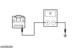 | Yes
GO to E2 . No VERIFY the SJB fuse 36 (5A) is OK. If OK, REPAIR the circuit. CLEAR the DTCs. CYCLE the ignition. REPEAT the self-test. If not OK, REFER to the Wiring Diagrams Manual to identify the possible causes of the circuit short. |
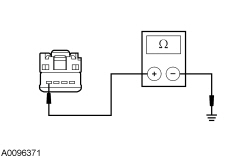
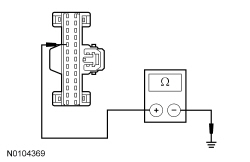
| E2 CHECK THE PATS TRANSCEIVER GROUND CIRCUIT FOR CONTINUITY | |
 | Yes
GO to E3 . No REPAIR the circuit. CLEAR the DTCs. CYCLE the ignition. REPEAT the self-test. |
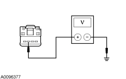
| E3 CHECK THE PATS TRANSCEIVER RECEIVE CIRCUIT FOR VOLTAGE | |
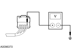 | Yes
GO to E6 . No GO to E4 . |
| E4 CHECK THE PATS TRANSCEIVER RECEIVE CIRCUIT FOR A SHORT TO GROUND | |
 | Yes
GO to E5 . No REPAIR the circuit. CLEAR the DTCs. CYCLE the ignition. REPEAT the self-test. If DTC B10D9:87 is retrieved again, GO to E12 . |
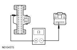
| E5 CHECK THE PATS TRANSCEIVER RECEIVE CIRCUIT FOR AN OPEN | |
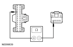 | Yes
GO to E12 . No REPAIR the circuit. CLEAR the DTCs. CYCLE the ignition. REPEAT the self-test. |
| E6 CHECK THE PATS TRANSCEIVER TRANSMIT CIRCUIT FOR VOLTAGE | |
NOTE: Replacement of the PATS transceiver does not require the PATS keys to be programmed into the IPC again. 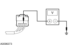 | Yes
INSTALL a new PATS transceiver. REFER to Passive Anti-Theft System (PATS) Transceiver in this section. CLEAR the DTCs. CYCLE the ignition. REPEAT the self-test. If DTC B10D9:87 is retrieved again, GO to E12 . No GO to E7 . |
| E7 CHECK THE PATS TRANSCEIVER TRANSMIT CIRCUIT FOR A SHORT TO GROUND WITH THE PATS TRANSCEIVER CONNECTED | |
 | Yes
GO to E9 . No GO to E8 . |
| E8 CHECK THE PATS TRANSCEIVER TRANSMIT CIRCUIT FOR A SHORT TO GROUND WITH THE PATS TRANSCEIVER DISCONNECTED | |
NOTE: Replacement of the PATS transceiver does not require the PATS keys to be programmed into the IPC again. | Yes
INSTALL a new PATS transceiver. REFER to Passive Anti-Theft System (PATS) Transceiver in this section. CLEAR the DTCs. CYCLE the ignition. REPEAT the self-test. No REPAIR the circuit. CLEAR the DTCs. CYCLE the ignition. REPEAT the self-test. |
| E9 CHECK THE PATS TRANSCEIVER TRANSMIT CIRCUIT FOR AN OPEN | |
 | Yes
GO to E10 . No REPAIR the circuit. CLEAR the DTCs. CYCLE the ignition. REPEAT the self-test. |
| E10 CHECK THE PATS TRANSCEIVER TRANSMIT CIRCUIT FOR VOLTAGE WHILE COMMANDED ON | |
NOTE: Replacement of the PATS transceiver does not require the PATS keys to be programmed into the IPC again. | Yes
INSTALL a new PATS transceiver. REFER to Passive Anti-Theft System (PATS) Transceiver in this section. CLEAR the DTCs. CYCLE the ignition. REPEAT the self-test. No GO to E11 . |
| E11 CHECK THE PATS TRANSCEIVER TRANSMIT CIRCUIT FOR A SHORT TO VOLTAGE | |
 | Yes
REPAIR the circuit. CLEAR the DTCs. CYCLE the ignition. REPEAT the self-test. No GO to E12 . |
| E12 CHECK FOR CORRECT IPC OPERATION | |
| Yes
INSTALL a new IPC . REFER to Section 413-01 . RESET the parameters in both the IPC and the PCM. REFER to Passive Anti-Theft System (PATS) Parameter Reset in this section. PROGRAM the PATS keys into the new IPC . REFER to Integrated Keyhead Transmitter (IKT) Key Programming Using Diagnostic Equipment in this section. CYCLE the ignition. REPEAT the self-test. No The system is operating correctly at this time. The concern may have been caused by a loose or corroded connector. CLEAR the DTCs. CYCLE the ignition. REPEAT the self-test. |
Pinpoint Test F: The Anti-Theft Indicator Is Always/Never On
The Passive Anti-Theft System (PATS) uses a visual anti-theft indicator located in the Instrument Panel Cluster (IPC). The anti-theft indicator proves out for 3 seconds when the key is turned to the ON or START position. If there is a PATS concern, the anti-theft indicator either flashes rapidly or glows steadily (for more than 3 seconds) when the key is turned to the ON or the START position. PATS also flashes the anti-theft indicator every 2 seconds at key off to act as a visual theft deterrent. The anti-theft indicator operation is controlled by the IPC .
This pinpoint test is intended to diagnose the following:
| Test Step | Result / Action to Take |
|---|---|
| F1 CHECK THE ANTI-THEFT INDICATOR FOR CORRECT OPERATION | |
| Yes
GO to F2 . No INSTALL a new IPC . REFER to Section 413-01 . RESET the parameters in both the IPC and the PCM. REFER to Passive Anti-Theft System (PATS) Parameter Reset in this section. PROGRAM the PATS keys into the new IPC . REFER to Integrated Keyhead Transmitter (IKT) Key Programming Using Diagnostic Equipment in this section. CYCLE the ignition. REPEAT the self-test. |
| F2 CHECK FOR CORRECT IPC OPERATION | |
| Yes
INSTALL a new IPC . REFER to Section 413-01 . RESET the parameters in both the IPC and the PCM. REFER to Passive Anti-Theft System (PATS) Parameter Reset in this section. PROGRAM the PATS keys into the new IPC . REFER to Integrated Keyhead Transmitter (IKT) Key Programming Using Diagnostic Equipment in this section. CYCLE the ignition. REPEAT the self-test. No The system is operating correctly at this time. The concern may have been caused by a loose or corroded connector. CLEAR the DTCs. CYCLE the ignition. REPEAT the self-test. |
Pinpoint Test G: DTC B10DA:86 and/or DTC U0100:00
Refer to Wiring Diagrams Cell 14 , Module Communications Network for schematic and connector information.
During each vehicle start sequence, when the key is turned to the START or ON position, the Passive Anti-Theft System (PATS) transceiver reads the PATS key identification code and sends the data to the Instrument Panel Cluster (IPC). If there is no communication on the High Speed Controller Area Network (HS-CAN) between the IPC and the PCM, DTCs U0100:00 and/or B10DA:86 can set in the IPC and the vehicle can experience a PATS no-start.
If DTC B10DA:61 is present, refer to DTC Charts in this section.
This pinpoint test is intended to diagnose the following:
| Test Step | Result / Action to Take |
|---|---|
| G1 CHECK THE BATTERY STATE OF CHARGE | |
| Yes
GO to G2 . No INSTALL a new battery. REFER to Section 414-01 . |
| G2 CHECK FOR MODULE COMMUNICATION ON THE HS-CAN | |
| Yes
REFER to Section 418-00 to diagnose the module that is not communicating with the scan tool. No GO to G3 . |
| G3 INSPECT THE HS-CAN CIRCUITRY | |
| Yes
GO to G4 . No REPAIR the HS-CAN circuitry as necessary. CLEAR the DTCs. CYCLE the ignition. REPEAT the self-test. TEST the system for normal operation. |
| G4 CHECK FOR CORRECT PCM OPERATION | |
| Yes
INSTALL a new PCM. REFER to Section 303-14 . RESET the parameters in both the IPC and the PCM. REFER to Passive Anti-Theft System (PATS) Parameter Reset in this section. CYCLE the ignition. REPEAT the self-test. TEST the system for normal operation. If the concern is still present, GO to G5 . No The system is operating correctly at this time. The concern may have been caused by a loose or corroded connector. CLEAR the DTCs. CYCLE the ignition. REPEAT the self-test. TEST the system for normal operation. |
| G5 CHECK FOR CORRECT IPC OPERATION | |
| Yes
INSTALL a new IPC . REFER to Section 413-01 . RESET the parameters in both the IPC and the PCM. REFER to Passive Anti-Theft System (PATS) Parameter Reset in this section. PROGRAM the PATS keys into the new IPC . REFER to Integrated Keyhead Transmitter (IKT) Key Programming Using Diagnostic Equipment in this section. CYCLE the ignition. REPEAT the self-test. TEST the system for normal operation. No The system is operating correctly at this time. The concern may have been caused by a loose or corroded connector. CLEAR the DTCs. CYCLE the ignition. REPEAT the self-test. TEST the system for normal operation. |
Pinpoint Test H: The Vehicle Does Not Start
During each vehicle start sequence, when the key is turned to the START or ON position, the Passive Anti-Theft System (PATS) transceiver reads the PATS key identification code and sends the data to the Instrument Panel Cluster (IPC). If there is a PATS concern, PATS DTCs should be set in the IPC and DTC P1260 in the PCM. If it is due to a starting system or driveability concern, there is no PATS DTCs in the IPC or the DTC P1260 in the PCM.
This pinpoint test is intended to diagnose the following:
| Test Step | Result / Action to Take |
|---|---|
| H1 CHECK FOR COMMUNICATION WITH THE PCM AND IPC | |
| Yes
GO to H2 . No REFER to Section 418-00 to diagnose the module that is not communicating with the scan tool. |
| H2 CHECK FOR IPC DTCs | |
| Yes
REFER to DTC Charts in this section. No The no-start condition is not PATS -related. REFER to Section 303-06 or the Powertrain Control/Emissions Diagnosis (PC/ED) manual to diagnose the cause of the no-start condition. |
Pinpoint Test I: DTC B10D7:05
During each vehicle start sequence, when the key is turned to the START or ON position, the Passive Anti-Theft System (PATS) transceiver reads the PATS key identification code and sends the data to the Instrument Panel Cluster (IPC). If there is an inoperative transponder in the Integrated Keyhead Transmitter (IKT) key that is in the ignition lock cylinder, or if there was a concern during the programming of the IKT key, DTC B10D7:05 can set, and the vehicle experiences a PATS no-start.
This pinpoint test is intended to diagnose the following:
| Test Step | Result / Action to Take |
|---|---|
| I1 CHECK BOTH PATS KEYS | |
NOTE: Check to make sure the new PATS keys are approved Ford encoded PATS keys. Unapproved PATS keys do not always operate correctly over various temperature ranges. ( PATS keys from Ford, Rotunda, Strattec or Huf are approved Ford PATS keys.)  | Yes
REPLACE the damaged key with the new key that was cut (if present), or CUT a new key to replace the damaged key. DISCARD the damaged key. PROGRAM the keys. REFER to Integrated Keyhead Transmitter (IKT) Key Programming Using Diagnostic Equipment in this section. CLEAR the DTCs. CYCLE the ignition. REPEAT the self-test. TEST the system for normal operation. No If other IPC DTCs are retrieved, REFER to Section 419-10 . If no IPC DTCs are retrieved, the system is OK. |