
FLU77-4 or equivalent


NUD105-R025D or equivalent
SECTION 419-03: Cruise Control
| 2014 Mustang Workshop Manual
|
DIAGNOSIS AND TESTING
| Procedure revision date: 01/07/2013
|
| Fluke 77-IV Digital Multimeter
FLU77-4 or equivalent |
| Vehicle Communication Module (VCM) and Integrated Diagnostic System (IDS) software with appropriate hardware, or equivalent scan tool
|
| Flex Probe Kit
NUD105-R025D or equivalent |
Principles of Operation
The cruise control system is controlled by the PCM. The cruise control system is designed to maintain a selected vehicle speed between 40 km/h (25 mph) and the maximum limited vehicle speed. The cruise control system is controlled by the steering wheel mounted switches (ON, OFF, SET+, SET-, RES (without audio controls), and RESUME (with audio controls)), the stoplamp switch, the clutch pedal cruise control deactivator switch (manual transmission), stoplamp switch and the cruise control deactivator switch (integral to the stoplamp switch). The steering wheel mounted switches are hardwired to the PCM through the clockspring.
The cruise control functions include:
Pressing and releasing the ON switch turns the cruise control system on. Pressing and releasing the SET+ or SET- switch while the vehicle is traveling at the desired speed activates the cruise control system.
Tapping the SET+ or the SET- switch while in the set mode increases or decreases the maintained vehicle speed by 1.6 km/h (1 mph) per tap. If either switch is pressed and held, the vehicle speed continues to accelerate (SET+) or decelerate (SET-) until the switch is released.
Pressing and releasing the OFF switch, or switching the ignition switch to the OFF position, turns the cruise control system off. Applying the brake pedal puts the cruise control system into the standby mode. Pressing the RES (without audio controls) or RESUME (with audio controls) switch when the cruise control system is in the standby mode causes the vehicle to accelerate to the last set speed. The RESUME switch does not function if the OFF switch is pressed or if the current vehicle speed is below the minimum operational speed.
The clutch pedal cruise control deactivator switch is used on vehicles equipped with a manual transmission. When the clutch pedal is applied with the vehicle cruise control system engaged, the normally closed switch opens and signals the PCM to deactivate the cruise control.
The cruise control deactivator switch is provided as an additional safety feature. When the brake pedal is applied, an electrical signal from the stoplamp circuit to the PCM deactivates the system. Under increased brake pedal effort, the cruise control deactivator switch opens and removes the ground signal from the PCM, releasing the throttle.
Whenever the cruise control system is engaged and active, a cruise control icon on the Instrument Panel Cluster (IPC) is illuminated.
The inputs to the PCM are the:
The outputs from the PCM are the:
The cruise control system throttle position is completely controlled by the PCM through the electronically-controlled throttle body. Cruise control electronics are contained entirely within the PCM.
When the cruise control system is active, the PCM corrects for deviations in the actual vehicle speed by proportionally moving the throttle plate. The PCM modulates the throttle to minimize error between actual and desired vehicle speed.
The PCM strategy uses the throttle control for smooth accelerations.
The PCM sends a message over the High Speed Controller Area Network (HS-CAN) to the IPC whenever the cruise control indicator should be turned on or off.
In the event of an OFF command or a deactivation request from any source, the cruise control system carries out a deactivation and immediately returns the throttle to the idle position.
The cruise control system provides self-diagnostics. The cruise control is disabled anytime an error is detected in the system. No IPC indicator or message center messages are displayed when faults occur. Fault codes are logged by the PCM.
An Electronic Throttle Control (ETC) system fault also causes the cruise control system to be disabled. In this case, an ETC system powertrain malfunction (wrench) warning indicator is displayed.
Additionally, the following conditions cause the cruise control system to deactivate:
Inspection and Verification
Visual Inspection Chart
| Mechanical | Electrical |
|---|---|
|
|
NOTE: Make sure to use the latest scan tool software release.
If the cause is not visually evident, connect the scan tool to the Data Link Connector (DLC).NOTE: The Vehicle Communication Module (VCM) LED prove-out confirms power and ground from the DLC are provided to the VCM .
If the scan tool does not communicate with the VCM :DTC Charts
Diagnostics in this manual assume a certain skill level and knowledge of Ford-specific diagnostic practices. Refer to Diagnostic Methods in Section 100-00 for information about these practices.
PCM DTC Chart
| DTCs | Description | Action |
|---|---|---|
| P0504 | Brake Switch A / B Correlation | GO to Pinpoint Test B . |
| P0572 | Brake Switch A Circuit Low | GO to Pinpoint Test B . |
| P0573 | Brake Switch A Circuit High | GO to Pinpoint Test B . |
| P0579 | Cruise Control Multifunction Input A Circuit Range/Performance | GO to Pinpoint Test C . |
| P0581 | Cruise Control Multifunction Input A Circuit High | GO to Pinpoint Test C . |
| All other DTCs | — | REFER to the Powertrain Control/Emissions Diagnosis (PC/ED) manual. |
Symptom Chart
Diagnostics in this manual assume a certain skill level and knowledge of Ford-specific diagnostic practices. Refer to Diagnostic Methods in Section 100-00 for information about these practices.
| Condition | Possible Sources | Action |
|---|---|---|
|
| |
|
|
|
|
| |
|
| |
|
|
|
Pinpoint Tests
Pinpoint Test A: The Cruise Control Is Inoperative
Diagnostics in this manual assume a certain skill level and knowledge of Ford-specific diagnostic practices. Refer to Diagnostic Methods in Section 100-00 for information about these practices.
Refer to Wiring Diagrams Cell 31 , Cruise Control for schematic and connector information.
The cruise control switches uses the PCM RUN/START voltage and the PCM ground. The cruise control functionality is controlled through the cruise control switches and is hardwired to the PCM through a signal and return circuit.
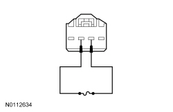
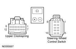
There are 5 cruise control switches with each switch operating a specific function that uses different resistance values. The PCM sends out a reference voltage to the cruise control switches and monitors the voltage drop when a cruise control switch is pressed. The voltage drop varies depending upon the resistance of each switch, providing a specific indication to the PCM which switch is pressed, activating and controlling the cruise control system.
The stoplamp switch is a single plunger 2 stage switch with 2 inputs to the PCM. When the brake pedal is applied, the first stage, which is a normally open stoplamp switch, closes and sends a voltage signal to the PCM deactivating the cruise control, if engaged. The second stage is the normally closed cruise control deactivator switch (integral to the stoplamp switch) opens and removes the ground signal to the PCM when the brake pedal is firmly applied. This is a redundant signal to the PCM. There is less than one millimeter in plunger travel between the first and second stage which the PCM monitors.
Vehicles equipped with a manual transmission have an additional clutch pedal cruise control deactivator switch. The clutch pedal cruise control deactivator switch provides a ground signal to the PCM. When the clutch pedal is applied the normally closed clutch pedal cruise control deactivator switch opens and removes the ground signal to the PCM which deactivates the cruise control, if engaged.
This pinpoint test is intended to diagnose the following:
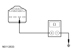
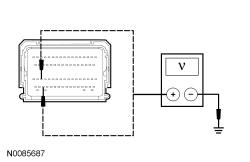
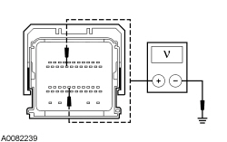
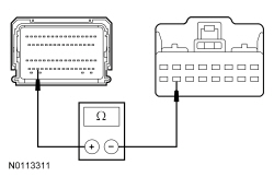
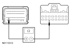
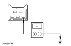
NOTICE: Use the correct probe adapter(s) when making measurements. Failure to use the correct probe adapter(s) may damage the connector.
NOTE: Failure to disconnect the battery when instructed will result in false resistance readings. Refer to Section 414-01 .
| Test Step | Result / Action to Take | ||||||||||||
|---|---|---|---|---|---|---|---|---|---|---|---|---|---|
| A1 CHECK FOR DTCs | |||||||||||||
| Yes
REFER to DTC Charts in this section. No GO to A2 . | ||||||||||||
| A2 CHECK FOR ABS MODULE DTCs | |||||||||||||
| Yes
REFER to Section 206-09 . REPAIR all ABS module DTCs and RETEST the system. No GO to A3 . | ||||||||||||
| A3 CHECK THE STOPLAMP SWITCH (BOO1) AND CRUISE CONTROL DEACTIVATOR SWITCH (BOO2) PIDs | |||||||||||||
| Yes
GO to A4 . No GO to Pinpoint Test B . | ||||||||||||
| A4 CHECK THE CRUISE CONTROL SWITCH | |||||||||||||
| Yes
If equipped with an automatic transmission, GO to A5 . If equipped with a manual transmission, GO to A6 . No If only one switch does not display the correct PID value, INSTALL a new cruise control switch. REFER to Cruise Control Switch in this section. TEST the system for normal operation. Otherwise, GO to Pinpoint Test C . | ||||||||||||
| A5 CHECK THE DIGITAL TR SENSOR PID | |||||||||||||
| Yes
GO to A9 . No REFER to Section 307-01 to diagnose the TR input concern. | ||||||||||||
| A6 CHECK THE CLUTCH PEDAL CRUISE CONTROL DEACTIVATOR SWITCH PID (CPP_TOP) | |||||||||||||
| Yes
GO to A9 . No GO to A7 . | ||||||||||||
| A7 CHECK THE CLUTCH PEDAL CRUISE CONTROL DEACTIVATOR SWITCH GROUND CIRCUIT FOR AN OPEN | |||||||||||||
 | Yes
GO to A8 . No REPAIR the circuit. TEST the system for normal operation. | ||||||||||||
| A8 CHECK THE CLUTCH PEDAL CRUISE CONTROL DEACTIVATOR SWITCH SIGNAL CIRCUIT FOR AN OPEN OR SHORT TO GROUND | |||||||||||||
 | Yes
INSTALL a new clutch pedal cruise control deactivator switch. REFER to Cruise Control Deactivator Switch in this section. TEST the system for normal operation. No REPAIR the circuit. TEST the system for normal operation. | ||||||||||||
| A9 CHECK FOR CORRECT PCM OPERATION | |||||||||||||
| Yes
INSTALL a new PCM. REFER to Section 303-14 . TEST the system for normal operation. No The system is operating correctly at this time. The concern may have been caused by a loose or corroded connector. |
Pinpoint Test B: DTC P0504, P0572 Or P0573
Diagnostics in this manual assume a certain skill level and knowledge of Ford-specific diagnostic practices. Refer to Diagnostic Methods in Section 100-00 for information about these practices.
Refer to Wiring Diagrams Cell 31 , Cruise Control for schematic and connector information.
The stoplamp switch is a single plunger 2 stage switch with 2 inputs to the PCM. When the brake pedal is applied, the first stage, which is a normally open stoplamp switch, closes and sends a voltage signal to the PCM deactivating the cruise control, if engaged. The second stage is the normally closed cruise control deactivator switch (integral to the stoplamp switch) opens and removes the ground signal to the PCM when the brake pedal is firmly applied. This is a redundant signal to the PCM. There is less than one millimeter in plunger travel between the first and second stage which the PCM monitors.
This pinpoint test is intended to diagnose the following:
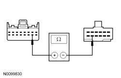
NOTICE: Use the correct probe adapter(s) when making measurements. Failure to use the correct probe adapter(s) may damage the connector.
NOTE: Failure to disconnect the battery when instructed will result in false resistance readings. Refer to Section 414-01 .
| Test Step | Result / Action to Take | ||||||||||||
|---|---|---|---|---|---|---|---|---|---|---|---|---|---|
| B1 CHECK THE OPERATION OF THE STOPLAMPS | |||||||||||||
| Yes
GO to B2 . No REFER to Section 417-01 to continue diagnosis of the stoplamps. | ||||||||||||
| B2 CHECK THE STOPLAMP SWITCH (BOO1) AND CRUISE CONTROL DEACTIVATOR SWITCH (BOO2) PIDs | |||||||||||||
| Yes
GO to B7 . No For an incorrect BOO1 PID value, GO to B3 . For an incorrect BOO2 PID value, GO to B4 . | ||||||||||||
| B3 CHECK THE STOPLAMP INPUT TO THE PCM | |||||||||||||
 | Yes
GO to B7 . No REPAIR the circuit for an open. CLEAR the DTCs. TEST the system for normal operation. | ||||||||||||
| B4 CHECK THE CRUISE CONTROL DEACTIVATOR SWITCH FOR CORRECT OPERATION | |||||||||||||
 | Yes
GO to B7 . No GO to B5 . | ||||||||||||
| B5 CHECK THE CRUISE CONTROL DEACTIVATOR SWITCH GROUND CIRCUIT FOR AN OPEN | |||||||||||||
 | Yes
GO to B6 . No REPAIR the circuit for an open. CLEAR the DTCs. TEST the system for normal operation. | ||||||||||||
| B6 CHECK THE CRUISE CONTROL DEACTIVATOR SWITCH SIGNAL CIRCUIT FOR AN OPEN | |||||||||||||
 | Yes
REMOVE the fused jumper wire. INSTALL a new stoplamp switch. REFER to Section 417-01 . CLEAR the DTCs. TEST the system for normal operation. No REMOVE the fused jumper wire. REPAIR the circuit. CLEAR the DTCs. TEST the system for normal operation. | ||||||||||||
| B7 CHECK FOR CORRECT PCM OPERATION | |||||||||||||
| Yes
INSTALL a new PCM. REFER to Section 303-14 . TEST the system for normal operation. No The system is operating correctly at this time. The concern may have been caused by a loose or corroded connector. CLEAR the DTCs. REPEAT the self-test. |
Pinpoint Test C: DTC P0579 Or DTC P0581
Diagnostics in this manual assume a certain skill level and knowledge of Ford-specific diagnostic practices. Refer to Diagnostic Methods in Section 100-00 for information about these practices.
Refer to Wiring Diagrams Cell 31 , Cruise Control for schematic and connector information.
The cruise control switches uses the PCM RUN/START voltage and the PCM ground. The cruise control functionality is controlled through the cruise control switches and is hardwired to the PCM through a signal and return circuit.
There are 5 cruise control switches with each switch operating a specific function that uses different resistance values. The PCM sends out a reference voltage to the cruise control switches and monitors the voltage drop when a cruise control switch is pressed. The voltage drop varies depending upon the resistance of each switch, providing a specific indication to the PCM which switch is pressed, activating and controlling the cruise control system.
This pinpoint test is intended to diagnose the following:
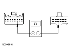
NOTICE: Use the correct probe adapter(s) when making measurements. Failure to use the correct probe adapter(s) may damage the connector.
| Test Step | Result / Action to Take | ||||||||||||
|---|---|---|---|---|---|---|---|---|---|---|---|---|---|
| C1 CHECK THE CRUISE CONTROL SWITCH | |||||||||||||
| Yes
GO to C11 . No If only one switch does not display the correct PID value, INSTALL a new cruise control switch. REFER to Cruise Control Switch in this section. CLEAR the DTCs. TEST the system for normal operation. Otherwise, GO to C2 . | ||||||||||||
| C2 CHECK THE CRUISE CONTROL SWITCH CIRCUITRY FOR A SHORT TO VOLTAGE | |||||||||||||
 | Yes
TURN the parking lamps off. GO to C3 . No TURN the parking lamps off. GO to C6 . | ||||||||||||
| C3 CHECK THE CRUISE CONTROL SWITCH CIRCUITRY FOR A SHORT TO VOLTAGE WITH THE CLOCKSPRING DISCONNECTED | |||||||||||||
| Yes
REPAIR the circuit in question. CLEAR the DTCs. TEST the system for normal operation. No TURN the parking lamps off. GO to C4 . | ||||||||||||
| C4 CHECK THE CLOCKSPRING FOR A SHORT TO VOLTAGE | |||||||||||||
| Yes
INSTALL a new clockspring. INSTALL the driver air bag module. REFER to Section 501-20B . CLEAR the DTCs. TEST the system for normal operation. No GO to C5 . | ||||||||||||
| C5 CHECK THE STEERING WHEEL CRUISE CONTROL CIRCUITRY FOR A SHORT TO VOLTAGE | |||||||||||||
 | Yes
REPAIR the circuit in question in the steering wheel harness. CLEAR the DTCs. TEST the system for normal operation. No INSTALL a new cruise control switch. REFER to Cruise Control Switch in this section. INSTALL the driver air bag module. REFER to Section 501-20B . CLEAR the DTCs. TEST the system for normal operation. | ||||||||||||
| C6 CHECK THE CRUISE CONTROL SWITCH CIRCUITRY FOR A SHORT TO GROUND | |||||||||||||
 | Yes
GO to C8 . No GO to C7 . | ||||||||||||
| C7 CHECK THE CLOCKSPRING FOR A SHORT TO GROUND | |||||||||||||
| Yes
INSTALL a new clockspring. INSTALL the driver air bag module. REFER to Section 501-20B . CLEAR the DTCs. TEST the system for normal operation. No GO to C10 . | ||||||||||||
| C8 CHECK THE CRUISE CONTROL SWITCH CIRCUITRY FOR AN OPEN | |||||||||||||
  | Yes
GO to C9 . No REPAIR the circuit in question. CLEAR the DTCs. TEST the system for normal operation. | ||||||||||||
| C9 CHECK THE CLOCKSPRING FOR AN OPEN | |||||||||||||
  | Yes
GO to C10 . No INSTALL a new clockspring. INSTALL the driver air bag module. REFER to Section 501-20B . CLEAR the DTCs. TEST the system for normal operation. | ||||||||||||
| C10 CHECK THE CIRCUITS TO THE STEERING WHEEL CONTROLS CIRCUITRY FOR AN OPEN OR SHORT TO GROUND | |||||||||||||
NOTE: Circuit (BN) does not need to be checked for a short to ground.
 | Yes
INSTALL a new cruise control switch. REFER to Cruise Control Switch in this section. INSTALL the driver air bag module. REFER to Section 501-20B . CLEAR the DTCs. TEST the system for normal operation. No INSTALL a new steering wheel. REFER to Section 211-04 . CLEAR the DTCs. TEST the system for normal operation. | ||||||||||||
| C11 CHECK FOR CORRECT PCM OPERATION | |||||||||||||
| Yes
INSTALL a new PCM. REFER to Section 303-14 . INSTALL the driver air bag module. REFER to Section 501-20B . TEST the system for normal operation. No The system is operating correctly at this time. The concern may have been caused by a loose or corroded connector. INSTALL the driver air bag module. REFER to Section 501-20B . CLEAR the DTCs. REPEAT the self-test. |
Pinpoint Test D: The Cruise Control Does Not Disengage When The Clutch Is Applied
Diagnostics in this manual assume a certain skill level and knowledge of Ford-specific diagnostic practices. Refer to Diagnostic Methods in Section 100-00 for information about these practices.
Refer to Wiring Diagrams Cell 31 , Cruise Control for schematic and connector information.
Vehicles equipped with a manual transmission have an additional clutch pedal cruise control deactivator additional clutch pedal cruise control deactivator the normally closed clutch pedal cruise control deactivator switch. When the clutch pedal is applied, the clutch pedal cruise control deactivator switch opens and removes the ground signal to the PCM disengaging the cruise control.
This pinpoint test is intended to diagnose the following:
NOTICE: Use the correct probe adapter(s) when making measurements. Failure to use the correct probe adapter(s) may damage the connector.
| Test Step | Result / Action to Take |
|---|---|
| D1 CHECK THE CPP SWITCH (CPP TOP) PID | |
| Yes
GO to D3 . No GO to D2 . |
| D2 CHECK THE CLUTCH PEDAL CRUISE CONTROL DEACTIVATOR SWITCH GROUND CIRCUIT FOR A SHORT TO GROUND | |
 | Yes
INSTALL a new clutch pedal cruise control deactivator switch. REFER to Cruise Control Deactivator Switch in this section. TEST the system for normal operation. No REPAIR the circuit. TEST the system for normal operation. |
| D3 CHECK FOR CORRECT PCM OPERATION | |
| Yes
INSTALL a new PCM. REFER to Section 303-14 . TEST the system for normal operation. No The system is operating correctly at this time. The concern may have been caused by a loose or corroded connector. |