
FLU77-4 or equivalent


300-NUD105-R025DE or equivalent
SECTION 419-10: Multifunction Electronic Modules
| 2014 Mustang Workshop Manual
|
DIAGNOSIS AND TESTING
| Procedure revision date: 01/07/2013
|
| Fluke 77-IV Digital Multimeter
FLU77-4 or equivalent |
| Vehicle Communication Module (VCM) and Integrated Diagnostic System (IDS) software with appropriate hardware, or equivalent scan tool
|
| Flex Probe Kit
300-NUD105-R025DE or equivalent |
Principles of Operation
NOTE: The Smart Junction Box (SJB) is also known as the Generic Electronic Module (GEM).
The SJB controls various systems by monitoring inputs from switches, sensors and messages sent from other modules on the Medium Speed Controller Area Network (MS-CAN). Based on the inputs received, the SJB activates outputs. For example, the SJB monitors the headlamp switch position. Based on this input, the SJB may provide voltage to the exterior lamps.
Field-Effect Transistor (FET) Protection
A Field-Effect Transistor (FET) is a type of transistor that when used with module software can be used to monitor and control current flow on module outputs. The FET protection strategy is used to prevent module damage in the event of excessive current flow.
The SJB utilizes an FET protective circuit strategy for many of its outputs (for example, a headlamp output circuit). Output loads (current level) are monitored for excessive current (typically short circuits) and are shut down (turns off the voltage or ground provided by the module) when a fault event is detected. A short circuit DTC is stored at the fault event and a cumulative counter is started.
When the demand for the output is no longer present, the module resets the FET circuit protection to allow the circuit to function. The next time the driver requests a circuit to activate that has been shut down by a previous short ( FET protection) and the circuit is still shorted, the FET protection shuts off the circuit again and the cumulative counter advances.
When the excessive circuit load occurs often enough, the module shuts down the output until a repair procedure is carried out. Each FET protected circuit has 3 predefined levels of short circuit tolerance based on the harmful effect of each circuit fault on the FET and the ability of the FET to withstand it. A module lifetime level of fault events is established based upon the durability of the FET . If the total tolerance level is determined to be 600 fault events, the 3 predefined levels would be 200, 400 and 600 fault events.
When each tolerance level is reached, the short circuit DTC that was stored on the first failure cannot be cleared by a command to clear the continuous DTCs. The module does not allow this code to be cleared or the circuit restored to normal operation until a successful self-test proves that the fault has been repaired. After the self-test has successfully completed (no on-demand DTCs present), DTC B106E and the associated DTC (the DTC related to the shorted circuit) automatically clears and the circuit function returns.
When each level is reached, the DTC associated with the short circuit sets along with DTC B106E. These DTCs can be cleared using the module on-demand self-test, then the Clear DTC operation on the scan tool (if the on-demand test shows the fault corrected). The module never resets the fault event counter to zero and continues to advance the fault event counter as short circuit fault events occur.
If the number of short circuit fault events reach the third level, then DTCs B106F and B1342 set along with the associated short circuit DTC. DTC B106F cannot be cleared and the module must be replaced after the repair.
Inspection and Verification
Visual Inspection Chart
| Electrical |
|---|
|
NOTE: Make sure to use the latest scan tool software release.
If the cause is not visually evident, connect the scan tool to the Data Link Connector (DLC).NOTE: The Vehicle Communication Module (VCM) LED prove-out confirms power and ground from the DLC are provided to the VCM .
If the scan tool does not communicate with the VCMDTC Charts
Smart Junction Box (SJB) DTC Chart
| DTC | Description | Action |
|---|---|---|
| B106B | Tire Pressure Sensor Low Battery | REFER to Section 204-04 . |
| B106D | Tire Pressure Monitor System (TPMS) Initiators Not Configured | REFER to Section 204-04 . |
| B106E | Solid State Driver Disabled Due to Short Circuit | GO to Pinpoint Test A . |
| B106F | Module Disabled Due to External Fault | GO to Pinpoint Test A . |
| B1138 | Memory Full | REFER to Section 419-01B . |
| B1139 | Invalid Transmitter Identification Code | REFER to Section 501-14 . |
| B1302 | Accessory Delay Relay Coil Circuit Failure | REFER to Section 501-11 . |
| B1304 | Accessory Delay Relay Coil Circuit Short To Battery | REFER to Section 501-11 . |
| B1317 | Battery Voltage High | GO to Pinpoint Test B . |
| B1318 | Battery Voltage Low | GO to Pinpoint Test C . |
| B1320 | Driver Door Ajar Circuit Open | REFER to Section 417-02 . |
| B1328 | Passenger Door Ajar Circuit Open | REFER to Section 417-02 . |
| B1331 | Decklid Ajar Rear Door Circuit Failure | REFER to Section 417-02 . |
| B1342 | ECU Is Faulted | DIAGNOSE all other DTCs first. If no other DTCs are present, INSTALL a new SJB . REFER to Smart Junction Box (SJB) in this section. TEST the system for normal operation. |
| B1352 | Ignition Key-In Circuit Failure | REFER to Section 413-01 . |
| B1472 | Lamp Headlamp Input Circuit Short To Ground | REFER to Section 417-01 . |
| B1485 | Brake Pedal Input Short To Battery | REFER to Section 417-01 . |
| B1510 | Flash To Pass Switch Circuit Short To Ground | REFER to Section 417-01 . |
| B1520 | Hood Switch Circuit Open | REFER to Section 419-01A . |
| B1578 | Lamp Park Input Circuit Short To Ground | REFER to Section 417-01 . |
| B1688 | Lamp Dome Input Circuit Short To Ground | REFER to Section 417-02 . |
| B1696 | Autolamp On Circuit Short To Ground | REFER to Section 417-01 . |
| B1791 | Autolamp Sensor Input Circuit Open | REFER to Section 417-01 . |
| B1793 | Autolamp Sensor Input Circuit Short to Ground | REFER to Section 417-01 . |
| B2008 | Wipers On Signal Circuit Short to Ground | REFER to Section 417-01 . |
| B2044 | Left Rear Stop Lamp Circuit Short To Ground | REFER to Section 417-01 . |
| B2046 | Right Rear Stop Lamp Circuit Short To Ground | REFER to Section 417-01 . |
| B2048 | Left Rear Turn Lamp Circuit Short To Ground | REFER to Section 417-01 . |
| B2050 | Right Rear Turn Lamp Circuit Short To Ground | REFER to Section 417-01 . |
| B2071 | Hazard Switch Signal Short To Ground | REFER to Section 417-01 . |
| B2100 | Door Driver Key Cylinder Switch Failure | REFER to Section 419-01A . |
| B2212 | Panel Dim Switch Out of Range | REFER to Section 413-00 . |
| B2254 | Front Fog Lamp Switch Failure | REFER to Section 417-01 . |
| B2276 | Less Than 2 Transmitters Programmed | REFER to Section 501-14 . |
| B2281 | Right Turn Switch Short To Ground | REFER to Section 417-01 . |
| B2282 | Left Turn Switch Short To Ground | REFER to Section 417-01 . |
| B2425 | Remote Keyless Entry Out of Synchronization | REFER to Section 501-14 . |
| B2477 | Module Configuration Failure | CARRY OUT Programmable Module Installation (PMI) on the SJB . REFER to Section 418-01 . |
| B2479 | Park Brake Switch Circuit Short To Ground | REFER to Section 413-01 . |
| B2494 | Anti-Theft Horn Output Circuit Short to Battery | Diagnose all other DTCs and symptoms before proceeding.
Using as built data, CARRY out Programmable Module Installation (PMI) on the SJB . REFER to Section 418-01 . CLEAR the DTCs and verify successful module configuration. REPEAT the self-test. If DTC B2494 is retrieved again, INSTALL a new SJB . REFER to Smart Junction Box (SJB) in this section. |
| B2498 | Headlamp Switch Multiple Signals Input Active | REFER to Section 417-01 . |
| B2572 | Brake Shift Interlock Output Circuit Failure | REFER to Section 307-05 . |
| B2844 | Ignition Fault | REFER to Section 211-05 . |
| B2868 | Left Front Tire Pressure Sensor Fault | REFER to Section 204-04 . |
| B2869 | Right Front Tire Pressure Sensor Fault | REFER to Section 204-04 . |
| B2870 | Right Rear Tire Pressure Sensor Fault | REFER to Section 204-04 . |
| B2871 | Left Rear Tire Pressure Sensor Fault | REFER to Section 204-04 . |
| B2872 | Tire Pressure Sensor Fault | REFER to Section 204-04 . |
| B287A | Tire Pressure System Fault | REFER to Section 204-04 . |
| B2A20 | Ignition Stuck in START | REFER to Section 211-05 . |
| B2A21 | One or More Configuration Files Missing or Corrupt | CARRY out Programmable Module Installation (PMI) on the SJB . REFER to Section 418-01 . CLEAR the DTCs. REPEAT the self-test. If DTC B2A21 is retrieved again, INSTALL a new SJB . REFER to Smart Junction Box (SJB) in this section. TEST the system for normal operation. |
| B2A22 | Headlamp OFF Circuit Open | REFER to Section 417-01 . |
| B2A23 | High Beam Input Circuit Short To Ground | REFER to Section 417-01 . |
| B2A24 | Turn Signal Input Circuit Failure | REFER to Section 417-01 . |
| B2A25 | Trim Panel Lock Switch Circuit Failure | REFER to Section 501-14 . |
| B2A27 | Right Front Turn Lamp Circuit Open | REFER to Section 417-01 . |
| B2A28 | Right Front Turn Lamp Circuit Short to Ground | REFER to Section 417-01 . |
| B2A29 | Left Front Turn Lamp Circuit Open | REFER to Section 417-01 . |
| B2A2A | Left Front Turn Lamp Circuit Short to Ground | REFER to Section 417-01 . |
| B2A2B | Left Corner Lamp Output Circuit Short to Ground | REFER to Section 417-01 . |
| B2A2C | Right Corner Lamp Output Circuit Short to Ground | REFER to Section 417-01 . |
| B2A2E | Right Front Lamp Low Beam Circuit Open | REFER to Section 417-01 . |
| B2A2F | Right Front Lamp Low Beam Circuit Short to Ground | REFER to Section 417-01 . |
| B2A30 | Left Front Lamp Low Beam Circuit Open | REFER to Section 417-01 . |
| B2A31 | Left Front Lamp Low Beam Circuit Short to Ground | REFER to Section 417-01 . |
| B2A32 | LED Backlighting Output Circuit Open | REFER to Section 413-00 . |
| B2A33 | LED Backlighting Output Circuit Short to Ground | REFER to Section 413-00 . |
| B2A35 | Interior Lighting Output Circuit Open | REFER to Section 417-02 . |
| B2A36 | Interior Lighting Output Circuit Short to Ground | REFER to Section 417-02 . |
| B2A38 | Floor Lamp Output Circuit Short to Ground | REFER to Section 417-02 . |
| B2A3A | Puddle Lamp Output Circuit Short to Ground | REFER to Section 417-02 . |
| P062F | Internal Control Module EEPROM Error | CLEAR the DTCs. REPEAT the self-test. If DTC P062F is retrieved again, INSTALL a new SJB . REFER to Smart Junction Box (SJB) in this section. TEST the system for normal operation. |
| C1125 | Brake Fluid Level Sensor Input Circuit Failure | REFER to Section 413-01 . |
| C2780 | ECU in Manufacturer Sub-State | REFER to Section 204-04 . |
| U0155 | Lost Communication With Instrument Panel Cluster (IC) Control Module | GO to Pinpoint Test D . |
| U2050 | No Application Present | CARRY out Programmable Module Installation (PMI) on the SJB . REFER to Section 418-01 . CLEAR the DTCs. REPEAT the self-test. If DTC U2050 is retrieved again, INSTALL a new SJB . REFER to Smart Junction Box (SJB) in this section. TEST the system for normal operation. |
| U2472 | Unexpected Ignition State | REFER to Section 211-05 . |
| U2473 | Unexpected Vehicle Speed (VSS) | NOTE: Sets during the self-test if vehicle speed exceeds 3 mph (5 kph) or vehicle speed cannot be determined by the SJB . VERIFY the speedometer operates correctly.If the speedometer does not operate correctly, REFER to Section 413-01 . If the speedometer operates correctly, the self-test is carried out while the vehicle is moving. STOP the vehicle and REPEAT the self-test. |
Symptom Chart
| Condition | Possible Sources | Action |
|---|---|---|
|
|
|
Pinpoint Tests
Pinpoint Test A: DTCs B106E, B106F
The Smart Junction Box (SJB) controls the output of several vehicle systems by means of solid state drivers. A DTC sets when an overload occurs on any of these drivers. The module also tracks the number of repetitive faults on each of these circuits, and then it compares said number of overloads to 3 progressive thresholds established for each circuit. If the third threshold has not been met, the DTC for the affected circuit can be cleared by eliminating the fault, clearing the DTCs and then running a self-test.
At the point that each of the first 2 thresholds is met, DTC B106E sets along with a DTC related to the affected circuit. Once the final (third) threshold has been met, the affected output is permanently disabled, and DTC B106F sets, at which time the SJB must be replaced.
When DTC B1342 is set because the module has reached a third threshold and the SJB has permanently disabled an output, no DTCs can be cleared from the SJB . Using the module self-test to confirm a repair is not possible and a measurement using a digital multimeter of the affected output circuit is required to make sure the fault condition no longer exists.
This pinpoint test is intended to diagnose the following:
| Test Step | Result / Action to Take |
|---|---|
| A1 REVIEW THE DTCs | |
NOTICE: First follow the necessary diagnostics to resolve DTC B106E and any other present DTCs (ignoring B106F). DTC B106E is only present when there is another DTC due to software or circuitry issues that must be resolved before another self-test is run. DTC B106F is only present once the final threshold has been met. Failure to correct the fault condition first may cause damage to the new SJB , resulting in a repeat repair. | Yes
CORRECT the DTCs. REFER to the Smart Junction Box (SJB) DTC chart in this section. After the repair, GO to A2 . No GO to A2 . |
| A2 REPEAT THE SJB SELF-TEST | |
| Yes
INSTALL a new SJB . REFER to Smart Junction Box (SJB) in this section. TEST the system for normal operation. No The system is operating correctly at this time. The circuit short has been repaired. |
Pinpoint Test B: DTC B1317
Refer to Wiring Diagrams Cell 13 , Power Distribution/SJB for schematic and connector information.
This pinpoint test is intended to diagnose the following:
NOTE: DTC B1317 may be stored in the module memory due to previous battery charging or vehicle jump starting events.
| Test Step | Result / Action to Take |
|---|---|
| B1 CHECK FOR DTCs B1317, B1676 OR P0563 SET IN OTHER MODULES | |
| Yes
REFER to Section 414-00 to diagnose an overcharging condition. No GO to B2 . |
| B2 CHECK THE BATTERY VOLTAGE | |
| Yes
REFER to Section 414-00 to diagnose an overcharging condition. No GO to B3 . |
| B3 RECHECK FOR DTC B1317 | |
| Yes
INSTALL a new SJB . REFER to Smart Junction Box (SJB) in this section. TEST the system for normal operation. No The system is operating normally at this time. The DTC may have been set previously during battery charging or while jump starting the vehicle. |
Pinpoint Test C: DTC B1318
Refer to Wiring Diagrams Cell 13 , Power Distribution/SJB for schematic and connector information.
This pinpoint test is intended to diagnose the following:
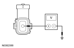
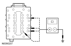
NOTICE: Use the correct probe adapter(s) when making measurements. Failure to use the correct probe adapter(s) may damage the connector.
NOTE: Failure to disconnect the battery when instructed results in false resistance readings. Refer to Section 414-01 .
| Test Step | Result / Action to Take | ||||||||||
|---|---|---|---|---|---|---|---|---|---|---|---|
| C1 RECHECK THE SJB DTCs | |||||||||||
| Yes
GO to C2 . No The system is operating normally at this time. The DTC may have been set due to a previous low battery voltage condition. | ||||||||||
| C2 CHECK FOR CHARGING SYSTEM DTCs IN THE PCM | |||||||||||
| Yes
REFER to Section 414-00 . No GO to C3 . | ||||||||||
| C3 CHECK THE BATTERY CONDITION AND STATE OF CHARGE | |||||||||||
| Yes
GO to C4 . No REFER to Section 414-00 . | ||||||||||
| C4 CHECK THE SJB VOLTAGE PID | |||||||||||
| Yes
GO to C7 . No GO to C5 . | ||||||||||
| C5 CHECK THE SJB VOLTAGE SUPPLY | |||||||||||
 | Yes
GO to C6 . No REPAIR circuit SBB01 (RD) for high resistance. CLEAR the DTC. REPEAT the self-test. | ||||||||||
| C6 CHECK THE SJB GROUND CIRCUIT FOR HIGH RESISTANCE | |||||||||||
 | Yes
GO to C7 . No REPAIR the ground circuit in question for high resistance. CLEAR the DTC. REPEAT the self-test. | ||||||||||
| C7 CHECK FOR CORRECT SJB OPERATION | |||||||||||
| Yes
INSTALL a new SJB . REFER to Smart Junction Box (SJB) in this section. TEST the system for normal operation. No The system is operating correctly at this time. The concern may have been caused by a loose or corroded connector. |
Pinpoint Test D: DTC U0155
This pinpoint test is intended to diagnose the following:
| Test Step | Result / Action to Take |
|---|---|
| D1 VERIFY CUSTOMER CONCERN | |
| Yes
GO to D2 . No The system is operating normally at this time. The DTC may have been set due to high network traffic or an intermittent fault condition. |
| D2 CHECK THE COMMUNICATION NETWORK | |
| Yes
GO to D3 . No REFER to Section 418-00 , The IPC Does Not Respond To The Scan Tool. |
| D3 RETRIEVE THE RECORDED DTCs FROM THE SJB SELF-TEST | |
| Yes
For DTC B1317, GO to Pinpoint Test B . For DTC B1318, GO to Pinpoint Test C . No GO to D4 . |
| D4 RECHECK THE SJB DTCs | |
NOTE: If new modules were installed prior to the DTC being set, the module configuration may be incorrectly set during Programmable Module Installation (PMI) or the PMI may not have been carried out. | Yes
GO to D5 . No The system is operating correctly at this time. The DTC may have been set due to high network traffic or an intermittent fault condition. |
| D5 CHECK FOR DTC U0155 SET IN OTHER MODULES | |
| Yes
INSTALL a new IPC . REFER to Section 413-01 . No INSTALL a new SJB . REFER to Smart Junction Box (SJB) in this section. |