
105-R025D or equivalent

FLU77-4 or equivalent

SGT27000 or equivalent 250-300 mA incandescent bulb test lamp

software with appropriate hardware, or equivalent scan tool
SECTION 501-11: Glass, Frames and Mechanisms
| 2014 Mustang Workshop Manual
|
DIAGNOSIS AND TESTING
| Procedure revision date: 01/07/2013
|
| Flex Probe Kit
105-R025D or equivalent |
| Fluke 77-IV Digital Multimeter
FLU77-4 or equivalent |
| Test Light
SGT27000 or equivalent 250-300 mA incandescent bulb test lamp |
| Vehicle Communication Module (VCM) and Integrated Diagnostic System (IDS)
software with appropriate hardware, or equivalent scan tool |
Principles of Operation
Power Window Control
Each door window motor is a 7-pin motor with integral electronics and must be initialized whenever a new window motor has been installed. Initialization is required to learn the full UP position and the profile of the glass as it travels through the glass channel. Once initialized, obstacle detection is enabled. When mechanical repairs have been carried out on the window regulator or glass run, the window motor must be de-initialized, and then initialized. The window control switch sends 2 separate signals to the window motor: up and down. When the window control switch is pressed to the first detent position, a 12-volt signal is sent to the window motor to request an up or down operation. When auto up or auto down is requested (switch pressed to the second detent position), the window control switch provides a 12-volt signal on both the up and down line simultaneously. During an auto up or auto down request, the window motor determines intended window direction by the signal first received. If the window control switch is pressed too quickly to the second detent position (less than 5 milliseconds of time between first detent signal and second detent signal), the window motor will not be able to determine the intended direction request and will not operate until the window control switch is released and pressed again. The up and down contacts are floating within the window control switch when the switch is in the neutral position. The up and down feeds to the window motor are all low current.
When the window motor is operating in auto up or auto down mode, movement of the window can be stopped by pressing the switch to any position (up, down, auto up, auto down). The window control switch must be released before the window will move again.
If there is an open in the window control switch or the associated wiring, the related function will become inoperative. If the up contact of the switch or the associated wiring develops an open circuit, the window will only operate in the down direction. If the down contact of the switch or the associated wiring develops an open circuit, the window will only operate in the up direction.
A new window motor will not operate in one-touch up mode, and the bounce-back feature will be disabled prior to initialization. If the switch is actuated to the auto UP or auto DOWN position and released, window movement will stop when the up or down contact in the window control switch is released. If the window motor is removed from the window regulator drum housing, or if a new window motor is installed, it must be initialized. Refer to Window Motor Initialization in this section.
The window motor will automatically adjust to system changes throughout its life: changes in seal drag and slight changes in the full OPEN position will occur and will be automatically compensated for. Once initialized, the window motor will soft stall into the upper and lower positions contributing to extended durability of the system. If the window does not seal completely in the full UP position (very small gaps/non bounce-back events only), the window switch can be actuated to the UP position and the window will be energized for a fraction of a second to fully seal and this new position will be learned.
Bounce-Back
The window motor has a bounce-back feature. If an obstacle has been detected in the window opening as the window glass is moving upward, the window motor will automatically reverse direction and move the glass toward the bounce-back position (in both up and one-touch up modes). If an obstruction occurs between 4 mm (0.15 in) and 200 mm (7.87 in) of window opening, the bounce-back position will be 250 mm (9.84 in) of window opening. If an obstruction occurs at a position greater than 200 mm (7.87 in) of window opening, the bounce-back position will be 50 mm (1.96 in) below where the obstruction occurred.
Security Override
To override a bounce-back condition (to overcome the resistance of ice on the window or seals for example), within 2 seconds after the window reaches the bounce-back position, pull and hold the window control switch. The window will travel up with no bounce-back or pinch protection. If the window control switch is released before the window is fully closed, the window will stop. If the ignition switch is turned to OFF or START (without delayed accessory), the window motor will stop.
Rear Window Defrost
When the rear window defrost switch (integral to the Front Controls Interface Module (FCIM)) is pressed, a message is sent to the HVAC module through the Controller Area Network (CAN). When the HVAC module receives the rear window defrost request, it will activate the rear window defrost relay located in the Battery Junction Box (BJB). When the rear window defrost relay is active, the rear window defrost grid will be energized.
Delayed Accessory Power
The accessory delay relay (located in the Smart Junction Box (SJB)) supplies voltage to operate the power windows. The SJB activates the accessory delay relay whenever the ignition switch is in the RUN or the ACCESSORY position, or when the ignition switch is changed from RUN or ACCESSORY to the OFF/LOCK position and the LH and RH doors are closed.
Convertible Power Rear Quarter Window Operation
For convertible, when the convertible top switch is operated (to raise or lower the convertible top), the Body Control Module B (BCM-B) sends a signal to the window motors to activate a full down operation of all 4 windows. The BCM-B will disable/inhibit the rear quarter window control switch from operating the rear quarter windows when the convertible top ajar switch indicates the convertible top is not in the full UP or full DOWN position.
Inspection and Verification
Visual Inspection Chart
| Mechanical | Electrical |
|---|---|
|
|
NOTE: Make sure to use the latest scan tool software release.
If the cause is not visually evident, connect the scan tool to the Data Link Connector (DLC).NOTE: The Vehicle Communication Module (VCM) LED prove out confirms power and ground from the DLC are provided to the VCM .
If the scan tool does not communicate with the VCM :NOTE: The SJB may also be identified as the Generic Electronic Module (GEM).
Clear the CMDTCs and carry out the self-test diagnostics for the BCM-B , SJB and HVAC module.DTC Charts
NOTE: This module utilizes a 5-character DTC followed by a 2-character failure type code. The failure type code provides information about specific fault conditions such as opens or shorts to ground. Continuous Memory Diagnostic Trouble Codes (CMDTCs) have an additional 2-character DTC status code suffix to assist in determining DTC history.
Body Control Module B (BCM-B) DTC Chart
| DTC | Description | Action |
|---|---|---|
| B126D:15 | Convertible/Folding Top Fully Down Position Switch : Circuit Short to Battery or Open | GO to Pinpoint Test J . |
| B1269:11 | Convertible/Folding Top Fully Up Position Switch : Circuit Short to Ground | GO to Pinpoint Test J . |
| B127A:12 | Global Window Control : Circuit Short to Battery | GO to Pinpoint Test G . |
| B127A:14 | Global Window Control : Circuit Short to Ground or Open | GO to Pinpoint Test G . |
| All other DTCs | — | REFER to the Master DTC Chart in Section 419-10 . |
NOTE: This module utilizes a 5-character DTC followed by a 2-character failure type code. The failure type code provides information about specific fault conditions such as opens or shorts to ground. Continuous Memory Diagnostic Trouble Codes (CMDTCs) have an additional 2-character DTC status code suffix to assist in determining DTC history.
HVAC Module DTC Chart
| DTC | Description | Action |
|---|---|---|
| B1C83:11 | Rear Defog Relay : Circuit Short to Ground | GO to Pinpoint Test D . |
| B1C83:12 | Rear Defog Relay : Circuit Short to Battery | GO to Pinpoint Test E . |
| B1C83:13 | Rear Defog Relay : Circuit Open | GO to Pinpoint Test D . |
| All other DTCs | — | REFER to the Master DTC Chart in Section 412-00 . |
Smart Junction Box (SJB) DTC Chart
| DTC | Description | Action |
|---|---|---|
| B1302 | Accessory Delay Relay Coil Circuit Failure | If the accessory delay relay is always on,
GO to Pinpoint Test I
.
If the accessory delay relay is inoperative, GO to Pinpoint Test H . |
| B1304 | Accessory Delay Relay Coil Circuit Short To Battery | GO to Pinpoint Test H . |
| All other DTCs | — | REFER to the Master DTC Chart in Section 419-10 . |
Symptom Chart
| Condition | Possible Sources | Action |
|---|---|---|
|
| |
|
| |
|
|
|
|
| |
|
| |
|
| |
|
| |
|
| |
|
| |
|
| |
|
|
|
|
| |
|
| |
|
|
Pinpoint Tests
Pinpoint Test A: A Single Power Window is Inoperative — LH Front
Refer to Wiring Diagrams Cell 100 , Power Windows for schematic and connector information.
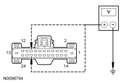
Under normal operation, the LH front power window motor receives high current power at all times through circuit SBB34 (YE/RD). Ground is provided to the LH front power window motor through circuit GD133 (BK). The LH front power window control switch and LH front power window motor receive low current power from the accessory delay relay through circuit CBP41 (BU). When the LH front window control switch is operated in the UP position, the LH front window motor receives a voltage signal through circuit CPW11 (BU/GY). When the LH front window control switch is operated in the DOWN position, the LH front window motor receives a voltage signal through circuit CPW10 (YE/VT).
NOTICE: Use the correct probe adapter(s) when making measurements. Failure to use the correct probe adapter(s) may damage the connector.
| Test Step | Result / Action to Take |
|---|---|
| A1 CHECK THE POWER TO THE LH WINDOW MOTOR | |
 | Yes
GO to A2 . No VERIFY Battery Junction Box (BJB) fuse 34 (30A) is OK. If OK, REPAIR the circuit. DE-INITIALIZE then INITIALIZE the LH front window motor. REFER to Window Motor Initialization in this section. TEST the system for normal operation. If not OK, REFER to the Wiring Diagrams manual to identify the possible causes of the circuit short. REPAIR the circuit. TEST the system for normal operation. |
| A2 CHECK THE LH FRONT WINDOW MOTOR DELAYED ACCESSORY FEED | |
 | Yes
GO to A3 . No REPAIR the circuit. DE-INITIALIZE then INITIALIZE the LH front window motor. REFER to Window Motor Initialization in this section. TEST the system for normal operation. |
| A3 CHECK THE LH FRONT WINDOW MOTOR GROUND | |
 | Yes
GO to A4 . No REPAIR the circuit. DE-INITIALIZE then INITIALIZE the LH front window motor. REFER to Window Motor Initialization in this section. TEST the system for normal operation. |
| A4 CHECK CIRCUIT CPW10 (YE/VT) FOR AN OPEN | |
 | Yes
GO to A5 . No REPAIR the circuit. DE-INITIALIZE then INITIALIZE the LH front window motor. REFER to Window Motor Initialization in this section. TEST the system for normal operation. |
| A5 CHECK CIRCUIT CPW11 (BU/GY) FOR AN OPEN | |
 | Yes
GO to A6 . No REPAIR the circuit. DE-INITIALIZE then INITIALIZE the LH front window motor. REFER to Window Motor Initialization in this section. TEST the system for normal operation. |
| A6 CHECK THE LH FRONT WINDOW CONTROL SWITCH | |
| Yes
INSTALL a new LH front window motor. REFER to Window Regulator Motor — Front Door in this section. INITIALIZE the LH front window motor. REFER to Window Motor Initialization in this section. TEST the system for normal operation. No INSTALL a new LH front window control switch. REFER to Window Control Switch in this section. DE-INITIALIZE then INITIALIZE the LH front window motor. REFER to Window Motor Initialization in this section. TEST the system for normal operation. |
Pinpoint Test B: A Single Power Window is Inoperative — RH Front
Refer to Wiring Diagrams Cell 100 , Power Windows for schematic and connector information.
Under normal operation, the RH front power window motor receives high current power at all times through circuit SBB29 (GY/RD). Ground is provided to the RH front power window motor through circuit GD139 (BK/YE). The RH front power window motor receives low current power from the accessory delay relay through circuit CBP41 (BU). Voltage is supplied to the LH and RH front window control switch through circuit CBP41 (BU). When the LH front or RH front window control switch is operated in the UP position, the RH front window motor receives a voltage signal through circuit CPW13 (BN/YE). When the RH front or LH front window control switch is operated in the DOWN position, the RH front window motor receives a voltage signal through circuit CPW12 (GN/OG).
NOTICE: Use the correct probe adapter(s) when making measurements. Failure to use the correct probe adapter(s) may damage the connector.
| Test Step | Result / Action to Take |
|---|---|
| B1 CHECK THE RH FRONT WINDOW OPERATION FROM THE LH FRONT WINDOW CONTROL SWITCH | |
| Yes
GO to B8 . No GO to B2 . |
| B2 CHECK THE POWER TO THE WINDOW MOTOR | |
| Yes
GO to B3 . No VERIFY Battery Junction Box (BJB) fuse 29 (30A) is OK. If OK, REPAIR the circuit. DE-INITIALIZE then INITIALIZE the RH front window motor. REFER to Window Motor Initialization in this section. TEST the system for normal operation. If not OK, REFER to the Wiring Diagrams manual to identify the possible causes of the circuit short. REPAIR the circuit. TEST the system for normal operation. |
| B3 CHECK THE RH FRONT WINDOW MOTOR DELAYED ACCESSORY FEED | |
| Yes
GO to B4 . No REPAIR the circuit. DE-INITIALIZE then INITIALIZE the RH front window motor. REFER to Window Motor Initialization in this section. TEST the system for normal operation. |
| B4 CHECK THE RH FRONT WINDOW MOTOR GROUND | |
| Yes
GO to B5 . No REPAIR the circuit. DE-INITIALIZE then INITIALIZE the RH front window motor. REFER to Window Motor Initialization in this section. TEST the system for normal operation. |
| B5 CHECK CIRCUIT CPW12 (GN/OG) FOR AN OPEN | |
 | Yes
GO to B6 . No REPAIR the circuit. DE-INITIALIZE then INITIALIZE the RH front window motor. REFER to Window Motor Initialization in this section. TEST the system for normal operation. |
| B6 CHECK CIRCUIT CPW13 (BN/YE) FOR AN OPEN | |
 | Yes
GO to B7 . No REPAIR the circuit. DE-INITIALIZE then INITIALIZE the RH front window motor. REFER to Window Motor Initialization in this section. TEST the system for normal operation. |
| B7 CHECK THE LH FRONT WINDOW CONTROL SWITCH | |
| Yes
INSTALL a new RH front window motor. REFER to Window Regulator Motor — Front Door in this section. INITIALIZE the RH front window motor. REFER to Window Motor Initialization in this section. TEST the system for normal operation. No INSTALL a new LH front window control switch. REFER to Window Control Switch in this section. DE-INITIALIZE then INITIALIZE the RH front window motor. REFER to Window Motor Initialization in this section. TEST the system for normal operation. |
| B8 CHECK THE POWER TO THE RH FRONT WINDOW CONTROL SWITCH | |
 | Yes
GO to B9 . No REPAIR the circuit. DE-INITIALIZE then INITIALIZE the RH front window motor. REFER to Window Motor Initialization in this section. TEST the system for normal operation. |
| B9 CHECK CIRCUIT CPW12 (GN/OG) FOR AN OPEN | |
 | Yes
GO to B10 . No REPAIR the circuit. DE-INITIALIZE then INITIALIZE the RH front window motor. REFER to Window Motor Initialization in this section. TEST the system for normal operation. |
| B10 CHECK CIRCUIT CPW13 (BN/YE) FOR AN OPEN | |
 | Yes
INSTALL a new RH front window control switch. REFER to Window Control Switch in this section. INITIALIZE the RH front window motor. REFER to Window Motor Initialization in this section. TEST the system for normal operation. No REPAIR the circuit. DE-INITIALIZE then INITIALIZE the RH front window motor. REFER to Window Motor Initialization in this section. TEST the system for normal operation. |
Pinpoint Test C: A Single Power Window is Inoperative — Rear Quarter
Refer to Wiring Diagrams Cell 100 , Power Windows for schematic and connector information.
The quarter window motors receive high current voltage at all times through circuits SBP01 (RD)/SBP04 (GN/RD) (LH) and SBP04 (GN/RD) (RH). With the accessory delay relay is active, the rear window control switch and quarter window motors receive voltage through circuit CBP41 (BU). Ground is provided to the quarter window motors through circuits GD109 (BK)/GD110 (BK/WH) (LH) and GD110 (BK/WH) (RH).
When the window control switch is operated in the UP position, a voltage signal is supplied to the LH/RH quarter window motors through circuit CPW25 (YE/BU). When the window control switch is operated to the DOWN position, a voltage signal is supplied to the LH/RH quarter window motors through circuit CPW26 (BU/BN).
The Body Control Module B (BCM-B) disables/inhibits the rear quarter window control switch from operating the rear quarter windows when the convertible top ajar switch indicates the convertible top is not in the full UP or full DOWN position.
NOTICE: Use the correct probe adapter(s) when making measurements. Failure to use the correct probe adapter(s) may damage the connector.
NOTE: If BCM-B on-demand DTC B126D:15 or B1269:11 is present, the rear quarter windows may still function during convertible top operation, but will not function when commanded by the window control switch. Refer to the Body Control Module B (BCM-B) DTC Chart for diagnosis.
| Test Step | Result / Action to Take |
|---|---|
| C1 CARRY OUT THE ON-DEMAND SELF TEST FOR THE CONVERTIBLE TOP AJAR SWITCH | |
NOTE: False DTCs will set if the convertible top is not in the full DOWN position before carrying out this test. | Yes
GO to Pinpoint Test J . No GO to C2 . |
| C2 CHECK THE OPERATION OF THE REAR WINDOWS | |
| Yes
GO to C3 . No GO to C5 . |
| C3 CHECK THE REAR WINDOW CONTROL SWITCH | |
| Yes
GO to C4 . No INSTALL a new window control switch. REFER to Window Control Switch in this section. TEST the system for normal operation. |
| C4 CHECK THE POWER TO THE REAR WINDOW CONTROL SWITCH | |
| Yes
REPAIR circuit CPW25 (YE/BU) or CPW26 (BU/BN) for an open. TEST the system for normal operation. No REPAIR circuit CBP41 (BU) for an open. TEST the system for normal operation. |
| C5 CHECK THE POWER TO THE WINDOW MOTOR | |
| Yes
GO to C6 . No VERIFY Smart Junction Box (SJB) fuse 1 (30A) and 4 (30A) are OK. If OK, REPAIR the circuit. TEST the system for normal operation. If not OK, REFER to the Wiring Diagrams manual to identify the possible causes of the circuit short. REPAIR the circuit. TEST the system for normal operation. |
| C6 CHECK THE REAR WINDOW MOTOR DELAYED ACCESSORY FEED | |
| Yes
GO to C7 . No REPAIR the circuit. TEST the system for normal operation. |
| C7 CHECK THE REAR WINDOW MOTOR GROUND | |
| Yes
GO to C8 . No REPAIR the circuit. TEST the system for normal operation. |
| C8 CHECK CIRCUIT CPW25 (YE/BU) FOR AN OPEN | |
| Yes
GO to C9 . No REPAIR the circuit. TEST the system for normal operation. |
| C9 CHECK CIRCUIT CPW26 (BU/BN) FOR AN OPEN | |
| Yes
GO to C10 . No REPAIR the circuit. TEST the system for normal operation. |
| C10 CHECK THE REAR WINDOW CONTROL SWITCH | |
| Yes
INSTALL a new LH or RH rear quarter window motor. REFER to Window Regulator and Motor — Rear Quarter in this section. TEST the system for normal operation. No INSTALL a new window control switch. REFER to Window Control Switch in this section. TEST the system for normal operation. |
Pinpoint Test D: The Defrost System is Inoperative
Refer to Wiring Diagrams Cell 56 , Heated Window for schematic and connector information.
When the engine is running and the defrost switch (integral to the Front Controls Interface Module (FCIM)) is pressed, the FCIM sends the defrost request message to the HVAC module over the Controller Area Network (CAN). The HVAC module activates the rear window defrost relay by grounding the relay coil. When the rear window defrost relay is activated, power is supplied from the relay to the rear window defrost grid.
NOTICE: Use the correct probe adapter(s) when making measurements. Failure to use the correct probe adapter(s) may damage the connector.
| Test Step | Result / Action to Take |
|---|---|
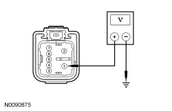
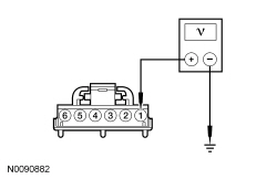
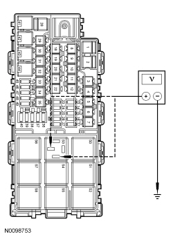
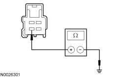
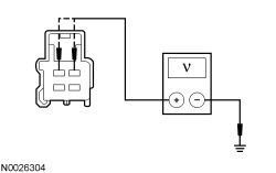
| D1 CHECK THE REAR WINDOW DEFROST GRID VOLTAGE | |
 | Yes
GO to D2 . No GO to D3 . |
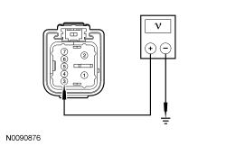
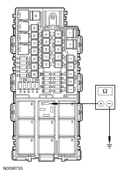
| D2 CHECK THE REAR WINDOW DEFROST GRID GROUND | |
 | Yes
CARRY OUT the Grid Wire Test in this section. REPAIR the rear window defrost grid or INSTALL a new rear window glass. REFER to Window Grid Wire Repair in this section. CLEAR the DTCs. TEST the system for normal operation. No REPAIR the circuit. TEST the system for normal operation. |
| D3 CHECK THE POWER TO THE RELAY | |
 | Yes
GO to D4 . No VERIFY Battery Junction Box (BJB) fuse 6 (30A) and SJB fuse 37 (10A) are OK. If OK, REPAIR the circuit(s). CLEAR the DTCs. TEST the system for normal operation. If not OK, REFER to the Wiring Diagrams manual to identify the possible causes of the circuit short. REPAIR the circuit. CLEAR the DTCs. TEST the system for normal operation. |
| D4 CHECK THE HVAC MODULE | |
 | Yes
GO to D5 . No GO to D6 . |
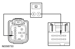
| D5 CHECK THE REAR WINDOW DEFROST RELAY | |
| Yes
REPAIR open in circuit CRD17 (GY). CLEAR the DTCs. TEST the system for normal operation. No INSTALL a new rear window defrost relay. CLEAR the DTCs. TEST the system for normal operation. |
| D6 CHECK THE REAR WINDOW DEFROST SWITCH (CC_SW_R_DEF) PID | |
| Yes
GO to D7 . No INSTALL a new FCIM . CLEAR the DTCs. TEST the system for normal operation. |
| D7 CHECK CIRCUIT CH122 (WH/OG) FOR AN OPEN | |
 | Yes
GO to D8 . No REPAIR the circuit. CLEAR the DTCs. TEST the system for normal operation. |
| D8 CHECK FOR CORRECT HVAC MODULE OPERATION | |
| Yes
INSTALL a new HVAC module. TEST the system for normal operation. No The system is operating correctly at this time. Concern may have been caused by a loose or corroded connector. CLEAR the DTCs. TEST the system for normal operation. |
Pinpoint Test E: The Defrost System Will Not Shut Off Automatically
Refer to Wiring Diagrams Cell 56 , Heated Window for schematic and connector information.
When the engine is running and the defrost switch (integral to the Front Controls Interface Module (FCIM)) is pressed, the FCIM sends the defrost request message to the HVAC module over the Controller Area Network (CAN). The HVAC module activates the rear window defrost relay by grounding the relay coil. When the rear window defrost relay is activated, power is supplied from the relay to the rear window defrost grid.
NOTICE: Use the correct probe adapter(s) when making measurements. Failure to use the correct probe adapter(s) may damage the connector.
| Test Step | Result / Action to Take |
|---|---|
| E1 CHECK REAR WINDOW DEFROST GRID POWER CIRCUIT FOR A SHORT TO VOLTAGE | |
| Yes
REPAIR circuit CRD17 (GY) for a short to voltage. CLEAR the DTCs. TEST the system for normal operation. No GO to E2 . |
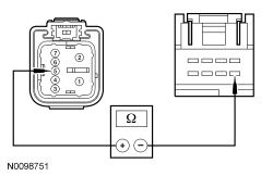
| E2 CHECK THE REAR WINDOW DEFROST RELAY | |
| Yes
GO to E3 . No INSTALL a new rear window defrost relay. CLEAR the DTCs. TEST the system for normal operation. |
| E3 CHECK CIRCUIT CH122 (WH/OG) FOR A SHORT TO GROUND | |
 | Yes
GO to E4 . No REPAIR short to ground in circuit CH122 (WH/OG). CLEAR the DTCs. TEST the system for normal operation. |
| E4 CHECK FOR CORRECT HVAC MODULE OPERATION | |
| Yes
INSTALL a new HVAC module. TEST the system for normal operation. No The system is operating correctly at this time. Concern may have been caused by a loose or corroded connector. CLEAR the DTCs. TEST the system for normal operation. |
Pinpoint Test F: The Short Drop Windows Do Not Operate Correctly
Refer to Wiring Diagrams Cell 100 , Power Windows for schematic and connector information.
The short drop window feature is activated when one (or both) of the doors are opened, which opens a door ajar switch. When the driver door is opened (opening the driver door ajar switch), a signal on circuit CPL26 (GN/VT) is interpreted by the driver window motor that the driver door is open. The driver window motor then carries out the short drop function on the driver window. When the passenger door is opened (opening the passenger door ajar switch), a signal on circuit CPL31 (WH) is interpreted by the passenger window motor that the passenger door is open. The passenger window motor then carries out the short drop function on the passenger window. This feature is on both the coupe and the convertible.
NOTICE: Use the correct probe adapter(s) when making measurements. Failure to use the correct probe adapter(s) may damage the connector.
| Test Step | Result / Action to Take |
|---|---|
| F1 VERIFY THE DOOR AJAR SWITCH OPERATION | |
| Yes
GO to F2 . No REFER to Section 417-02 to continue the diagnosis of the interior lamps. |
| F2 CARRY OUT THE WINDOW MOTOR INITIALIZATION | |
| Yes
The system is operating correctly at this time. INFORM the customer of the short drop window feature. REFER to the Owner's Literature. No For the driver window, GO to F3 . For the passenger window, GO to F4 . |
| F3 CHECK CIRCUIT CPL26 (GN/VT) FOR AN OPEN | |
 | Yes
INSTALL a new LH front window motor. REFER to Window Regulator Motor — Front Door in this section. TEST the system for normal operation. No REPAIR the circuit. TEST the system for normal operation. |
| F4 CHECK CIRCUIT CPL31 (WH) FOR AN OPEN | |
| Yes
INSTALL a new RH front window motor. REFER to Window Regulator and Motor — Front Door in this section. TEST the system for normal operation. No REPAIR the circuit. TEST the system for normal operation. |
Pinpoint Test G: The Convertible Top Drop Function is Inoperative/Does Not Operate Correctly
Refer to Wiring Diagrams Cell 100 , Power Windows for schematic and connector information.
The convertible top drop function is activated when the convertible top switch is operated. When the Body Control Module B (BCM-B) sees the voltage drop on circuit CPR23 (BU/OG) (lower) or CPR24 (GN/VT) (raise), the BCM-B first sends a signal to all 4 window motors on circuit CPW73 (GN/VT). At this time, all 4 window motors operate to the fully DOWN position. The rear window motors have a fully down sensor the BCM-B monitors through circuits CPW47 (VT/OG) and CPW53 (YE/OG). When the BCM-B sees that the LH and RH rear windows are fully down, it then grounds circuit CPR18 (WH/VT) (lower relay) or CPR19 (YE/BU) (raise relay) to activate the desired relay and operate the convertible top in the requested direction. If the BCM-B does not see the correct signal from the LH rear and RH rear window full down sensors, the BCM-B does not allow the convertible top to operate.
NOTICE: Use the correct probe adapter(s) when making measurements. Failure to use the correct probe adapter(s) may damage the connector.
| Test Step | Result / Action to Take |
|---|---|
| G1 VERIFY THE WINDOW OPERATION | |
| Yes
GO to G2 . No If the LH front window does not operate correctly, GO to Pinpoint Test A . If the RH front window does not operate correctly, GO to Pinpoint Test B . If one or both of the rear windows do not operate correctly, GO to Pinpoint Test C . |
| G2 OPERATE THE CONVERTIBLE TOP | |
| Yes
The system is operating correctly at this time. INFORM the customer of the convertible top drop function. REFER to the Owner's Literature. No If only the LH front window did not operate, GO to G3 . If only the RH front window did not operate, GO to G4 . If only the LH rear window did not operate, GO to G5 . If only the RH rear window did not operate, GO to G6 . If both the LH front and LH rear window did not operate, GO to G7 . If both the RH front and RH rear window did not operate, GO to G8 . If all windows did not operate, GO to G9 . |
| G3 CHECK CIRCUIT CPW73 (GN/VT) FOR AN OPEN | |
 | Yes
INSTALL a new LH front window motor. REFER to Window Regulator Motor — Front Door in this section. INITIALIZE the LH front window motor. REFER to Window Motor Initialization in this section. TEST the system for normal operation. No REPAIR the circuit. TEST the system for normal operation. |
| G4 CHECK CIRCUIT CPW73 (GN/VT) FOR AN OPEN | |
 | Yes
INSTALL a new RH front window motor. REFER to Window Regulator Motor — Front Door in this section. INITIALIZE the RH front window motor. REFER to Window Motor Initialization in this section. TEST the system for normal operation. No REPAIR the circuit. TEST the system for normal operation. |
| G5 CHECK CIRCUIT CPW73 (GN/VT) FOR AN OPEN | |
| Yes
INSTALL a new LH rear quarter window motor. REFER to Window Regulator and Motor — Rear Quarter in this section. TEST the system for normal operation. No REPAIR the circuit. TEST the system for normal operation. |
| G6 CHECK CIRCUIT CPW73 (GN/VT) FOR AN OPEN | |
| Yes
INSTALL a new RH rear quarter window motor. REFER to Window Regulator and Motor — Rear Quarter in this section. TEST the system for normal operation. No REPAIR the circuit. TEST the system for normal operation. |
| G7 CHECK CIRCUIT CPW73 (GN/VT) FOR AN OPEN | |
| Yes
GO to G11 . No REPAIR the circuit. TEST the system for normal operation. |
| G8 CHECK CIRCUIT CPW73 (GN/VT) FOR AN OPEN | |
| Yes
GO to G11 . No REPAIR the circuit. TEST the system for normal operation. |
| G9 CHECK CIRCUIT CPW73 (GN/VT) FOR A SHORT TO GROUND | |
 | Yes
GO to G10 . No REFER to the Wiring Diagrams manual to identify the possible causes of the circuit short. REPAIR the circuit. TEST the system for normal operation. |
| G10 CHECK CIRCUIT CPW73 (GN/VT) FOR A SHORT TO VOLTAGE | |
 | Yes
REFER to the Wiring Diagrams manual to identify the possible causes of the circuit short. REPAIR the circuit. TEST the system for normal operation. No GO to G11 . |
| G11 CHECK FOR CORRECT BCM-B OPERATION | |
| Yes
INSTALL a new BCM-B . REFER to Section 419-10 . TEST the system for normal operation. No The system is operating correctly at this time. The concern may have been caused by a loose or corroded connector. CLEAR the DTCs. REPEAT the self-test. |
Pinpoint Test H: The Delayed Accessory is Inoperative
The accessory delay relay is located in the Smart Junction Box (SJB). When the key is turned ON, the SJB activates the accessory delay relay by grounding the relay coil, and power is sent to all window motors and control switches. When the key is turned OFF, the SJB continues to ground the accessory delay relay coil for approximately 10 minutes, or until a door is opened.
NOTICE: Use the correct probe adapter(s) when making measurements. Failure to use the correct probe adapter(s) may damage the connector.
| Test Step | Result / Action to Take |
|---|---|
| H1 CHECK THE CORRECT OPERATION OF THE DOOR AJAR SWITCHES | |
| Yes
GO to H2 . No REFER to Section 417-02 to diagnose the interior lighting and door ajar switches. |
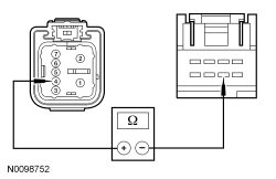
| H2 CHECK THE ACCESSORY DELAY RELAY | |
| Yes
VERIFY SJB fuse 41 (15A) is OK. If OK, GO to H3 . If not OK, REFER to the Wiring Diagrams manual to identify the possible causes of the circuit short. REPAIR the circuit. TEST the system for normal operation. No INSTALL a new accessory delay relay. TEST the system for normal operation. |
| H3 CHECK CIRCUIT CBP41 (BU) FOR AN OPEN | |
 | Yes
GO to H4 . No REPAIR the circuit. TEST the system for normal operation. |
| H4 CHECK FOR CORRECT SJB OPERATION | |
| Yes
INSTALL a new SJB . TEST the system for normal operation. No The system is operating correctly at this time. Concern may have been caused by a loose or corroded connector. CLEAR the DTCs. REPEAT the self-test. TEST the system for normal operation. |
Pinpoint Test I: The Delayed Accessory Does Not Turn Off
The accessory delay relay is located in the Smart Junction Box (SJB). When the key is turned ON, the SJB activates the accessory delay relay by grounding the relay coil, and power is sent to all window motors and control switches. When the key is turned OFF, the SJB continues to ground the accessory delay relay coil for approximately 10 minutes, or until a door is opened.
NOTICE: Use the correct probe adapter(s) when making measurements. Failure to use the correct probe adapter(s) may damage the connector.
| Test Step | Result / Action to Take |
|---|---|
| I1 CHECK FOR STUCK/STICKING ACCESSORY DELAY RELAY | |
| Yes
GO to I3 . No GO to I2 . |
| I2 CHECK THE ACCESSORY DELAY RELAY | |
| Yes
GO to I4 . No INSTALL a new accessory delay relay. TEST the system for normal operation. |
| I3 CHECK CIRCUIT CBP41 (BU) FOR AN OPEN | |
 | Yes
REPAIR the circuit. TEST the system for normal operation. No GO to I4 . |
| I4 CHECK FOR CORRECT SJB OPERATION | |
| Yes
INSTALL a new SJB . TEST the system for normal operation. No The system is operating correctly at this time. Concern may have been caused by a loose or corroded connector. CLEAR the DTCs. REPEAT the self-test. TEST the system for normal operation. |
Pinpoint Test J: DTCs B126D:15 or B1269:11
Refer to Wiring Diagrams Cell 103 , Convertible Top for schematic and connector information.
Refer to Wiring Diagrams Cell 100 , Power Windows for schematic and connector information.
The Body Control Module B (BCM-B) monitors the status of the convertible top through circuits CPR92 (BU/GY) and CPR93 (YE/GY). When the convertible top is in the full UP position, the convertible top ajar switch closes and provides ground to circuit CPR92 (BU/GY). When the convertible top is in the full DOWN position, the convertible top ajar switch closes and provides ground to circuit CPR93 (YE/GY). Ground is provided to the convertible top ajar switch through circuit GD110 (BK/WH). DTC B126D:15 sets if the convertible top ajar switch on-demand self test is run with the convertible top not in the full DOWN position. DTC B1269:11 sets if the convertible top ajar switch on-demand self test is run with the convertible top in the full UP position. If DTC B126D:15 or B1269:11 is present, the rear quarter windows may still function during convertible top operation, but will not function when commanded by the window control switch.
NOTICE: Use the correct probe adapter(s) when making measurements. Failure to use the correct probe adapter(s) may damage the connector.
| Test Step | Result / Action to Take | |||||||||
|---|---|---|---|---|---|---|---|---|---|---|
| J1 CARRY OUT THE ON-DEMAND SELF TEST FOR THE CONVERTIBLE TOP AJAR SWITCH | ||||||||||
NOTE: False DTCs will set if the convertible top is not in the full DOWN position before carrying out this test. | Yes
GO to J2 . No The concern is not present at this time. RETURN the vehicle to the customer. | |||||||||
| J2 CHECK THE CONVERTIBLE TOP AJAR SWITCH OPERATION | ||||||||||
 | Yes
GO to J3 . No INSTALL a new convertible top ajar switch. REFER to Section 501-18 . CLEAR the DTCs. REPEAT the self-test. | |||||||||
| J3 CHECK CIRCUIT GD110 (BK/WH) FOR AN OPEN | ||||||||||
 | Yes
GO to J4 . No REPAIR the circuit. CLEAR the DTCs. REPEAT the self-test. | |||||||||
| J4 CHECK CIRCUITS CPR93 (YE/GY) AND CPR92 (BU/GY) FOR A SHORT TO VOLTAGE | ||||||||||
 | Yes
REPAIR the circuit. CLEAR the DTCs. REPEAT the self-test. No GO to J5 . | |||||||||
| J5 CHECK CIRCUITS CPR93 (YE/GY) AND CPR92 (BU/GY) FOR A SHORT TO GROUND | ||||||||||
 | Yes
GO to J6 . No REPAIR the circuit. CLEAR the DTCs. REPEAT the self-test. | |||||||||
| J6 CHECK CIRCUITS CPR93 (YE/GY) AND CPR92 (BU/GY) FOR AN OPEN | ||||||||||
 | Yes
GO to J7 . No REPAIR the circuit. CLEAR the DTCs. REPEAT the self-test. | |||||||||
| J7 CHECK FOR CORRECT BCM-B OPERATION | ||||||||||
| Yes
INSTALL a new BCM-B . REFER to Section 419-10 . TEST the system for normal operation. No The system is operating correctly at this time. The concern may have been caused by a loose or corroded connector. CLEAR the DTCs. REPEAT the self-test. |
Pinpoint Test K: The One-Touch Up/Down Feature is Inoperative
Refer to Wiring Diagrams Cell 100 , Power Windows for schematic and connector information.
During normal operation, when the window control switch is pressed to the second detent position to request an auto up or auto down operation, the window control switch provides a 12-volt signal on both the up and down line simultaneously. During an auto up or auto down request, the window motor determines intended window direction by the signal first received (first detent position). If the window control switch is pressed too quickly to the second detent position (less than 5 milliseconds of time between first detent signal and second detent signal), the window motor will not be able to determine the intended direction request and will not operate until the window control switch is released and pressed again.
| Test Step | Result / Action to Take |
|---|---|
| K1 DE-INITIALIZE, THEN INITIALIZE THE DOOR WINDOW MOTOR | |
| Yes
The system is operating normally at this time. The window motor lost initialization. No GO to K2 . |
| K2 CHECK THE SUSPECT WINDOW CONTROL SWITCH | |
| Yes
INSTALL a new LH or RH front window motor. REFER to Window Regulator Motor — Front Door in this section. INITIALIZE the front window motor. REFER to Window Motor Initialization in this section. TEST the system for normal operation. No INSTALL a new LH or RH window control switch. REFER to Window Control Switch in this section. TEST the system for normal operation. |
Component Tests
Grid Wire Test