Diagnostics in this manual assume a certain skill level and knowledge of Ford-specific diagnostic practices. Refer to Diagnostic Methods in
Section 100-00
for information about these practices.
Diagnostics in this manual assume a certain skill level and knowledge of Ford-specific diagnostic practices. Refer to Diagnostic Methods in
Section 100-00
for information about these practices.
In most circumstances, the PCM sets DTCs to help guide with diagnostics. Refer to the DTC Chart before using the symptom chart. The Condition column lists the vehicle condition. The Source column lists a detailed vehicle condition. The Action column lists the action to be performed to determine the cause of the condition. Each action lists the components that can caused the system and the individual components in that system. The components are listed in order of disassembly. Use the list of components and the required action to focus on disassembly inspections for the root cause of the concern.
Symptom Chart
| Condition
| Possible Sources
| Action
|
|---|
- The
system does not release/lock correctly
| - Refer to Diagnostic Routine
- damaged
- Selector lever cable
| |
- The selector lever is out of correct gear relationship
| - Selector lever cable and bracket installation
- Selector lever cable out of adjustment
| |
- Excessive selector lever effort
| | |
| - Selector cable and bracket installation
| |
- Selector lever will not shift
| | |
| - Broken selector level cable
| |
- Vibration — a high frequency (20-80 Hz) that is felt through the seat or selector lever. Changes with engine speed
| - Selector lever cable incorrectly routed, grounded out or loose
| |
Diagnostics in this manual assume a certain skill level and knowledge of Ford-specific diagnostic practices. Refer to Diagnostic Methods in
Section 100-00
for information about these practices.
The
system is controlled by the
and is activated when the
receives a brake pedal applied input.
| Test Step
| Result / Action to Take
|
|---|
|
A1 RETRIEVE AND RECORD ALL DTCS
|
|
- Ignition ON.
- Using a scan tool, retrieve DTCs.
- Was DTC B2572 set?
| Yes
GO to
A2
.
No
The issue may not be the
system. GO to
Symptom Chart
.
|
|
A2 CHECK THE
POWER CIRCUIT FOR AN OPEN
|
|
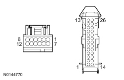
- Disconnect: Transmission Shift Selector C307.
- Inspect for damaged or pushed-out terminals.
- Apply and release the brake pedal.
- Measure the
voltage
between.
| Positive Lead
| Negative Lead
| | Pin
| Circuit
| Pin
| Circuit
| | C307-1
| CET53 (BU/OG)
| —
| Ground
|
 - Is the voltage greater than 10 volts with the brake pedal applied and 0 volt with the brake pedal released?
| Yes
GO to
A3
.
No
GO to
A4
.
|
|
A3 CHECK THE
GROUND CIRCUIT FOR AN OPEN
|
|
- Measure the
resistance
between.
| Positive Lead
| Negative Lead
| | Pin
| Circuit
| Pin
| Circuit
| | C307-5
| GD139 (BK/YE)
| —
| Ground
|
- Is the resistance less than 5 ohms?
| Yes
INSTALL a new selector lever assembly. REFER to
Selector Lever
.
No
REPAIR the circuit.
|
|
A4 CHECK THE
POWER CIRCUIT FOR AN OPEN
|
|
- Ignition OFF.
- Disconnect:
C2280C.
- Inspect for damaged or pushed-out terminals.
- Measure the
resistance
between.
| Positive Lead
| Negative Lead
| | Pin
| Circuit
| Pin
| Circuit
| | C307-1
| CET53 (BU/OG)
| C2280C-23
| CET53 (BU/OG)
|
 - Is the resistance less than 5 ohms?
| Yes
GO to
A5
.
No
REPAIR the circuit.
|
|
A5 CHECK THE
POWER CIRCUIT FOR A SHORT TO GROUND
|
|
- Measure the
resistance
between.
| Positive Lead
| Negative Lead
| | Pin
| Circuit
| Pin
| Circuit
| | C307-1
| CET53 (BU/OG)
| —
| Ground
|
- Is the resistance greater than 10,000 ohms?
| Yes
GO to
A6
.
No
REPAIR the circuit.
|
|
A6 CHECK THE
POWER CIRCUIT FOR A SHORT VOLTAGE
|
|
- Ignition ON.
- Measure the
voltage
between.
| Positive Lead
| Negative Lead
| | Pin
| Circuit
| Pin
| Circuit
| | C307-1
| CET53 (BU/OG)
| —
| Ground
|
- Is any voltage present?
| Yes
REPAIR the circuit.
No
INSTALL a new selector lever. REFER to
Selector Lever
.
|
Diagnostics in this manual assume a certain skill level and knowledge of Ford-specific diagnostic practices. Refer to Diagnostic Methods in
Section 100-00
for information about these practices.
The SelectShift™ switch is a toggle switch integral to the selector lever knob. When the selector lever is placed in the sport mode position, the upshift/downshift feature becomes activated. If a new switch is required install a new selector lever knob.
| Test Step
| Result / Action to Take
|
|---|
|
B1 RETRIEVE AND RECORD ALL DTCS
|
|
- Ignition ON.
- Using a scan tool, retrieve DTCs.
- Is DTC P0815 set?
| Yes
CLEAR the DTC. PERFORM the
self-test. If DTC P0815 returns, GO to
B2
.
No
CLEAR the DTC. PERFORM the
self-test. If DTC P0816 returns, GO to
B7
.
|
|
B2 CHECK THE UPSHIFT SIGNAL CIRCUIT FOR VOLTAGE
|
|
- Ignition OFF.
- Disconnect: Transmission Shift Selector C307.
- Inspect for damaged or pushed-out terminals.
- Ignition ON.
- Measure the
voltage
between.
| Positive Lead
| Negative Lead
| | Pin
| Circuit
| Pin
| Circuit
| | C307-9
| CET35 (BN)
| —
| Ground
|
- Is the voltage greater that 10 volts?
| Yes
GO to
B5
.
No
GO to
B3
.
|
|
B3 CHECK THE UPSHIFT SIGNAL CIRCUIT FOR AN OPEN
|
|
- Ignition OFF.
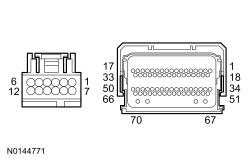
- Disconnect: PCM C175B (5.0L).
- Disconnect: PCM C1381B (3.7L
).
- Inspect for damaged or pushed-out terminals.
- Measure the
resistance
between.
| Positive Lead
| Negative Lead
| | Pin
| Circuit
| Pin
| Circuit
| | C307-9
| CET35 (BN)
| C175B-23
| CET35 (BN)
|
 - Measure the
resistance
between.
| Positive Lead
| Negative Lead
| | Pin
| Circuit
| Pin
| Circuit
| | C307-9
| CET35 (BN)
| C1381B-23
| CET35 (BN)
|
- Is the resistance less than 5 ohms?
| Yes
GO to
B4
.
No
REPAIR the circuit.
|
|
B4 CHECK THE UPSHIFT SIGNAL CIRCUIT FOR A SHORT TO GROUND
|
|
- Measure the
resistance
between.
| Positive Lead
| Negative Lead
| | Pin
| Circuit
| Pin
| Circuit
| | C307-9
| CET35 (BN)
| —
| Ground
|
- Is the resistance greater than 10,000 ohms?
| Yes
INSTALL a new PCM. REFER to
Section 303-14
. PROGRAM the PCM with the latest calibration level. PERFORM the Solenoid Body Strategy Data Download procedure. REFER to Solenoid Body Strategy in
Section 307-01
.
No
REPAIR the circuit.
|
|
B5 CHECK THE SIGNAL RETURN CIRCUIT FOR AN OPEN
|
|
- Measure the
voltage
between.
| Positive Lead
| Negative Lead
| | Pin
| Circuit
| Pin
| Circuit
| | C307-9
| CET35 (BN)
| C307-11
| RE405 (GN/WH)
|
- Is voltage greater than 10 volts?
| Yes
GO to
B6
.
No
REPAIR the circuit. If no open is found, INSTALL a new PCM. REFER to
Section 303-14
. PROGRAM the PCM with the latest calibration level. PERFORM the Solenoid Body Strategy Data Download procedure. REFER to Solenoid Body Strategy in
Section 307-01
.
|
|
B6 CHECK THE SELECTSHIFT™ SWITCH
|
|
- Disconnect: SelectShift™ Switch from the Selector Lever Assembly.
- Measure the
component side resistance
while cycling the SelectShift™ upshift switch.
| Positive Lead
| Negative Lead
| | Pin
| Circuit
| Pin
| Circuit
| | 9
| —
| 11
| —
|
- Is the resistance less than 1.5 ohms when applied and greater than 10,000 ohms when released?
| Yes
INSTALL a new selector lever. REFER to
Selector Lever
.
No
INSTALL a new SelectShift™ switch. REFER to
Selector Lever Knob
.
|
|
B7 CHECK THE DOWNSHIFT SIGNAL CIRCUIT FOR VOLTAGE
|
|
- Ignition OFF.
- Disconnect: Transmission Shift Selector C307.
- Inspect for damaged or pushed-out terminals.
- Ignition ON.
- Measure the
voltage
between.
| Positive Lead
| Negative Lead
| | Pin
| Circuit
| Pin
| Circuit
| | C307-10
| CET42 (GN/VT)
| —
| Ground
|
- Is the voltage greater that 10 volts?
| Yes
GO to
B10
.
No
GO to
B8
.
|
|
B8 CHECK THE DOWNSHIFT SIGNAL CIRCUIT FOR AN OPEN
|
|
- Ignition OFF.
- Disconnect: PCM C175B (5.0L).
- Disconnect: PCM C1381B (3.7L
).
- Inspect for damaged or pushed-out terminals.
- Measure the
resistance
between.
| Positive Lead
| Negative Lead
| | Pin
| Circuit
| Pin
| Circuit
| | C307-10
| CET42 (GN/VT)
| C175B-24
| CET42 (GN/VT)
|
- Measure the
resistance
between.
| Positive Lead
| Negative Lead
| | Pin
| Circuit
| Pin
| Circuit
| | C307-10
| CET42 (GN/VT)
| C1381B-24
| CET42 (GN/VT)
|
- Is the resistance less than 5 ohms?
| Yes
GO to
B9
.
No
REPAIR the circuit.
|
|
B9 CHECK THE DOWNSHIFT SIGNAL CIRCUIT FOR A SHORT TO GROUND
|
|
- Measure the
resistance
between.
| Positive Lead
| Negative Lead
| | Pin
| Circuit
| Pin
| Circuit
| | C307-10
| CET42 (GN/VT)
| —
| Ground
|
- Is the resistance greater than 10,000 ohms?
| Yes
INSTALL a new PCM. REFER to
Section 303-14
. PROGRAM the PCM. with the latest calibration level. PERFORM the Solenoid Body Strategy Data Download procedure. REFER to Solenoid Body Strategy in
Section 307-01
.
No
REPAIR the circuit.
|
|
B10 CHECK THE SIGNAL RETURN CIRCUIT FOR AN OPEN
|
|
- Measure the
voltage
between.
| Positive Lead
| Negative Lead
| | Pin
| Circuit
| Pin
| Circuit
| | C307-10
| CET42 (GN/VT)
| C307-11
| RE405 (GN/WH)
|
- Is voltage greater than 10 volts?
| Yes
GO to
B11
.
No
REPAIR the circuit. If no open is found, INSTALL a new PCM. REFER to
Section 303-14
. PROGRAM the PCM with the latest calibration level. PERFORM the Solenoid Body Strategy Data Download procedure. REFER to Solenoid Body Strategy in
Section 307-01
.
|
|
B11 CHECK THE SELECTSHIFT™ SWITCH
|
|
- Disconnect: SelectShift™ Switch from the Selector Lever Assembly.
- Measure the
component side resistance
while cycling the SelectShift™ downshift switch.
| Positive Lead
| Negative Lead
| | Pin
| Circuit
| Pin
| Circuit
| | 10
| —
| 11
| —
|
- Is the resistance less than 1.5 ohms when applied and greater than 10,000 ohms when released?
| Yes
INSTALL a new selector lever. REFER to
Selector Lever
.
No
INSTALL a new SelectShift™ switch. REFER to
Selector Lever Knob
.
|