SECTION 308-02: Clutch Controls
| 2014 Mustang Workshop Manual
|
DIAGNOSIS AND TESTING
| Procedure revision date: 02/06/2013
|
Clutch Controls
Inspection and Verification
NOTICE:
If transmission noise is reported, first check the transmission fluid level. The vehicle should not be driven if the transmission fluid level is low. A low transmission fluid level will damage the transmission.
NOTE:
Before attempting to repair any concerns, road test the vehicle to determine which system the concern is in.
NOTE:
If an observed or reported concern is found, correct the cause before proceeding.
Gear driven units produce a certain level of noise. Some noise is acceptable and audible at certain speeds or under various driving conditions. Many conditions, such as road and weather can amplify normal vehicle noise.
The following overview is a guide to diagnose a transmission or clutch concern:
- Verify and document the customer concern.
- During the customer interview, if a leak was noticed or if a leak is the concern, check the transmission fluid level. The vehicle should not be driven if the transmission fluid level is low.
- Check fluid level and condition.
- Evaluate the clutch hydraulic system.
- Evaluate the clutch.
- Inspect gearshift mechanism.
- Evaluate the transmission.
- Find the cause of the problem and correct it.
Check Fluid Level and Condition
NOTICE:
The vehicle should not be driven if the transmission fluid level is low or damage may occur.
NOTICE:
Excessive temperatures may break down the transmission lubricant. If there is reason to believe the transmission has been subjected to temperatures exceeding 135°C (275°F) for an extended period (greater than 20 minutes), change the lubricant immediately.
An incorrect transmission fluid level may affect the transmission operation and can result in transmission damage. For transmission draining and filling, refer to
Section 308-03A
or
Section 308-03B
.
A low transmission fluid level can result in poor transmission shifting, engagement or damage. It also indicates a leak in the transmission seals or gaskets.
- Check the transmission fluid condition.
- Allow the transmission fluid to drip onto a white cloth and examine the stain. Check the transmission fluid for contamination or metal particles.
Evaluate Clutch Hydraulic System
- Verify the clutch hydraulic fluid reservoir is filled to the correct level.
- If the clutch hydraulic fluid level is correct, proceed to clutch check.
- If the clutch hydraulic fluid level is low, add fluid as necessary. Check the clutch hydraulic system for leaks and repair as necessary.
Evaluate the Clutch
- Apply and release the clutch pedal slowly to check pedal binding. Make sure the clutch pedal can be fully applied and is not restricted by the floor mat.
- Measure the clutch reserve.
GO to Pinpoint Test C
.
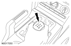
- With the engine idling and the park brake applied, move the gearshift lever into 4th gear. Increase engine speed to 2,000 rpm and slowly release the clutch pedal.
- If the engine stalls, the clutch is OK.
- If the engine does not stall, the clutch is slipping. Repair as necessary.
- Compare the clutch evaluation results with the following chart. The following list of conditions are typical clutch concerns.
Symptom Chart — Clutch Controls
Diagnostics in this manual assume a certain skill level and knowledge of Ford-specific diagnostic practices. Refer to Diagnostic Methods in
Section 100-00
for information about these practices.
Symptom Chart — Clutch Operation
| Condition
| Possible Sources
| Action
|
|---|
- Clutch pedal feels spongy or has excessive travel. Clutch will not disengage
| - Insufficient clutch fluid
- Air in hydraulic system
- Clutch pedal reserve
- Diaphragm springs
- Clutch disc
- Clutch disc splines
- Oil on clutch facing
| |
- Clutch drag, also hard to shift
| - Insufficient clutch fluid
- Air in hydraulic system
- Clutch pedal reserve
- Diaphragm springs
- Clutch disc
- Transmission concern
| |
| - Clutch pedal reserve
- Clutch slave cylinder
- Pilot bearing
- Excessive crankshaft end play
| |
| - Clutch master cylinder
- Clutch slave cylinder
- Clutch hydraulic tubes
| |
Inspect Gearshift Mechanism
- Inspect the gearshift mechanism for:
- missing or loose fasteners.
- Repair as necessary.
Evaluate Transmission
- Road test the vehicle. Use the following methods to diagnose the concern.
- Evaluate the noise in NEUTRAL while vehicle is parked.
- Check whether the noise is present with the clutch fully disengaged (clutch pedal applied). Check to see if the pedal pulsates abnormally (clutch diaphragm finger runout).
- Check whether the noise is present with the gearshift in the NEUTRAL position and the clutch fully engaged (clutch pedal released). Apply the park brake and move the gearshift towards the 1st gear position. Apply very slight pressure and note if the gear noise level is reduced (gear rollover noise).
- With the clutch fully engaged (clutch pedal released) check whether the noise is present as the engine speed is raised. If the noise reduces, note the engine speed at which this occurs.
- Listen for any change in noise while applying and releasing the clutch pedal.
- Listen for any change in noise while changing the engine rpm.
- Drive the vehicle and shift through all the gears including REVERSE. Listen for any changes in noise.
- Drive the vehicle in the gear in which the noise is most noticeable. Apply the clutch pedal and leave the gear engaged. Listen for any change in noise.
- Drive the vehicle in the gear in which the noise is most noticeable. Apply the clutch pedal and shift the transmission into NEUTRAL. Release the clutch pedal and allow the vehicle to coast.
- Compare the noise to another vehicle. Make sure the transmissions are the same.
- Compare the road test results with the following symptom charts. The following list of conditions are typical transmission concerns:
GO to Symptom Charts.
Section 308-03A
, or GO to Symptom Charts
Section 308-03B
.
Pinpoint Tests
Pinpoint Test A: Clutch Pedal Feels Spongy or Has Excessive Travel/Clutch Will Not Disengage/Clutch System Leakage
Diagnostic Overview
Diagnostics in this manual assume a certain skill level and knowledge of Ford-specific diagnostic practices. Refer to Diagnostic Methods in
Section 100-00
for information about these practices.
Normal Operation and Fault Conditions
The clutch is designed to transfer the power from the engine to the transmission, which may be stationary (starting) or rotating at a different speed (upshifting or downshifting). The clutch is functioning correctly when the engine and transmission are rotating at the same speed with the clutch engaged. Clutch pedal movement is transmitted by fluid pressure, which actuates the clutch release hub and bearing. The clutch release hub and bearing pushes on the spring center towards the flywheel. The diaphragm spring pivots at the fulcrum, relieving the load on the clutch pressure plate. Steel spring straps riveted in the clutch pressure plate cover pull the clutch pressure plate from the clutch disc, disengaging the engine torque from the transmission.
This pinpoint test is intended to diagnose the following:
- Internal operation
- Clutch pedal reserve
- Clutch slave cylinder travel
- Clutch disc
- Clutch pressure plate
- Clutch pedal free play
PINPOINT TEST A: CLUTCH PEDAL FEELS SPONGY OR HAS EXCESSIVE TRAVEL/CLUTCH WILL NOT DISENGAGE/CLUTCH SYSTEM LEAKAGE
| Test Step
| Result / Action to Take
|
|---|
|
A1 CHECK THE FLUID LEVEL
|
|
- NOTE:
Do not check the hydraulic system after a road test. Allow the vehicle to cool down before carrying out the clutch hydraulic system check.
- Remove the brake and clutch reservoir cap.
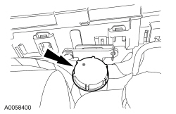 - Check the fluid level of the brake and clutch reservoir.
- Is the fluid level at or above the step mark?
| Yes
INSTALL the reservoir cap. GO to
A2
.
No
ADD brake fluid to the specified level. GO to
A2
.
|
|
A2 INSPECT THE HYDRAULIC SYSTEM FOR LEAKAGE
|
|
- Check the reservoir and reservoir tubes for leakage.
- Check the master cylinder and hydraulic tube for leakage.
- Check the clutch slave cylinder and the hydraulic tube connection for leakage.
- Are there any signs of leakage?
| Yes
INSTALL new components as necessary.
No
GO to
A3
.
|
|
A3 CHECK INTERNAL OPERATION
|
|
- Remove the reservoir cap.
- Have an assistant slowly apply and release the clutch pedal.
- On the down stroke, the fluid level should not increase by more than 1 mm (0.039 in).
- Does the fluid level increase more than 1 mm (0.039 in)?
| Yes
INSTALL a new clutch master cylinder assembly. REFER to
Clutch Master Cylinder
.
No
GO to
A4
.
|
|
A4 CHECK THE CLUTCH PEDAL RESERVE
|
|
| Yes
The clutch hydraulic system is OK.
No
GO to
A5
.
|
|
A5 CHECK THE CLUTCH PRESSURE PLATE
|
|
- Remove the clutch pressure plate. REFER to
Section 308-01
.
- Inspect the clutch pressure plate for wear or runout. REFER to
Section 308-01
.
- Are there any signs of excessive wear or runout to the clutch pressure plate?
| Yes
INSTALL a new clutch pressure plate. REFER to
Section 308-01
.
No
GO to
A6
.
|
|
A6 INSPECT THE CLUTCH DISC
|
|
- Carry out the clutch disc inspection procedure. REFER to
Section 308-01
.
- Is the clutch disc OK?
| Yes
GO to
A7
.
No
INSTALL a new clutch disc. REFER to
Section 308-01
.
|
|
A7 CHECK CLUTCH PEDAL FREE PLAY
|
|
NOTE:
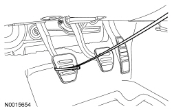
The clutch pedal free play is the distance between the clutch pedal when fully released and the position when slight resistance is felt on downward motion.
- Ignition OFF.
- Attach a tape measure to the cable tie.
- While observing the tape measure, slowly push downward on the clutch pedal until a slight resistance is felt.
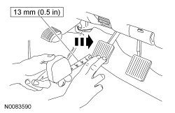 - Is the clutch pedal free play less than 13 mm (0.511 in) ?
| Yes
The clutch hydraulic system is OK.
No
BLEED the clutch hydraulic system. REFER to
Clutch System Bleeding
.
|
Pinpoint Test B: Clutch Drag, Also Hard to Shift
Diagnostic Overview
Diagnostics in this manual assume a certain skill level and knowledge of Ford-specific diagnostic practices. Refer to Diagnostic Methods in
Section 100-00
for information about these practices.
Normal Operation and Fault Conditions
The clutch is designed to transfer the power from the engine to the transmission, which may be stationary (starting) or rotating at a different speed (upshifting or downshifting). The clutch is functioning correctly when the engine and transmission are rotating at the same speed with the clutch engaged. Clutch pedal movement is transmitted by fluid pressure, which actuates the clutch release hub and bearing. The clutch release hub and bearing pushes on the spring center towards the flywheel. The diaphragm spring pivots at the fulcrum, relieving the load on the clutch pressure plate. Steel spring straps riveted in the clutch pressure plate cover pull the clutch pressure plate from the clutch disc, disengaging the engine torque from the transmission.
This pinpoint test is intended to diagnose the following:
- Internal operation
- Clutch pedal reserve
- Clutch slave cylinder travel
- Clutch disc
- Clutch pressure plate
- Clutch pedal free play
PINPOINT TEST B: CLUTCH DRAG, ALSO HARD TO SHIFT
| Test Step
| Result / Action to Take
|
|---|
|
B1 CHECK FLUID LEVEL
|
|
- Ignition OFF.
- Remove the reservoir cap.
- Inspect the fluid level in the brake and clutch reservoir.
- Is the fluid level at or above the step mark?
| Yes
INSTALL the reservoir cap. GO to
B2
.
No
ADD brake fluid. GO to
B2
and CHECK for leaks.
|
|
B2 INSPECT THE CLUTCH HYDRAULIC SYSTEM FOR LEAKAGE
|
|
- Inspect the clutch master cylinder and the hydraulic tubes for leakage.
- Inspect the reservoir and reservoir tube for leakage.
- Inspect the clutch slave cylinder and the hydraulic tube connection for leakage.
- Are there any signs of leakage?
| Yes
INSTALL new components as necessary.
No
GO to
B3
.
|
|
B3 CHECK INTERNAL OPERATION
|
|
- Remove the reservoir cap.
- Have an assistant slowly apply and release the clutch pedal.
- On the down stroke, the fluid level should not increase by more than 1 mm (0.039 in).
- Does the fluid level increase more than 1 mm (0.039 in)?
| Yes
INSTALL a new clutch master cylinder assembly. REFER to
Clutch Master Cylinder
.
No
GO to
B4
.
|
|
B4 CHECK THE CLUTCH PEDAL RESERVE
|
|
| Yes
The clutch hydraulic system is OK.
No
GO to
B5
.
|
|
B5 CHECK THE CLUTCH PEDAL FREE PLAY
|
|
NOTE:
The clutch pedal free play is the distance between the clutch pedal when fully released and the position when slight resistance is felt on downward motion.
- Ignition OFF.
- Attach a tape measure to the cable tie.
- While observing the tape measure, slowly push downward on the clutch pedal until a slight resistance is felt.
- Is the clutch pedal free play less than 13 mm (0.511 in) ?
| Yes
The clutch hydraulic system is OK.
No
GO to
B6
.
|
|
B6 CHECK THE CLUTCH PRESSURE PLATE
|
|
- Remove the clutch pressure plate. REFER to
Section 308-01
.
- Inspect the clutch pressure plate for wear or runout. REFER to
Section 308-01
.
- Are there any signs of excessive wear or runout to the clutch pressure plate?
| Yes
INSTALL a new clutch pressure plate. REFER to
Section 308-01
.
No
GO to
B7
.
|
|
B7 INSPECT THE CLUTCH DISC
|
|
- Carry out the clutch disc inspection procedure. REFER to
Section 308-01
.
- Is the clutch disc OK?
| Yes
GO to
B8
.
No
INSTALL a new clutch disc. REFER to
Section 308-01
.
|
|
B8 INSPECT THE TRANSMISSION
|
|
- Remove the transmission. REFER to
Section 308-03A
or
Section 308-03B
.
- Disassemble the transmission. REFER to
Section 308-03A
or
Section 308-03B
.
- Carry out the following:
- Inspect all the shift rails for excessive scuffing or wear.
- Check the interlock pins on the shift rail.
- Inspect the shift pads for wear or cracking.
- Inspect the shift forks for wear or damage.
- Check the synchronizer rings of the affected gear for wear or damage.
- Check the synchronizer hubs of the affected gear for wear or damage.
- Inspect the clutching teeth of the affected gear.
- Are there any internal components worn or damaged?
| Yes
INSTALL new components or REPAIR as necessary. REFER to
Section 308-03A
or
Section 308-03B
.
No
ASSEMBLE and INSTALL the transmission. REFER to
Section 308-03A
or
Section 308-03B
.
|
Pinpoint Test G: Excessive Noise
Diagnostic Overview
Diagnostics in this manual assume a certain skill level and knowledge of Ford-specific diagnostic practices. Refer to Diagnostic Methods in
Section 100-00
for information about these practices.
Normal Operation and Fault Conditions
The clutch is designed to transfer the power from the engine to the transmission, which may be stationary (starting) or rotating at a different speed (upshifting or downshifting). The clutch is functioning correctly when the engine and transmission are rotating at the same speed with the clutch engaged. Clutch pedal movement is transmitted by fluid pressure, which actuates the clutch release hub and bearing. The clutch release hub and bearing pushes on the spring center towards the flywheel. The diaphragm spring pivots at the fulcrum, relieving the load on the clutch pressure plate. Steel spring straps riveted in the clutch pressure plate cover pull the clutch pressure plate from the clutch disc, disengaging the engine torque from the transmission.
This pinpoint test is intended to diagnose the following:
- Transmission
- Clutch slave cylinder
- Pilot bearing
PINPOINT TEST C: EXCESSIVE NOISE
| Test Step
| Result / Action to Take
|
|---|
|
C1 TRANSMISSION NEUTRAL GEAR ROLLOVER TEST
|
|
- Start the engine.
- With the engine at idle, the transmission in NEUTRAL and the clutch engaged (pedal up). If noise is excessive, apply the clutch pedal to stop the transmission input shaft from rotating.
- Does the noise stop when the clutch pedal is applied?
| Yes
INSPECT the clutch components for damage. REFER to
Section 308-01
.
No
GO to
C2
.
|
|
C2 CHECK THE CLUTCH SYSTEM
|
|
- Ignition OFF.
- Using slow, medium, then fast strokes, apply and release the clutch pedal.
- Is there a squeak?
| Yes
GO to
C3
.
No
The clutch system is OK. VERIFY the customer concern.
|
|
C3 CHECK THE
SWITCH
|
|
- Remove the
switch. Using slow, medium, then fast strokes, apply and release the clutch pedal.
- Is there a squeak?
| Yes
REINSTALL the
switch. GO to
C4
.
No
INSTALL a new
switch.
|
|
C4 CHECK THE CLUTCH SLAVE CYLINDER
|
|
- Remove the transmission. REFER to
Section 308-03A
or
Section 308-03B
.
- Inspect the clutch slave cylinder for wear or loss of lubrication.
- Are there any signs of wear or loss of lubrication?
| Yes
INSTALL a new clutch slave cylinder. REFER to
Clutch Slave Cylinder
.
No
GO to
C5
.
|
|
C5 CHECK THE PILOT BEARING
|
|
- Inspect the pilot bearing for wear or damage. REFER to
Section 308-01
.
- Is the pilot bearing OK?
| Yes
GO to
C6
.
No
INSTALL a new pilot bearing. REFER to
Section 308-01
.
|
|
C6 CHECK THE DAMPER SPRINGS
|
|
- Inspect the damper springs for fatigue or breakage. REFER to
Section 308-01
.
- Are there any signs of fatigue or breakage?
| Yes
INSTALL a new clutch disc. REFER to
Section 308-01
.
No
INSPECT the crankshaft end play. For 3.7L
engines, REFER to
Section 303-01A
. For 5.0L (4V) engines, REFER to
Section 303-01B
. For 5.8L (4V) engines, REFER to
Section 303-01C
.
|