
FLU77-4 or equivalent

014-R1063 or equivalent


NUD105-R025D or equivalent
SECTION 413-01: Instrumentation, Message Center, and Warning Chimes
| 2014 Mustang Workshop Manual
|
DIAGNOSIS AND TESTING
| Procedure revision date: 01/07/2013
|
| Fluke 77-1V Digital Multimeter
FLU77-4 or equivalent |
| Instrument Gauge System Tester
014-R1063 or equivalent |
| Vehicle Communication Module (VCM) and Integrated Diagnostic System (IDS) software with appropriate hardware, or equivalent scan tool
|
| Flex Probe Kit
NUD105-R025D or equivalent |
Principles of Operation
NOTE: When installing a new Instrument Panel Cluster (IPC), it is necessary to upload the module configuration to the scan tool. Following installation of the IPC , download the module configuration from the scan tool into the new IPC . Refer to Section 418-01 to carry out Programmable Module Installation (PMI). It is also necessary to carry out a parameter reset procedure whenever a new IPC or PCM is installed. Refer to Section 419-01B .
The IPC , message center and warning chimes utilize a microprocessor to control the gauge and indicator functions. Data is sent to the IPC over the Medium Speed Controller Area Network (MS-CAN) and the High Speed Controller Area Network (HS-CAN) bus lines and through hardwired circuitry from individual components. The IPC uses each input to output an action to the gauges or indicators.
It is very important to understand:
Instrument Panel Cluster (IPC)
The IPC acts as a gateway module by receiving information in one format and transmitting it to other modules using another format. For example, the IPC receives the vehicle speed data from the PCM over the HS-CAN , converts the data into an MS-CAN message and sends (gateways) the message to other network modules such as the HVAC module, the Audio Front Control Module (ACM), and the SJB . This enables network communication between modules that do not communicate using the same network ( HS-CAN or MS-CAN ).
The IPC uses input messages from other modules to control the gauges, informational indicators and warning indicators over the communication networks. If a required message is missing or invalid for less than 5 seconds, the gauge or indicator that requires the message remains at the last commanded state based upon the last known good message. For example, if the brake status message is missing for less than 5 seconds and the brake warning indicator was on, the indicator remains in the on state until the next good message is received. If the message remains missing or invalid for more than 5 seconds, the IPC sets a U-code DTC and the output becomes a default action for the indicator or gauge. Each indicator or gauge utilizes a different default strategy depending on the nature of the indication. Refer to the normal operation descriptions located before each individual pinpoint test for further description of the default action specific to each indicator or gauge. If the messaged input to the cluster returns at any time, the normal function of the gauge or indicator resumes.
NOTE: Whenever a network message is suspected as missing and confirmed by a missing message DTC (U-code), it is important to look for other symptoms that may also be present in the IPC and throughout the vehicle. Once a DTC is set in the IPC , it may be helpful to review the complete message list available in Section 418-00 to see what other modules also rely on the same message and run the self-test for those modules. If the message is missing from other modules, the same DTC may also be set in those modules. Confirmation of missing messages common to multiple modules may indicate that the originating module is the source of the concern or the communication network may be experiencing some problems.
The IPC contains items that are configurable. All configurable items are configured at the end of the line production and only available for configuration using PMI or As-Built data. Refer to Section 418-01 for PMI module configuration.
| Customer Preference | As-Built Parameter | State Description |
|---|---|---|
| — | ABS |
|
| — | Ambient Color |
|
| — | Auto Lamp |
|
| — | Auto Lock |
|
| — | Auto High Beams |
|
| — | Auto Unlock |
|
| — | Belt-Minder® |
|
| — | Compass |
|
| Default Language | — |
|
| — | Engine Type |
|
| — | Electronic Stability Control (ESC) |
|
| — | Electronic Power Assist Steering (EPAS) |
|
| — | Electronic Power Assist Steering (EPAS) Selectable Effort |
|
| — | Gauge Color |
|
| — | Gear Select |
|
| — | Gulf Coast Country Destination |
|
| — | Halo Color |
|
| — | Integrated Keyhead Transmitter (IKT) Programming |
|
| — | Japan Destination |
|
| — | Key_In_Ignition Chime |
|
| — | MyKey® |
|
| — | Navigation |
|
| — | Oil Life |
|
| — | Oil Minder |
|
| — | Passive Entry Passive Start ( IA ) |
|
| — | PDS Available |
|
| — | Reverse Park Aid |
|
| — | RSC_ESC Chime Warning |
|
| — | Speedometer Bias |
|
| — | Splash screen |
|
| — | Tank Configuration |
|
| — | Tank Selection |
|
| — | Tire Pressure Monitoring System (TPMS) |
|
| — | Track Applications |
|
| Track Key | — |
|
| — | TCM |
|
| — | Transmission Type |
|
| — | Virtual Gauges |
|
| — | Welcome Strategy |
|
The IPC is capable of receiving updated software after the end of line production. This updating is called software flashing and is only carried out when a TSB provides the direction to do so. Follow all instructions in the TSB when flashing the IPC when carrying out the flashing procedure.
The IPC and other vehicle modules carry out a display prove-out to verify that all module controlled warning/indicator lamps and monitored systems are functioning correctly within the IPC . When the ignition switch is cycled to the ON position with the engine off, the indicators illuminate to prove-out according the following table:
| Indicator | Indicator Type | Prove-Out Duration |
|---|---|---|
| ABS | Warning | 3 seconds |
| Air bag | Warning | 6 seconds |
| Brake | Warning | 3 seconds |
| Charging system | Informational | Engine start up |
| Cruise control | Informational | No prove-out |
| Door ajar | Informational | No prove-out |
| Engine over-temperature | Warning | 3 seconds |
| Grade assist | Informational | No prove-out |
| High beam | Informational | No prove-out |
| Low engine oil pressure | Warning | Engine startup |
| Low fuel | Informational | 3 seconds |
| Malfunction Indicator Lamp (MIL) | Warning | Engine startup |
| Powertrain malfunction (wrench) (base IPC only) | Informational | 3 seconds |
| RH/LH turn signal | Informational | No prove-out |
| Safety belt | Warning | 65 seconds if the safety belt is unbuckled, turns off when the safety belt is buckled |
| Stability/traction control (sliding car icon) | Informational | 3 seconds |
| Stability/traction control disabled (sliding car OFF icon) | Informational | 3 seconds |
| Tire Pressure Monitoring System (TPMS) | Warning | 3 seconds |
| Upshift indicator (GT500) | Informational | Engine startup |
| SVT performance shift indicator (GT500) | Informational | No prove-out |
Information And Message Center
The message center is an integral part of the IPC that receives and acts upon much of the same information that is input and used to operate the IPC gauges, informational. indicators, warning indicators and warning chimes. The message center is a 2-line display located in the center (optional or GT500 IPC ) or the right side (base IPC ) of the IPC . All message center functions are controlled by a 3-button or 5-way message center switch, which is hardwired to the IPC . The message center switch consists of 3 buttons and a resistor ladder with a different resistor associated with each switch button. The IPC sends out a reference voltage to the message center switch and monitors the voltage drop that results from the voltage flowing through the resistor when a message center button is pressed. The voltage drop varies depending upon the resistance of each button, providing a specific indication to the IPC which switch is pressed.
The compass display (located in the Front Display Interface Module (FDIM)) receives battery voltage from the SJB . The compass module (integral to the auto-dimming interior mirror) provides hardwired vehicle directional inputs to the IPC , which sends the compass information to the FDIM over the Medium Speed Controller Area Network (MS-CAN). The compass is capable of self-calibrating. This decreases the need to manually set the compass. If the compass is displaying a heading (and not displaying the C or CAL indicator), the compass is in auto-calibration mode. In this mode, the compass automatically calibrates for changes in vehicle magnetics over the life of the vehicle. This auto-calibration mode makes sure the compass heading is always accurate. If the compass displays the C or CAL indicator for an extended period of time (longer than 5 seconds), this indicates the compass has been placed in the manual calibration mode and therefore, requires manual calibration.
Warning Chimes
The IPC uses inputs that are hardwired to individual components and messages that are sent from the other modules over the HS-CAN or MS-CAN to control the warning chime functions.
Each warning chime has unique characteristics to identify and differentiate each warning chime. The warning chimes use volume, chime frequency, length of time the chime sounds and the number of chime tones to identify which chime is sounding. The IPC prioritizes the chimes according to a preset hierarchy programmed into the IPC software. When more than one chime request is received by the IPC , the most important chime sounds. If a lower priority chime is currently sounding, the higher priority request takes over and replaces the lower priority chime.
There are 3 different chimes as listed below:
The following table provides a summary of the chime characteristics:
IPC Chime Characteristics
| Chime Name | Chime Type | Condition/Description |
|---|---|---|
| Air bag warning chime | Repetitive | Consists of 5 sets of chime sequences that make up a chime cycle. Each chime sequence consists of 5 one-second chime tones followed by a 5-second delay. |
| Belt-Minder® A/B | Repetitive | The chime sounds 6 one-second chime tones/safety belt warning indicator flash sequences for as long as the IPC receives the Belt-Minder® chime request. |
| Door/trunk ajar warning chime | Single | The door/trunk ajar warning chime warns that a door, or the trunk, is not fully closed. The chime sounds when any door or the trunk becomes ajar while the ignition switch is in the RUN position. |
| Headlamps on | Repetitive | The headlamps on warning chime is activated when the IPC receives the parking lamps ON message from the SJB , the key is out of the ignition, and the driver door is ajar. The warning consists of repeated one-half second bursts and continues to sound until the exterior lamps are turned off, the driver door is closed, or 10 minutes have elapsed, at which time the battery saver turns the exterior lamps off. |
| Key-in-ignition | Repetitive | When the key-in-ignition switch closes, it sends a voltage signal to the IPC , which then sounds a warning chime, provided the ignition key is in the ignition lock cylinder, the ignition switch is in the OFF position, and the driver door is open. The IPC sounds a steady tone, which continues until the key is removed, the ignition switch is rotated to the RUN position, or the driver door is closed. |
| Message center | Single | The message center warning chime accompanies any initial warning message display, as well as any repeated initial warning message. The message center switch tone sounds when any switch on the message center is pressed. The message center switches are supplied with a voltage reference signal from the IPC . When a switch is pressed, it routes the signal through a specific resistor in the switch assembly and then to ground. |
| Parking brake on | Repetitive | The chime sounds repetitive tones for as long as the parking brake is applied and the IPC receives the chime on command. |
| Performance shift warning chime | Single | The performance shift warning chime provides an audible alert to inform the driver to shift the transmission gear. |
| Perimeter alarm | Repetitive | The chime sounds 3 sequences of chime tones. The first sequence sounds 12 tones when the driver door is opened using a key and the alarm is armed. The second sequence sounds 9 chime tones followed by the third sequence of 12 tones. |
| Safety belt | Repetitive | The chime sounds 6 times or as long as the safety belt is unbuckled and the IPC receives the chime on command. |
| Turn signal left on | Repetitive | Repetitive chime tone for as long as the RH or LH turn signal is on, the vehicle has travelled 3.2 km (2.0 miles) and the IPC receives the chime on command. |
| Turn signal | Tick-tock | Repetitive tick-tock tone for as long as the RH or LH turn signal command is received by the IPC . |
Air Bag Secondary Warning Chime
The air bag secondary warning chime warns that the air bag warning indicator light does not work correctly. The IPC monitors the air bag warning indicator status internally. When a fault is present in the air bag warning indicator and the IPC receives an air bag warning indicator on request from the Restraints Control Module (RCM), the air bag secondary warning chime sounds.
The air bag secondary warning chime inputs are:
Belt-Minder®
The Belt-Minder® is configurable. To configure without using a scan tool, refer to Belt-Minder® Deactivating/Activating in this section.
The Belt-Minder® feature supplements the current safety belt warning function and is enabled after the current safety belt warning is complete. The Belt-Minder® reminds the driver that the driver or passenger safety belt is unbuckled by intermittently and simultaneously sounding a chime and illuminating the safety belt warning indicator in the IPC once the vehicle speed has exceeded 9.7 km/h (6 mph). The Belt-Minder® remains active for 5 minutes from the time it is started.
While activated, the Belt-Minder® chime provides a series of 6 chime/safety belt warning indicator flash sequences that when combined make up a chime cycle. Each chime/safety belt warning indicator sequence consists of a one-second chime tone and safety belt warning indicator on/off state. The Belt-Minder® chime and the safety belt warning indicator sound and flash for 6 seconds, then the chime stops and the safety belt warning indicator remains on for 30 seconds. The IPC repeats the chime cycle for 5 minutes.
If the vehicle speed drops below 5 km/h (3 mph) once the Belt-Minder® chime has activated, the chime turns off and the safety belt warning indicator remains on. When the vehicle speed exceeds 9.7 km/h (6 mph) again, the Belt-Minder® chime resumes.
The IPC also provides a toll booth feature which allows the driver or passenger to unbuckle their safety belt after the safety belts were initially buckled, providing 1 minute without warnings after the vehicle exceeds 9.7 km/h (6 mph) again with a safety belt unbuckled.
When a MyKey® programmed key is in use, the driver cannot configure the Belt-Minder® off. Once the Belt-Minder® is activated, the Belt-Minder® continues to chime periodically (does not time out after 5 minutes) and the audio system is muted until the driver and passenger safety belts are fastened. Refer to Section 419-01B for more information on the MyKey® feature.
The Belt-Minder® warning chime inputs are the:
Headlamps On Warning Chime
The headlamps on warning chime warns that the headlamps are on when the driver door is ajar and the key is removed from the ignition lock cylinder. The headlamps on warning chime sounds if the driver door is ajar and the headlamp switch is in the PARK or HEADLAMP position when the ignition is OFF with the key out.
The headlamps on warning chime stops sounding when any one of the above conditions are removed.
The headlamps on warning chime inputs are:
Key-In-Ignition Warning Chime
The key-in-ignition warning chime warns that the key is still in the ignition lock cylinder when the driver door is ajar. The key-in-ignition warning chime sounds when the driver door is ajar, the key is in the ignition lock cylinder and in the OFF or ACC position.
The key-in-ignition warning chime stops sounding when the driver door is closed, the key is removed from the ignition lock cylinder, or if the ignition switch is turned to the ON position.
The key-in-ignition warning chime inputs are:
Message Center Warning Chime
The message center warning chime feature draws the driver's attention to the message center display to view a new warning message or message center warning indicator displayed. The IPC provides a single one-second tone whenever a new warning message is displayed in the message center. If multiple warning messages are present, the IPC sounds a chime for each of the warning messages that are present.
Parking Brake Warning Chime
The parking brake warning chime warns that the parking brake is engaged when the vehicle is in motion. The parking brake warning chime sounds if the ignition is in RUN mode, the parking brake is engaged, and the vehicle speed is more than 5 km/h (3 mph).
The parking brake warning chime stops sounding if the parking brake is released, the ignition is not in the RUN mode, if the vehicle speed is less than 5 km/h (3 mph), or after 90 seconds from the time the chime is activated.
The parking brake warning chime inputs are:
Performance Shift Warning Chime
The performance shift warning chime provides an audible alert to inform the driver to shift the transmission gear. The chime is configured through the message center independently of the visual performance shift indicator. The chime feature on/off status and the desired rpm for the chime to sound are configurable items. The IPC uses engine data rpm sent to the IPC over the HS-CAN communication lines and compares the value against the customer preset engine rpm to determine when to sound the chime. When the actual engine rpm matches the preset engine rpm, the IPC sounds the chime.
Perimeter Alarm Chime
The perimeter alarm chime warning alerts the driver that the perimeter alarm is armed when the driver door is unlocked with a key. The perimeter alarm warning chime is only functional when a key is used to unlock the driver door. If the Integrated Keyhead Transmitter (IKT) key is used to unlock the door, the perimeter alarm is disarmed and the perimeter alarm warning chime does not sound. The perimeter alarm warning chime sounds for 12 seconds when the driver door is opened and turns off when the perimeter alarm is disarmed (either by using the IKT key or turning the key to the ON position). After the 12-second chime duration, the chime stops sounding and the perimeter alarm activates, sounding the horn and flashing the turn signal lights.
The perimeter alarm chime inputs are:
Safety Belt Warning Chime
The safety belt warning chime warns that the safety belt is not fastened. The safety belt warning chime sounds for 6 seconds when the driver's safety belt is not fastened and the ignition switch is transitioned from the OFF or ACC position to the ON or START position.
The safety belt warning chime stops sounding when the safety belt is fastened, when the ignition is switched from the ON or START position to the OFF or ACC position, or when the chime has sounded for approximately 6 seconds.
The safety belt warning chime inputs are:
Turn Signal Left On Warning Chime
The turn signal left on warning chime warns that the turn signal has not been cancelled. The turn signal left on warning chime sounds if the left or right turn signal is on and the vehicle has traveled more than 3.2 km (2.0 miles).
The turn signal left on warning chime stops sounding if the turn signal is turned off, or if the ignition is switched to the OFF or ACC position.
The turn signal left on warning chime inputs are:
Turn/Hazard On Tone
Since the turn/hazard flasher is an electronic function of the SJB , the on/off sound that used to be present with standard bi-metal flashers is no longer present. To provide an audible sound and indicate that the RH/LH turn or hazard indicators are on, the IPC provides a tick-tock tone along with the visual turn signal indicators.
The turn/hazard on tone inputs are:
Inspection and Verification
Visual Inspection Chart
| Mechanical | Electrical |
|---|---|
|
|
NOTE: Make sure to use the latest scan tool software release.
If the cause is not visually evident, connect the scan tool to the Data Link Connector (DLC).NOTE: The Vehicle Communication Module (VCM) LED prove-out confirms power and ground from the DLC are provided to the VCM .
If the scan tool does not communicate with the VCM :Instrument Panel Cluster (IPC) Dealer Test Mode
To enter the IPC self-diagnostic mode, begin with the ignition key in the OFF position. Press and hold the message center RESET button. Turn the key to the RUN position and hold the RESET button until the display indicates ENGINEERING TEST MODE, usually within 3 to 5 seconds. Press the RESET button once to advance through each stage of the self-test. To exit the IPC dealer test mode, turn the ignition to the OFF position.
NOTE: If the message center detects a non-resettable fault condition that it is reporting out on such as door ajar, the dealer test mode session cannot be entered until the fault condition has been corrected and the message removed. If the dealer test mode session is interrupted by the fault condition display (such as door ajar), the session can be resumed by pressing the RESET button.
NOTE: Some of the displays listed in the table below use xxx's to represent a numeric or alpha-numeric value. The value may display the same amount of characters represented by the xxx's or there may be more/less depending on the type of display. For example: VEHICLE SPEED xxxx.x MPH may display VEHICLE SPEED 25 MPH. Note that there were 4 x's in the display description but only 2 digits in the actual display.
Dealer Test Mode Data — Base IPC
| First Line Display | Second Line Display | Description |
|---|---|---|
| ENGINEERING | TEST MODE | Initial entry display into the self-test mode. |
| GAUGE | TEST | Carries out the gauge sweep of all gauges, then displays the present gauge values. Also carries out the checksum test on Read-Only Memory (ROM). |
| All segments | — | Carries out the prove-out of all dot matrix pixels in all characters. |
| TELLTALE | TEST | Illuminates all the microprocessor-controlled lamps and LEDs. |
| PART NUMBER | XXXX-XX | Return to normal operation of all microprocessor-controlled lamps/LEDs and displays the alpha-numeric prefix and suffix of the IPC part number. |
| ROM LEVEL | $XXXX | Displays the hexadecimal Read-Only Memory (ROM) level and type. |
| NVM ROM LEVEL | $XXXX | Displays the software release date in mm/dd/yy format stored in Non-Volatile Memory (NVM). |
| EEPROM LEVEL | $XX | Displays the hexadecimal EE level. If an NVM checksum fault exists, the second line displays $xxx FAIL. |
| MANUFACTURE | DATE XX/XX/XX | Displays hexadecimal coding of the final manufacturing test date. |
| B&A CONFIG | BYTE 1-6 $XX | Displays hexadecimal coding of vehicle options NVM for lines 1 through 4 of As-Built data. |
| MANUF CONFIG | BYTE 1 $XX | Displays hexadecimal coding of vehicle options NVM for line 1 of As-Built data for ABS/traction control/interactive vehicle dynamics, oil life threshold, Tire Pressure Monitoring System (TPMS) and Belt-Minder®. |
| CONTINUOUS | DTC $XXXXXX | Displays DTCs in 16-bit hexadecimal format. DTCs displayed are those detected in continuous operation not during self-test. If no DTCs are present, the DTC: None is displayed. |
| VEHICLE SPEED | XXX.X MPH | Displays the English speed value being inputs in tenths of mph to the Instrument Panel Cluster (IPC), the speedometer indicates the present filtered speed. If the High Speed Controller Area Network (HS-CAN) message is missing, the second line displays ---.- MPH. If the HS-CAN message is invalid, the second line displays INV MPH. If the vehicle speed input is an unknown value, UNKNOWN MPH is displayed. |
| VEHICLE SPEED | XXX.X km/h | Displays the metric speed value being inputs in tenths of km/h to the IPC , the speedometer indicates the present filtered speed. If the HS-CAN message is missing, the second line displays ---.- km/h. If the HS-CAN message is invalid, the second line displays INVALID km/h. If the vehicle speed input is an unknown value, UNKNOWN km/h is displayed. |
| SPEEDOMETER | DC XXXX | Displays corresponding gauge driver counts output for present rpm value (0-4095). |
| TACHOMETER | XXXX RPM | Displays the tachometer value being input in rpm to the IPC . The tachometer indicates the present filtered rpm. If the HS-CAN message is missing, the second line displays ---.- RPM. If the HS-CAN message is invalid, the second line displays INV RPM. If the engine speed input is an unknown value, UNKNOWN RPM is displayed. |
| TACHOMETER | DC XXXX | Displays corresponding gauge driver counts output for present rpm value (0-4095). |
| FUEL 1 LEVEL | XXX INSTANT | Displays the present primary (fuel pump module) unfiltered fuel level. 000-009 = short circuit. 010-254 = normal range. 255 = open. INV = invalid input. |
| FUEL 2 LEVEL | XXX INSTANT | Displays the present secondary (fuel level sender) unfiltered fuel level. 000-009 = short circuit. 010-254 = normal range. 255 = open. INV = invalid input. |
| FUEL 1 LEVEL % | STATUS XXX | Displays present filtered primary (fuel pump module) input for fuel level percent status. 000-254 = normal range. 0255= open or short circuit detected. INV = invalid input. |
| FUEL 2 LEVEL % | STATUS XXX | Displays present filtered secondary (fuel level sender) input for fuel level percent status. 000-254 = normal range. 0255= open or short circuit detected. INV = invalid input. |
| FUELCMB LEVEL % | STATUS XXX | Displays the present combined fuel level percent status in decimal (used by the gauge). |
| FUEL GAUGE | DC $XX | Displays the present combined fuel level percent status in decimal (used by the gauge). |
| INSTANT DTE | XXX MILES | NOTE: This display may differ from the DTE displayed in the INFO menu of the message center due to the use of the unfiltered DTE calculation. --- = invalid input. Displays the calculated (unfiltered) Distance To Empty (DTE) in miles. |
| FUEL 1 ON/OF/SZ | XXX XXX XXX | Displays the key on, key off, and zero speed samples for the fuel pump module. If the input is invalid, the message center displays --- --- ---. |
| FUEL 2 ON/OF/SZ | XXX XXX XXX | Displays the key on, key off, and zero speed samples for the secondary fuel level input (fuel level sender). If the input is invalid, the message center displays --- --- ---. |
| F1 #S ON/OFF/SZ | XXX XXX XXX | Displays the number of valid samples used for key on, key off, and zero speed samples for the primary fuel level input (fuel pump module). |
| F2 #S ON/OFF/SZ | XXX XXX XXX | Displays the number of valid samples used for key on, key off, and zero speed samples for the secondary fuel level input (fuel level sender). |
| FUEL LEVEL | INIT REF $XXXX | Displays the corresponding fuel gauge driver counts output for the filtered fuel level percent status value (0-4095). |
| COOLANT TEMP | XX C | Displays the last engine temperature input value from the PCM over the HS-CAN in degrees C. The engine temperature gauge indicates the present filtered temperature. If the temperature message is missing, the second line displays --- C. If the temperature message is invalid, the second line displays INV C. |
| COOLANT TEMP | DC $XX | Displays the corresponding gauge driver counts output for the filtered temperature value (0-4095). |
| FAILSAFE | COOL MODE XX | Displays the last engine temperature input value from the PCM over the HS-CAN in degrees C. The engine temperature gauge indicates the present filtered temperature. If the temperature message is missing, the second line displays --- C. If the temperature message is invalid, the second line displays INV C. |
| ODOMETER | XXX COUNTS | Displays the unfiltered odometer rolling count input received over the HS-CAN from the PCM, in decimal. If the odometer rolling count data is missing, the second line displays --- COUNTS. If the odometer rolling count data is invalid, the second line displays INV counts. |
| TRIP ODOMETER | A XXXX.X mi | Displays the trip odometer A value stored in RAM in miles. If the trip A odometer rolling count data is missing or invalid for 5 seconds, the second line displays A ---.-. |
| TRIP ODOMETER | B XXXX.X mi | Displays the trip odometer B value stored in RAM in miles. If the trip B odometer rolling count data is missing or invalid for 5 seconds, the second line displays B ---.-. |
| BATTERY | XX.X VOLTS | Displays the present battery reading in volts at the IPC input pin. |
| BATTERY A/D | COUNTS XXX | Battery analog/digital counts. Displays present battery 10 bit analog/digital counts in decimal. |
| RUN/START | SENSE X | RUN/START sense circuit check. B = voltage detected (circuit is high). O = no voltage detected (circuit is open). |
| DIMMING LITVAL | XXX | Displays the lighting command message in percentage from the SJB over the MS-CAN . If the lighting command message is missing, the second line displays ---. If the lighting command message is invalid, the second line displays INV. |
| DIMMING DIMVAL | XXX | Displays the dimming command message in percentage from the SJB over the MS-CAN . If the dimming command message is missing, the second line displays ---. If the dimming command message is invalid, the second line displays INV. |
| DIMMING STEP | XXX | Displays the actual dimming output in steps from 0-21 (0 indicates dimming off) to the IPC backlighting. |
| DOOR AJAR | STATUS xx | Displays the door ajar status in hexadecimal code received from the SJB over the MS-CAN . If the door ajar status is missing, the message center displays --. |
| GEM INFO | STATUS XX | Displays the MS-CAN SJB information in hexadecimal. If the SJB message is missing, the second line displays STATUS --. |
| ABS INFO | STATUS XX | Displays the HS-CAN ABS module information in hexadecimal. If the ABS message is missing, the second line displays STATUS --. |
| PCM INFO | STATUS XX | Displays the HS-CAN PCM information in hexadecimal. If the PCM message is missing, the second line displays STATUS ----. |
| MC SWITCH | XXX RA/D CNTS | Displays current message center switch input analog/digital counts in decimal. 0-48 = short to ground. 49-228 = INFO button pressed. 229-465 = RESET. 466-724 = SETUP button pressed. 725-932 = no button pressed. 933-1023 = open circuit. |
| OPS | RA/D XX | Displays the hardwired engine oil pressure status in decimal received from the engine oil pressure switch. 0-615 = oil pressure switch open (low oil pressure). 820-1023 = oil pressure switch closed (normal oil pressure). |
| LAST CHIME | SOUNDED XXXX | Displays the last chime that sounded. |
| A/D PORT 2-9 | XXX | Displays the 16 bit hexadecimal value of the port analog/digital reading. |
| DIGITAL INPUTS | PORT A, B, C XX | Displays 8 bit hexadecimal value of the digital port readings. |
| DIGITAL INPUTS | HET1 XXXX | Displays the 8 bit hexadecimal value of the port reading. |
| GAUGE | TEST GAUGE | Repeats the test display cycle. |
Dealer Test Mode Data — Optional IPC
| First Line Display | Second Line Display | Description |
|---|---|---|
| ENGINEERING | TEST MODE | Initial entry display into the self-test mode. |
| GAUGE | TEST | Carries out the gauge sweep of all gauges, then displays the present gauge values. Also carries out the checksum test on Read-Only Memory (ROM). |
| All segments | — | Carries out the prove-out of all dot matrix pixels in all characters. |
| ALL MICRO CONT | BULBS ON | Illuminates all the microprocessor-controlled lamps and LEDs. |
| PART NUMBER | XXXX-XX | Returns to normal operation of all microprocessor-controlled lamps/LEDs and displays the alpha-numeric prefix and suffix of the IPC part number. |
| ROM LEVEL | $XXXX | Displays the hexadecimal Read-Only Memory (ROM) level and type. |
| NVM ROM LEVEL | $XXXX | Displays the software release date in mm/dd/yy format stored in Non-Volatile Memory (NVM). |
| EEPROM LEVEL | $XX | Displays the hexadecimal EE level. If an NVM checksum fault exists, the second line displays $xxx FAIL. |
| MANUFACTURE | DATE XX/XX/XX | Displays hexadecimal coding of the final manufacturing test date. |
| VOPS CONFIG | BYTE 1-5 $XX | Displays hexadecimal coding of vehicle options NVM for lines 1 through 4 of As-Built data. |
| MANUF CONFIG | BYTE 1 $XX | Displays hexadecimal coding of vehicle options NVM for line 1 of As-Built data for ABS/traction control/interactive vehicle dynamics, oil life threshold, Tire Pressure Monitoring System (TPMS) and Belt-Minder®. |
| CONTINUOUS | DTC $XXXXXX | Displays DTCs in 16-bit hexadecimal format. DTCs displayed are those detected in continuous operation not during self-test. If no DTCs are present, the DTC: None is displayed. |
| VEHICLE SPEED | XXX.X MPH | Displays the English speed value being inputs in tenths of mph to the Instrument Panel Cluster (IPC), the speedometer indicates the present filtered speed. If the High Speed Controller Area Network (HS-CAN) message is missing, the second line displays ---.- MPH. If the HS-CAN message is invalid, the second line displays INV MPH. If the vehicle speed input is an unknown value, UNKNOWN MPH is displayed. |
| VEHICLE SPEED | XXX.X km/h | Displays the metric speed value being inputs in tenths of km/h to the IPC , the speedometer indicates the present filtered speed. If the HS-CAN message is missing, the second line displays ---.- km/h. If the HS-CAN message is invalid, the second line displays INVALID km/h. If the vehicle speed input is an unknown value, UNKNOWN km/h is displayed. |
| SPEEDOMETER | DC XXXX | Displays corresponding gauge driver counts output for present rpm value (0-4095). |
| TACHOMETER | XXXX RPM | Displays the tachometer value being input in rpm to the IPC . The tachometer indicates the present filtered rpm. If the HS-CAN message is missing, the second line displays ---.- RPM. If the HS-CAN message is invalid, the second line displays INV RPM. If the engine speed input is an unknown value, UNKNOWN RPM is displayed. |
| TACHOMETER | DC XXXX | Displays corresponding gauge driver counts output for present rpm value (0-4095). |
| FUEL 1 LEVEL | FLPS IN XXXX | Displays present filtered primary (fuel pump module) input for fuel level percent status. 000-254 = normal range. 0255= open or short circuit detected. INV = invalid input. |
| FUEL 2 LEVEL | FLPS IN XXXX | Displays present filtered secondary (fuel level sender) input for fuel level percent status. 000-254 = normal range. 0255= open or short circuit detected. INV = invalid input. |
| FUELCMB FILT | % STATUS XXXX | Displays the present combined fuel level percent status in decimal (used by the gauge). |
| FUEL GAUGE | DC $XX | Displays the present combined fuel level percent status in decimal (used by the gauge). |
| INSTANT DTE | XXX MILES | NOTE: This display may differ from the DTE displayed in the INFO menu of the message center due to the use of the unfiltered DTE calculation. --- = invalid input. Displays the calculated (unfiltered) Distance To Empty (DTE) in miles. |
| FUEL1ON/OFF/SZ | XXX XXX XXX | Displays the number of valid samples used for key on, key off, and zero speed samples for the primary fuel level input (fuel pump module). |
| FUEL2ON/OFF/SZ | XXX XXX XXX | Displays the number of valid samples used for key on, key off, and zero speed samples for the secondary fuel level input (fuel level sender). |
| F1#S ON/OFF/SZ | XXX XXX XXX | Displays the number of valid samples used for key on, key off, and zero speed samples for the secondary fuel level input (fuel level sender). |
| F2# ON/OFF/SZ | XXX XXX XXX | Displays the number of valid samples used for key on, key off, and zero speed samples for the secondary fuel level input (fuel level sender). |
| FUEL LEVEL | INIT REF $XXXX | Displays the corresponding fuel gauge driver counts output for the filtered fuel level percent status value (0-4095). |
| COOLANT TEMP | XX C | Displays the last engine temperature input value from the PCM over the HS-CAN in degrees C. The engine temperature gauge indicates the present filtered temperature. If the temperature message is missing, the second line displays --- C. If the temperature message is invalid, the second line displays INV C. |
| COOLANT TEMP | DC $XX | Displays the corresponding gauge driver counts output for the filtered temperature value (0-4095). |
| FAIL SAFE | COOL MODE XX | Displays the last engine temperature input value from the PCM over the HS-CAN in degrees C. The engine temperature gauge indicates the present filtered temperature. If the temperature message is missing, the second line displays --- C. If the temperature message is invalid, the second line displays INV C. |
| ODOMETER | XXX COUNTS | Displays the unfiltered odometer rolling count input received over the HS-CAN from the PCM, in decimal. If the odometer rolling count data is missing, the second line displays --- COUNTS. If the odometer rolling count data is invalid, the second line displays INV counts. |
| TRIP ODOMETER | A XXXX.X mi | Displays the trip odometer A value stored in RAM in miles. If the trip A odometer rolling count data is missing or invalid for 5 seconds, the second line displays A ---.-. |
| TRIP ODOMETER | B XXXX.X mi | Displays the trip odometer B value stored in RAM in miles. If the trip B odometer rolling count data is missing or invalid for 5 seconds, the second line displays B ---.-. |
| BATTERY | XX.X VOLTS | Displays the present battery reading in volts at the IPC input pin. |
| BATTERY A/D | COUNTS XXX | Battery analog/digital counts. Displays present battery 10 bit analog/digital counts in decimal. |
| MCSW IN | XXX A/D CNTS | Displays current message center switch input analog/digital counts in decimal. 0-48 = short to ground. 49-228 = INFO button pressed. 229-465 = RESET. 466-724 = SETUP button pressed. 725-932 = no button pressed. 933-1023 = open circuit. |
| LAST CHIME | SOUNDED XXXX | Displays the last chime that sounded. |
| A/D PORT 2-9 | XXX | Displays the 16 bit hexadecimal value of the port analog/digital reading. |
| DIGITAL INPUTS | PORT A, B, C XX | Displays 8 bit hexadecimal value of the digital port readings. |
| DIGITAL INPUTS | HET1 XXXX | Displays the 8 bit hexadecimal value of the port reading. |
| GAUGE | TEST MODE | Repeats the test display cycle. |
DTC Charts
Diagnostics in this manual assume a certain skill level and knowledge of Ford-specific diagnostic practices. Refer to Diagnostic Methods in Diagnostic Methods in Section 100-00 for information regarding these diagnostic practices.
Instrument Panel Cluster (IPC) DTC Chart
| DTC | Description | Action |
|---|---|---|
| B10D5:13 | PATS Antenna: Circuit Open | REFER to Section 419-01B . |
| B10D7:05 | PATS Key: System Programming Failure | REFER to Section 419-01B . |
| B10D7:51 | PATS Key: Not Programmed | REFER to Section 419-01B . |
| B10D7:87 | PATS Key: Missing Message | REFER to Section 419-01B . |
| B10D7:8F | PATS Key: Erratic | REFER to Section 419-01B . |
| B10D8:00 | PATS Key Less Than Minimum Programmed: No Sub-Type Information | REFER to Section 419-01B . |
| B10D9:87 | PATS Transponder: Missing Message | REFER to Section 419-01B . |
| B10DA:51 | PATS PCM Identifier: Not Programmed | REFER to Section 419-01B . |
| B10DA:61 | PATS PCM Identifier: Signal Calculation Failure | REFER to Section 419-01B . |
| B10DA:86 | PATS PCM Identifier: Signal Invalid | REFER to Section 419-01B . |
| B1218:44 | Transmitter Identification Code: Data Memory Failure | REFER to Section 501-14 . |
| B1218:51 | Transmitter Identification Code: Not Programmed | REFER to Section 501-14 . |
| B1218:81 | Transmitter Identification Code: Invalid Serial Data Received | REFER to Section 501-14 . |
| B1A75:11 | Fuel Sender No. 1: Circuit Short To Ground | GO to Pinpoint Test B . |
| B1A75:15 | Fuel Sender No. 1: Circuit Short to Battery or Open | GO to Pinpoint Test B . |
| B1A76:11 | Fuel Sender No. 2 : Circuit Short to Ground | GO to Pinpoint Test B . |
| B1A76:15 | Fuel Sender No. 2: Circuit Short to Battery or Open | GO to Pinpoint Test B . |
| B1A82:11 | External Trip Switch: Circuit Short to Ground | GO to Pinpoint Test AI . |
| B1A82:13 | External Trip Switch: Circuit Open | GO to Pinpoint Test AI . |
| B1A82:23 | External Trip Switch: Signal Stuck Low | GO to Pinpoint Test AI . |
| P062F:44 | Internal Control Module EEPROM Error: Data Memory Failure | CLEAR the DTCs. REPEAT the self-test. If the DTC is still present, INSTALL a new IPC . REFER to Instrument Panel Cluster (IPC) in this section. TEST the system for normal operation. |
| P1243:06 | Second Fuel Pump Fault or Ground Fault: Algorithm Based Failure | GO to Pinpoint Test B . |
| P1534:14 | Restraint Deployment Indicator Circuit: Open or Short to Ground | INSTALL a new IPC . REFER to Instrument Panel Cluster (IPC) in this section. |
| U0100:00 | Lost Communication with ECM /PCM "A": No Sub Type Information | REFER to Section 419-01B . |
| U0100:87 | Lost Communication with ECM /PCM "A": Missing Message | GO to Pinpoint Test AS . |
| U0121:00 | Lost Communication With the Anti-Lock Brake System (ABS) control module: No Sub Type Information | GO to Pinpoint Test AT . |
| U0121:87 | Lost Communication With the Anti-Lock Brake System (ABS) control module: Missing Message | GO to Pinpoint Test AT . |
| U0122:87 | Lost Communication With Vehicle Dynamics Control Module: Missing Message | GO to Pinpoint Test BE |
| U0131:87 | Lost Communication With the Power Steering Control Module: Missing Message | GO to Pinpoint Test AU . |
| U0140:87 | Lost Communication With the Body Control Module: Missing Message | GO to Pinpoint Test AV . |
| U0142:87 | Lost Communication With the Body Control Module B (BCM-B): Missing Message | GO to Pinpoint Test AW . |
| U0151:87 | Lost Communication With the Restraints Control Module (RCM): Missing Message | GO to Pinpoint Test AX . |
| U0159:00 | Lost Communication With the Parking Assist Control Module "A": No Sub Type Information | GO to Pinpoint Test AY . |
| U0161:87 | Lost Communication With the Compass Module: Missing Message | GO to Pinpoint Test AJ . |
| U0161:92 | Lost Communication With the Compass Module: Performance or Incorrect Operation | GO to Pinpoint Test AJ . |
| U0164:87 | Lost Communication With the Heating Ventilation Air Conditioning (HVAC) Control Module: Missing Message | GO to Pinpoint Test AZ . |
| U0184:87 | Lost Communication With the Radio: Missing Message | GO to Pinpoint Test BA . |
| U0401:00 | Invalid Data Received from the ECM /PCM A: No Sub Type Information | This DTC is set when the IPC receives invalid network data for 5 seconds or more from the PCM for the turbo boost, transmission fluid temperature, engine oil temperature the inlet air temperature data. RETRIEVE and REPAIR all non-network DTCs in the PCM and other modules on the network. REFER to Section 419-10 . |
| U0401:68 | Invalid Data Received from the ECM /PCM A: Event Information | This DTC is set when the IPC receives invalid network data from the PCM. RETRIEVE and REPAIR all non-network DTCs in the PCM and other modules on the network. REFER to Section 419-10 . |
| U0401:81 | Invalid Data Received from the ECM /PCM A: Invalid Serial Data Received | This DTC is set when the IPC receives invalid network data for 5 seconds or more from the PCM for the engine oil temperature and the inlet air temperature data. RETRIEVE and REPAIR all non-network DTCs in the PCM and other modules on the network. REFER to Section 419-10 . |
| U0415:00 | Invalid Data Received From Anti-Lock Brake System (ABS) Control Module: No Sub Type Information | NOTE: When this DTC sets, the accelerometer marker (or red dot) is blank. This DTC is set when the IPC receives invalid network data for 5 seconds or more from the ABS module for the accelerometer data. RETRIEVE and REPAIR all non-network DTCs in the ABS module and other modules on the network. REFER to Section 206-09 for a list of DTCs. |
| U0415:81 | Invalid Data Received From Anti-Lock Brake System (ABS) Control Module: Invalid Serial Data Received | NOTE: When this DTC sets, the accelerometer marker (or red dot) is blank. This DTC is set when the IPC receives invalid network data for 5 seconds or more from the ABS module for the accelerometer data. RETRIEVE and REPAIR all non-network DTCs in the ABS module and other modules on the network. REFER to Section 206-09 for a list of DTCs. |
| U0422:86 | Invalid Data Received from the Body Control Module: Signal Invalid | This DTC is set when the
IPC
receives invalid network data from the
PAM
. The
IPC
receives parking aid data when the
IPC
is not configured for parking aid.
If either an IPC or PAM was installed, CARRY OUT the PMI for the suspect module. REFER to Section 418-01 . CLEAR the DTCs. REPEAT the self-test. |
| U045A:55 | Invalid Data Received From Parking Assist Control Module "A": Not Configured | The IPC and SJB configuration do not match. If either an IPC or SJB was installed, CARRY OUT the PMI for the suspect module. REFER to Section 418-01 . CLEAR the DTCs. REPEAT the self-test. |
| U045A:68 | Invalid Data Received From Parking Assist Control Module "A": Event Information | This DTC is set when the IPC receives invalid network data from the PAM . RETRIEVE and REPAIR all non-network DTCs in the PAM and other modules on the network. REFER to Section 419-10 . |
| U2100:55 | Initial Configuration Not Complete: Not Configured | CARRY OUT the Programmable Module Installation (PMI) procedure for the IPC . REFER to Section 418-01 . |
| U2101:56 | Control Module Configuration Incompatible: Invalid/Incompatible Configuration | The IPC and SJB configuration do not match. If either an IPC or SJB was installed, CARRY OUT the PMI for the suspect module. REFER to Section 418-01 . CLEAR the DTCs. REPEAT the self-test. |
| U3000:45 | Control Module: Program Memory Failure | INSTALL a new IPC . REFER to Instrument Panel Cluster (IPC) in this section. TEST the system for normal operation. |
| U3003:16 | Battery Voltage: Circuit Voltage Below Threshold | GO to Pinpoint Test BB . |
| U3003:17 | Battery Voltage: Circuit Voltage Above Threshold | GO to Pinpoint Test BC . |
| U300A:94 | Ignition Switch: Unexpected Operation | GO to Pinpoint Test BD . |
Body Control Module (BCM) DTC Chart
| DTC | Description | Action |
|---|---|---|
| B1352 | Ignition Key-In Circuit Failure | If the key-in-ignition chime is inoperative,
GO to Pinpoint Test AM
.
If the key-in-ignition chime is always on, GO to Pinpoint Test AO . |
| B2479 | Park Brake Switch Circuit Short to Ground | GO to Pinpoint Test P . |
| C1125 | Brake Fluid Level Sensor Input Circuit Failure | GO to Pinpoint Test P . |
| All other DTCs | — | REFER to the DTC Chart in Section 419-10 . |
PCM DTC Chart
| DTC | Description | Action |
|---|---|---|
| P0457 | Evaporative Emission System Leak Detected (fuel cap loose/off) | GO to Pinpoint Test AL . |
| P0460 | Fuel Level Sensor A Circuit | REFER to the Powertrain Control/Emissions Diagnosis (PC/ED) manual first.
If sent here from the PC/ED manual, GO to Pinpoint Test B . |
| P0461 | Fuel Level Sensor A Circuit Range/Performance | REFER to the Powertrain Control/Emissions Diagnosis (PC/ED) manual first.
If sent here from the PC/ED manual, GO to Pinpoint Test B . |
| P0462 | Fuel Level Sensor A Circuit Low | REFER to the Powertrain Control/Emissions Diagnosis (PC/ED) manual first.
If sent here from the PC/ED manual, GO to Pinpoint Test B . |
| P0463 | Fuel Level Sensor A Circuit High | REFER to the Powertrain Control/Emissions Diagnosis (PC/ED) manual first.
If sent here from the PC/ED manual, GO to Pinpoint Test B . |
| P2065 | Fuel Level Sensor B Circuit | REFER to the Powertrain Control/Emissions Diagnosis (PC/ED) manual first.
If sent here from the PC/ED manual, GO to Pinpoint Test B . |
| P2066 | Fuel Level Sensor B Circuit Range/Performance | REFER to the Powertrain Control/Emissions Diagnosis (PC/ED) manual first.
If sent here from the PC/ED manual, GO to Pinpoint Test B . |
| P2067 | Fuel Level Sensor B Circuit Low | REFER to the Powertrain Control/Emissions Diagnosis (PC/ED) manual first.
If sent here from the PC/ED manual, GO to Pinpoint Test B . |
| P2068 | Fuel Level Sensor B Circuit High | REFER to the Powertrain Control/Emissions Diagnosis (PC/ED) manual first.
If sent here from the PC/ED manual, GO to Pinpoint Test B . |
| All other DTCs | — | REFER to the Powertrain Control/Emissions Diagnosis (PC/ED) manual. |
Symptom Chart
Diagnostics in this manual assume a certain skill level and knowledge of Ford-specific diagnostic practices. Refer to Diagnostic Methods in Diagnostic Methods in Section 100-00 for information regarding these diagnostic practices.
| Condition | Possible Sources | Action |
|---|---|---|
|
|
|
|
| |
|
| |
|
| |
|
| |
|
| |
|
| |
|
| |
|
| |
|
| |
|
| |
|
| |
|
| |
|
| |
|
| |
|
| |
|
| |
|
| |
|
| |
|
| |
|
| |
|
| |
|
| |
|
| |
|
| |
|
| |
|
| |
|
| |
|
| |
|
| |
|
| |
|
| |
|
| |
|
| |
|
| |
|
| |
|
| |
|
| |
|
|
| Condition | Possible Sources | Action |
|---|---|---|
|
| |
|
|
|
|
| |
|
| |
|
|
|
|
|
|
|
|
|
|
|
|
|
|
|
|
|
|
|
|
|
|
| |
|
|
|
|
|
|
|
|
INSTALL a new IPC . REFER to Instrument Panel Cluster (IPC) in this section. TEST the system for normal operation. |
|
|
Using the system check in the message center, VERIFY that the oil life is between 0% and 5% for the ENGINE OIL CHANGE SOON message or at 0% for the OIL CHANGE REQUIRED message. |
|
|
VERIFY that the TPMS warning indicator functions. |
|
|
|
|
|
|
| Condition | Possible Sources | Action |
|---|---|---|
|
|
|
|
| |
|
| |
|
| |
|
| |
|
| |
|
| |
|
| |
|
|
|
|
|
|
|
|
|
Pinpoint Tests
Pinpoint Test A: The Instrument Panel Cluster (IPC) Is Inoperative
Diagnostics in this manual assume a certain skill level and knowledge of Ford-specific diagnostic practices. Refer to Diagnostic Methods in Diagnostic Methods in Section 100-00 for information regarding these diagnostic practices.
Refer to Wiring Diagrams Cell 60 , Instrument Cluster for schematic and connector information.
With the ignition switch in the START or RUN position, the Instrument Panel Cluster (IPC) receives voltage from the Smart Junction Box (SJB). With the ignition switch in the OFF position, the IPC receives its keep-alive memory voltage from the SJB .
The IPC sets DTC U300A:94 in continuous memory and on-demand if the RUN/START input, circuit CBP36 (BU/BN) is open or if the SJB fuse 36 (5A) has failed.
This pinpoint test is intended to diagnose the following:
NOTICE: Use the correct probe adapter(s) when making measurements. Failure to use the correct probe adapter(s) may damage the connector.
NOTE: Failure to disconnect the battery when instructed results in false resistance readings. Refer to Section 414-01 .
| Test Step | Result / Action to Take |
|---|---|
| A1 RETRIEVE THE DTCs FROM THE IPC SELF-TEST | |
| Yes
GO to Pinpoint Test BD . No GO to A2 . |
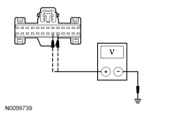
| A2 CHECK THE IPC VOLTAGE SUPPLY WITH KEY OFF | |
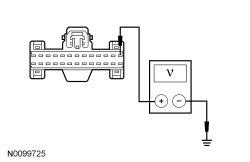 | Yes
GO to A3 . No VERIFY the SJB fuse 26 (10A) is OK. If OK, REPAIR the circuit in question. If not OK, REFER to the Wiring Diagrams manual to identify the possible causes of the circuit short. TEST the system for normal operation. |
| A3 CHECK THE GROUND CIRCUIT FOR AN OPEN | |
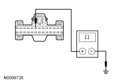 | Yes
GO to A4 . No REPAIR the circuit. TEST the system for normal operation. |
| A4 CHECK FOR CORRECT IPC OPERATION | |
| Yes
INSTALL a new IPC . REFER to Instrument Panel Cluster (IPC) in this section. TEST the system for normal operation. No The system is operating correctly at this time. The concern may have been caused by a loose or corroded connector. |
Pinpoint Test B: Incorrect Fuel Gauge Indication
Diagnostics in this manual assume a certain skill level and knowledge of Ford-specific diagnostic practices. Refer to Diagnostic Methods in Diagnostic Methods in Section 100-00 for information regarding these diagnostic practices.
Refer to Wiring Diagrams Cell 60 , Instrument Cluster for schematic and connector information.
The fuel tank is a saddle tank design with 2 variable resistance senders, driven by floats, that provide resistances related to fuel level in each side of the fuel tank to the Instrument Panel Cluster (IPC). The fuel level is determined using variable resistance fuel sender units, with an approximate resistance range between 180 ohms ± 4 ohms at empty (E) and 10 ohms ± 2 ohms at full (F). The IPC provides a reference voltage to the fuel pump module (LH side) and the fuel level sensor (RH side) through individual signal circuits and receives a return through the signal return circuits from both the fuel pump module and fuel level sensor. As the fuel level changes, a float actuates a variable resistor on the fuel pump module and the fuel level sensor, raising or lowering the fuel level signal voltage depending on the resistance of the fuel level sender (float and card) or fuel level sensor. The IPC monitors the changes in voltage from both senders and commands the fuel gauge with a corresponding movement of the pointer. If the IPC detects the fuel level sensor circuitry is open, the fuel gauge defaults to the fuel pump module value only and the fuel gauge defaults to the empty (E) position. If the IPC detects the fuel pump module circuitry is open, the fuel gauge defaults to the empty (E) position.
The IPC uses 4 different operating modes to calculate the fuel level:
After a fuel fill up, the time for the fuel gauge to move from empty (E) to full (F) ranges from 2 seconds to 55 minutes depending on which operating mode the fuel gauge is in.
The default fuel gauge mode is called the anti-slosh mode. To prevent fuel gauge changes from fuel slosh (gauge instability due to changes in fuel sensor readings caused by fuel moving around in the tank), the fuel gauge takes approximately 55 minutes to go from empty (E) to full (F).
The ignition OFF fueling mode (2 seconds to read empty [E] to full [F]) requires 3 conditions be met:
If these conditions are not met, the fuel gauge stays in the anti-slosh mode, which results in a slow to read full (F) event.
The ignition ON fueling mode (approximately 90 seconds to read empty [E] to full [F]) requires the following conditions be met:
In ignition ON fueling mode, a 30-second timer activates after the transmission is put into the PARK (P) position. When the 30-second time has elapsed and at least 15% of the vehicle's fuel capacity has been added, the fuel gauge response time is 60 seconds to read from empty (E) to full (F). When the transmission is shifted out of PARK (P), the fuel gauge strategy reverts to the anti-slosh mode. The ignition ON fueling mode prevents slow to read full events from happening if the customer refuels the vehicle with the ignition in the RUN mode.
Recovery mode is incorporated into the IPC strategy to recover from a missing fuel level input after a refueling event. Missing fuel level inputs result from intermittent opens in the fuel sensor or its circuits. Recovery mode (empty [E] to full [F] approximately 20 minutes) is initiated when the following 2 conditions are met:
Instrument Panel Cluster (IPC) DTCs
| DTC Description | Fault Trigger Conditions |
|---|---|
| A continuous and on-demand DTC that sets in the IPC if the IPC detects that the fuel pump module (LH side) is out of range on the input circuit with a short to ground for 33 seconds. The IPC defaults the fuel gauge to empty (E) once the IPC detects a fault and sets DTC B1A75:11. |
| A continuous and on-demand DTC that sets in the IPC if the IPC detects that the fuel pump module (LH side) is out of range on the input circuit with an open or short to voltage on circuit VMC11 (YE/VT) or circuit RMC32 (GN/BU) for 33 seconds. The IPC defaults the fuel gauge to empty (E) once the IPC detects a fault and sets DTC B1A75:15. |
| A continuous and on-demand DTC that sets in the IPC if the IPC detects that the fuel level sensor (RH side) is out of range on the input circuit with a short to ground for 33 seconds. The IPC defaults the fuel gauge to empty (E) once the IPC detects a fault and sets DTC B1A76:11. |
| A continuous and on-demand DTC that sets in the IPC if the IPC detects that the fuel level sensor (RH side) is out of range on the input circuit with an open or short to voltage on circuit RMC33 (WH/VT) for 33 seconds. The IPC defaults the fuel gauge to empty (E) once the IPC detects a fault and sets DTC B1A76:15. |
| NOTE: Normal operation of the fuel delivery system allows the fuel sensor side of the fuel tank (RH side) to have less fuel than the side with the fuel pump module (LH side). A continuous DTC that sets when the IPC detects a large discrepancy in the amount of fuel (based on input from both fuel sensors) between both sides of the fuel tank. |
PCM DTCs
| DTC Description | Fault Trigger Conditions |
|---|---|
| Sets when the PCM determines the value of the fuel level input signal is stuck, that the fuel level input signal does not change or does not correspond with the calculated fuel usage. |
| Sets when the PCM determines the fuel level input signal repeatedly moves in and out of range, exceeding the minimum or maximum allowable calibrated parameters for a specified fuel fill percentage in the fuel tank. |
| Sets in the PCM when the PCM detects a short to ground on the fuel pump module signal circuit based on the messaged input received from the IPC . |
| Sets in the PCM when the PCM detects an open or a short to voltage on the fuel pump module signal circuit based on the messaged input received from the IPC . |
| Sets when the PCM determines the value of the fuel level sensor input signal is stuck, that the fuel level input signal does not change or does not correspond with the calculated fuel usage. |
| Sets when the PCM determines the fuel level sensor input signal repeatedly moves in and out of range, exceeding the minimum or maximum allowable calibrated parameters for a specified fuel fill percentage in the fuel tank. |
| Sets in the PCM when the PCM detects a short to ground on the fuel level sensor signal circuit based on the messaged input received from the IPC . |
| Sets in the PCM when the PCM detects an open or short to voltage on the fuel level sensor signal circuit on the messaged input received from the IPC . |
This pinpoint test is intended to diagnose the following:
NOTICE: Use the correct probe adapter(s) when making measurements. Failure to use the correct probe adapter(s) may damage the connector.
| Test Step | Result / Action to Take |
|---|---|
| B1 RETRIEVE THE RECORDED DTCs FROM THE IPC SELF-TEST | |
| Yes
For DTC B1A75:11 or DTC B1A76:11, GO to B3 . For DTC B1A75:15, GO to B7 . For DTC B1A76:15, GO to B12 . For DTC P1243:06, GO to B16 . No GO to B2 . |
| B2 CARRY OUT THE IPC FUEL GAUGE ACTIVE COMMAND USING THE SCAN TOOL | |
| Yes
GO to B16 . No INSTALL a new IPC . REFER to Instrument Panel Cluster (IPC) in this section. TEST the system for normal operation. |
| B3 CHECK THE FUEL SENDER FOR A SHORT TO GROUND | |
| Yes
INSTALL a new fuel pump module (DTC B1A75:11) or fuel level sensor (DTC B1A76:11). REFER to Section 310-01 . CLEAR the DTCs. REPEAT the self-test. No GO to B4 . |
| B4 CHECK THE FUEL LEVEL SIGNAL CIRCUITS FOR A SHORT TO GROUND | |
 | Yes
For DTC B1A75:11, GO to B5 . For DTC B1A76:11, GO to B6 . No REPAIR the circuit in question. CLEAR the DTCs. REPEAT the self-test. |
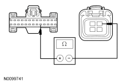
| B5 CHECK THE FUEL PUMP MODULE SIGNAL AND RETURN CIRCUITS FOR A SHORT TOGETHER | |
 | Yes
GO to B20 . No REPAIR the circuit in question. CLEAR the DTCs. REPEAT the self-test. |
| B6 CHECK THE FUEL LEVEL SENSOR SIGNAL AND RETURN CIRCUITS FOR A SHORT TOGETHER | |
 | Yes
GO to B20 . No REPAIR the circuit in question. CLEAR the DTCs. REPEAT the self-test. |
| B7 CHECK THE FUEL PUMP MODULE CIRCUITRY FOR A SHORT TO VOLTAGE | |
 | Yes
GO to B8 . No GO to B9 . |
| B8 CHECK THE FUEL PUMP MODULE FOR A SHORT TO VOLTAGE | |
| Yes
REPAIR the circuit in question. CLEAR the DTCs. REPEAT the self-test. No INSTALL a new fuel pump module. REFER to Section 310-01 . CLEAR the DTCs. REPEAT the self-test. |
| B9 CHECK THE FUEL PUMP MODULE CIRCUITRY FOR AN OPEN | |
  | Yes
REMOVE the jumper wire. GO to B10 . No REMOVE the jumper wire. GO to B11 . |
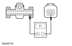
| B10 CHECK THE FUEL PUMP MODULE FOR AN OPEN | |
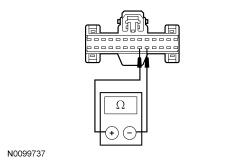
NOTE: The fuel level sensor resistance varies from 180 ± 4 ohms when empty (E) to 10 ± 2 ohms when full (F). 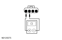 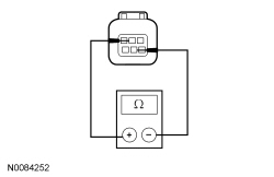 | Yes
GO to B20 . No GO to B19 . |
| B11 CHECK THE FUEL LEVEL SIGNAL CIRCUIT FOR AN OPEN | |
  | Yes
REPAIR circuit RMC32 (GN/BU) for an open. CLEAR the DTCs. REPEAT the self-test. No REPAIR circuit VMC11 (YE/VT). CLEAR the DTCs. REPEAT the self-test. |
| B12 CHECK THE FUEL LEVEL SENSOR CIRCUITRY FOR A SHORT TO VOLTAGE | |
 | Yes
REPAIR the circuit in question. CLEAR the DTCs. REPEAT the self-test. No GO to B13 . |
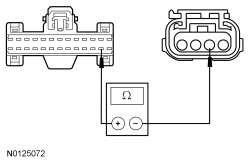
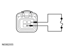
| B13 CHECK THE FUEL LEVEL SENSOR FOR AN OPEN | |
NOTE: The fuel level sensor resistance varies from 180 ± 4 ohms when empty (E) to 10 ± 2 ohms when full (F). 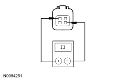 | Yes
GO to B14 . No INSTALL a new fuel level sensor. REFER to Section 310-01 . CLEAR the DTCs. REPEAT the self-test. |
| B14 CHECK THE FUEL LEVEL SENSOR CIRCUITRY FOR AN OPEN | |
 | Yes
REMOVE the jumper wire. GO to B20 . No REMOVE the jumper wire. GO to B15 . |
| B15 CHECK THE FUEL LEVEL SENSOR SIGNAL FOR AN OPEN | |
  | Yes
REPAIR circuit RMC33 (WH/VT) for an open. CLEAR the DTCs. REPEAT the self-test. No REPAIR circuit VMC23 (GN/OG). CLEAR the DTCs. REPEAT the self-test. |
| B16 INSPECT THE FUEL TANK | |
| Yes
GO to B17 . No INSTALL a new fuel tank. REFER to Section 310-01 . CLEAR the DTCs. REPEAT the self test. |
| B17 INSPECT THE FUEL TANK TRANSFER TUBE CONNECTIONS | |
| Yes
GO to B18 . No INSTALL a new fuel tank transfer tube, fuel pump module or fuel level sensor as necessary. REFER to Section 310-01 . CLEAR the DTCs. REPEAT the self test. |
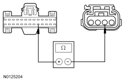
| B18 CHECK THE FUEL PUMP MODULE AND FUEL LEVEL SENSOR RESISTANCE READINGS | |
NOTE: The fuel pump module and fuel level sensor resistance varies from 180 ± 4 ohms when empty (E) to 10 ± 2 ohms when full (F). | Yes
INSTALL a new fuel tank. REFER to Section 310-01 . CLEAR the DTCs. REPEAT the self-test. No For the fuel pump module, GO to B19 . For the fuel level sensor, INSTALL a new fuel level sensor. REFER to Section 310-01 . CLEAR the DTCs. REPEAT the self-test. |
| B19 CHECK THE FUEL LEVEL SENDER (FLOAT AND CARD) | |
NOTE: The fuel level sender (float and card) resistance measures between 180 ± 4 ohms at the lower stop position and 10 ± 2 ohms at the upper stop position. 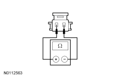 | Yes
INSTALL a new fuel pump module. REFER to Section 310-01 . CLEAR the DTCs. REPEAT the self-test. No INSTALL a new fuel level sender (float and card). REFER to Section 310-01 . CLEAR the DTCs. REPEAT the self-test. |
| B20 CHECK FOR CORRECT IPC OPERATION | |
| Yes
INSTALL a new IPC . REFER to Instrument Panel Cluster (IPC) in this section. TEST the system for normal operation. No The system is operating correctly at this time. The concern may have been caused by a loose or corroded connector. CLEAR the DTCs. REPEAT the self-test. |
Pinpoint Test C: The Engine Temperature Gauge Is Inoperative
Diagnostics in this manual assume a certain skill level and knowledge of Ford-specific diagnostic practices. Refer to Diagnostic Methods in Diagnostic Methods in Section 100-00 for information regarding these diagnostic practices.
The PCM uses the Cylinder Head Temperature (CHT) sensor to measure the engine temperature. The Instrument Panel Cluster (IPC) receives the engine temperature data from the PCM over the High Speed Controller Area Network (HS-CAN) communication bus. The IPC monitors the engine temperature data received from the PCM and commands the engine temperature gauge indication with a corresponding movement of the pointer.
If the engine temperature data is missing for 5 seconds or less or if the IPC receives invalid engine temperature data for 5 seconds or less, the IPC defaults the engine temperature gauge to the last setting, based upon the last known good temperature status message. If the IPC does not receive the engine temperature status message from the PCM for more than 5 seconds, the IPC sets DTC U0100:87 in continuous memory and defaults the temperature gauge to cold (C). If the engine temperature data is deemed invalid by the IPC for 5 seconds or more, the IPC sets DTC U0401:68 and defaults the engine temperature gauge to cold (C).
NOTE: If DTC U0100:87 is set in the IPC , other observable symptoms can be an inoperative tachometer, speedometer or odometer.
This pinpoint test is intended to diagnose the following:
| Test Step | Result / Action to Take |
|---|---|
| C1 RETRIEVE THE RECORDED PCM DTCs FROM THE KOEO SELF-TEST | |
| Yes
REFER to the Powertrain Control/Emissions Diagnosis (PC/ED) manual. No GO to C2 . |
| C2 RETRIEVE THE RECORDED DTCs FROM THE IPC SELF-TEST | |
| Yes
For DTC U0100:87, GO to Pinpoint Test AS . For all other DTCs, REFER to DTC Charts in this section. No GO to C3 . |
| C3 CARRY OUT THE IPC ENGINE TEMPERATURE GAUGE ACTIVE COMMAND USING THE SCAN TOOL | |
| Yes
INSTALL a new PCM. REFER to Section 303-14 . TEST the system for normal operation. No INSTALL a new IPC . REFER to Instrument Panel Cluster (IPC) in this section. TEST the system for normal operation. |
Pinpoint Test D: Incorrect Engine Temperature Gauge Indication
Diagnostics in this manual assume a certain skill level and knowledge of Ford-specific diagnostic practices. Refer to Diagnostic Methods in Diagnostic Methods in Section 100-00 for information regarding these diagnostic practices.
The PCM uses the Cylinder Head Temperature (CHT) sensor to measure the engine temperature. The Instrument Panel Cluster (IPC) receives the engine temperature data from the PCM over the High Speed Controller Area Network (HS-CAN) communication bus. The IPC monitors the engine temperature data received from the PCM and commands the engine temperature gauge indication with a corresponding movement of the pointer.
The PCM provides 2 modes or levels of fail-safe cooling for gasoline engines, which provides a visual indication to the driver that the engine is overheating while reducing the engine power to lower the engine temperature. When the PCM sends the IPC a fail-safe mode 1 or 2 command, the IPC drives the temperature gauge to the full hot (H) position.
If the engine temperature data is missing for 5 seconds or less or if the IPC receives invalid engine temperature data for 5 seconds or less, the IPC defaults the engine temperature gauge to the last setting, based upon the last known good temperature status message. If the IPC does not receive the engine temperature status message from the PCM for more than 5 seconds, the IPC sets DTC U0100:87 in continuous memory and defaults the engine temperature gauge to cold (C). If the engine temperature data is deemed invalid by the IPC for 5 seconds or more, the IPC sets DTC U0401:68 and defaults the engine temperature gauge to cold (C).
NOTE: If DTC U0100:87 is set in the IPC , other observable symptoms can be an inoperative tachometer, speedometer or odometer.
This pinpoint test is intended to diagnose the following:
| Test Step | Result / Action to Take | ||||||||
|---|---|---|---|---|---|---|---|---|---|
| D1 CHECK FOR CORRECT OPERATION OF THE COOLING SYSTEM | |||||||||
| Yes
GO to D2 . No REFER to Section 303-03A . | ||||||||
| D2 RETRIEVE THE RECORDED PCM DTCs FROM THE KOEO SELF-TEST | |||||||||
| Yes
DIAGNOSE all PCM DTCs first. REFER to the Powertrain Control/Emissions Diagnosis (PC/ED) manual. No GO to D3 . | ||||||||
| D3 RETRIEVE THE RECORDED DTCs FROM THE IPC SELF-TEST | |||||||||
| Yes
For DTC U0100:87, GO to Pinpoint Test AS . For DTC U0401:68, RETRIEVE and REPAIR all non-network DTCs in the PCM and other modules on the network. REFER to the Powertrain Control/Emissions Diagnosis (PC/ED) manual and REFER to Section 419-10 . For all other DTCs, REFER to DTC Charts in this section. No GO to D4 . | ||||||||
| D4 CARRY OUT THE ENGINE TEMPERATURE GAUGE ACTIVE COMMAND USING THE SCAN TOOL | |||||||||
| Yes
GO to D5 . No INSTALL a new IPC . REFER to Instrument Panel Cluster (IPC) in this section. TEST the system for normal operation. | ||||||||
| D5 CHECK THE ENGINE TEMPERATURE INPUT USING THE DEALER TEST MODE | |||||||||
| Yes
The engine temperature gauge is operating correctly at this time. No INSTALL a new IPC . REFER to Instrument Panel Cluster (IPC) in this section. TEST the system for normal operation. |
Pinpoint Test E: The Tachometer Is Inoperative
Diagnostics in this manual assume a certain skill level and knowledge of Ford-specific diagnostic practices. Refer to Diagnostic Methods in Diagnostic Methods in Section 100-00 for information regarding these diagnostic practices.
The PCM uses the Crankshaft Position (CKP) sensor to measure the engine rpm. The PCM sends the Instrument Panel Cluster (IPC) data over the High Speed Controller Area Network (HS-CAN) communication bus to command the tachometer gauge according to the data.
If the engine rpm data is invalid for 5 seconds or less or if the IPC does not receive the engine rpm data for 5 seconds or less, the IPC defaults the tachometer to the last setting, based upon the last known good rpm message. If the IPC does not receive the engine rpm data from the PCM for more than 5 seconds, the IPC sets DTC U0100:87 in continuous memory and defaults the tachometer to 0 rpm. If the engine rpm data is deemed invalid by the IPC for 5 seconds or longer, the IPC sets DTC U0401:68 and defaults the tachometer to 0 rpm.
NOTE: If DTC U0100:87 is set in the IPC , other observable symptoms can be an inoperative speedometer, temperature gauge or odometer.
This pinpoint test is intended to diagnose the following:
| Test Step | Result / Action to Take |
|---|---|
| E1 RETRIEVE THE RECORDED PCM DTCs FROM THE KOEO SELF-TEST | |
| Yes
DIAGNOSE all PCM DTCs first. REFER to the Powertrain Control/Emissions Diagnosis (PC/ED) manual. No GO to E2 . |
| E2 CARRY OUT THE TACHOMETER ACTIVE COMMAND USING THE SCAN TOOL | |
| Yes
GO to E3 . No INSTALL a new IPC . REFER to Instrument Panel Cluster (IPC) in this section. TEST the system for normal operation. |
| E3 RETRIEVE THE RECORDED DTCs FROM THE IPC SELF-TEST | |
| Yes
For DTC U0100:87, GO to Pinpoint Test AS . For DTC U0401:68, RETRIEVE and REPAIR all non-network DTCs in the PCM and other modules on the network. REFER to the Powertrain Control/Emissions Diagnosis (PC/ED) manual and REFER to Section 419-10 . For all other DTCs, REFER to DTC Charts in this section. No INSTALL a new PCM. REFER to Section 303-14 . TEST the system for normal operation. |
Pinpoint Test F: Incorrect Tachometer Indication
Diagnostics in this manual assume a certain skill level and knowledge of Ford-specific diagnostic practices. Refer to Diagnostic Methods in Section 100-00 for information regarding these diagnostic practices.
The PCM uses the Crankshaft Position (CKP) sensor to measure the engine rpm. The PCM sends the Instrument Panel Cluster (IPC) data over the High Speed Controller Area Network (HS-CAN) communication bus to command the tachometer according to the data.
If the engine rpm data is invalid for 5 seconds or less or if the IPC does not receive the engine rpm data for 5 seconds or less, the IPC defaults the tachometer to the last setting, based upon the last known good rpm message. If the IPC does not receive the engine rpm data from the PCM for more than 5 seconds, the IPC sets DTC U0100:87 in continuous memory and defaults the tachometer to 0 rpm. If the engine rpm data is deemed invalid by the IPC for 5 seconds or longer, the IPC sets DTC U0401:68 and defaults the tachometer to 0 rpm.
NOTE: If DTC U0100:87 is set in the IPC , other observable symptoms can be an inoperative speedometer, temperature gauge or odometer.
This pinpoint test is intended to diagnose the following:
| Test Step | Result / Action to Take |
|---|---|
| F1 RETRIEVE THE RECORDED PCM DTCs FROM THE KOEO SELF-TEST | |
| Yes
DIAGNOSE all PCM DTCs first. REFER to the Powertrain Control/Emissions Diagnosis (PC/ED) manual. No GO to F2 . |
| F2 RETRIEVE THE RECORDED DTCs FROM THE IPC SELF-TEST | |
| Yes
For DTC U0100:87, GO to Pinpoint Test AS . For DTC U0401:68, RETRIEVE and REPAIR all non-network DTCs in the PCM and other modules on the network. REFER to the Powertrain Control/Emissions Diagnosis (PC/ED) manual and REFER to Section 419-10 . For all other DTCs, REFER to DTC Charts in this section. No GO to F3 . |
| F3 CARRY OUT THE TACHOMETER ACTIVE COMMAND USING THE SCAN TOOL | |
| Yes
GO to F4 . No INSTALL a new IPC . REFER to Instrument Panel Cluster (IPC) in this section. TEST the system for normal operation. |
| F4 CHECK THE ENGINE RPM INPUT USING THE IPC DEALER TEST MODE | |
| Yes
The tachometer is operating correctly at this time. No INSTALL a new IPC . REFER to Instrument Panel Cluster (IPC) in this section. TEST the system for normal operation. |
Pinpoint Test G: The Speedometer Is Inoperative
Diagnostics in this manual assume a certain skill level and knowledge of Ford-specific diagnostic practices. Refer to Diagnostic Methods in Section 100-00 for information regarding these diagnostic practices.
The Instrument Panel Cluster (IPC) receives the vehicle speed signal from the PCM over the High Speed Controller Area Network (HS-CAN) communication bus. The PCM receives vehicle speed from the Output Shaft Speed (OSS) sensor and uses axle ratio and tire Vehicle Identification (VID) block to generate the vehicle speed data sent to the IPC . The IPC monitors the vehicle speed input from the PCM and commands the speedometer with a corresponding movement of the pointer.
If the vehicle speed data is missing for 5 seconds or less or if the IPC receives invalid vehicle speed data for 5 seconds or less, the IPC defaults the speedometer to the last setting, based upon the last known good vehicle speed message. If the IPC does not receive the vehicle speed data from the PCM for more than 5 seconds, the IPC sets DTC U0100:87 in continuous memory and defaults the speedometer to 0 km/h (0 mph). If the vehicle speed data received is deemed invalid by the IPC for 5 seconds or longer, the IPC sets DTC U0401:68 and defaults the speedometer to 0 km/h (0 mph).
NOTE: If DTC U0100:87 is set in the IPC , other observable symptoms can be an inoperative tachometer, temperature gauge or odometer.
This pinpoint test is intended to diagnose the following:
| Test Step | Result / Action to Take |
|---|---|
| G1 CARRY OUT THE IPC SPEEDOMETER ACTIVE COMMAND USING THE SCAN TOOL | |
| Yes
GO to G2 . No INSTALL a new IPC . REFER to Instrument Panel Cluster (IPC) in this section. TEST the system for normal operation. |
| G2 RETRIEVE THE RECORDED PCM DTCs FROM THE KOEO SELF-TEST | |
| Yes
DIAGNOSE all PCM DTCs first. REFER to the Powertrain Control/Emissions Diagnosis (PC/ED) manual. No GO to G3 . |
| G3 RETRIEVE THE RECORDED DTCs FROM THE IPC SELF-TEST | |
| Yes
For DTC U0100:87, GO to Pinpoint Test AS . For DTC U0401:68, RETRIEVE and REPAIR all non-network DTCs in the PCM and other modules on the network. REFER to the Powertrain Control/Emissions Diagnosis (PC/ED) manual and REFER to Section 419-10 . For all other DTCs, REFER to DTC Charts in this section. No INSTALL a new PCM. REFER to Section 303-14 . TEST the system for normal operation. |
Pinpoint Test H: Incorrect Speedometer Indication
Diagnostics in this manual assume a certain skill level and knowledge of Ford-specific diagnostic practices. Refer to Diagnostic Methods in Section 100-00 for information regarding these diagnostic practices.
The Instrument Panel Cluster (IPC) receives the vehicle speed signal from the PCM over the High Speed Controller Area Network (HS-CAN) communication bus. The PCM receives vehicle speed from the Output Shaft Speed (OSS) sensor and uses axle ratio and tire Vehicle Identification (VID) block to generate the vehicle speed data sent to the IPC . The IPC monitors the vehicle speed input from the PCM and commands the speedometer with a corresponding movement of the pointer.
A configurable item such as tire size could affect the accuracy of the speedometer.
If the vehicle speed data is missing for 5 seconds or less or if the IPC receives invalid vehicle speed data for 5 seconds or less, the IPC defaults the speedometer to the last setting, based upon the last known good vehicle speed message. If the IPC does not receive the vehicle speed data from the PCM for more than 5 seconds, the IPC sets DTC U0100:87 in continuous memory and defaults the speedometer to 0 km/h (0 mph). If the vehicle speed data received is deemed invalid by the IPC for 5 seconds or longer, the IPC sets DTC U0401:68 and defaults the speedometer to 0 km/h (0 mph).
NOTE: If DTC U0100:87 is set in the IPC , other observable symptoms can be an inoperative tachometer, temperature gauge or odometer.
This pinpoint test is intended to diagnose the following:
| Test Step | Result / Action to Take |
|---|---|
| H1 OBSERVE THE SPEEDOMETER OPERATION | |
| Yes
GO to H2 . No INSTALL a new IPC . REFER to Instrument Panel Cluster (IPC) in this section. TEST the system for normal operation. |
| H2 CHECK THE TIRE SIZE CONFIGURATION | |
| Yes
GO to H3 . No CONFIGURE the PCM for the correct tire size. TEST the system for normal operation. |
| H3 RETRIEVE THE RECORDED PCM DTCs FROM THE KOEO SELF-TEST | |
| Yes
DIAGNOSE all PCM DTCs first. REFER to the Powertrain Control/Emissions Diagnosis (PC/ED) manual. No GO to H4 . |
| H4 RETRIEVE THE RECORDED DTCs FROM THE IPC SELF-TEST | |
| Yes
For DTC U0100:87, GO to Pinpoint Test AS . For DTC U0401:68, RETRIEVE and REPAIR all non-network DTCs in the PCM and other modules on the network. REFER to the Powertrain Control/Emissions Diagnosis (PC/ED) manual and REFER to Section 419-10 . For all other DTCs, REFER to DTC Charts in this section. No GO to H5 . |
| H5 CARRY OUT THE IPC SPEEDOMETER ACTIVE COMMAND USING THE SCAN TOOL | |
| Yes
GO to H6 . No INSTALL a new IPC . REFER to Instrument Panel Cluster (IPC) in this section. TEST the system for normal operation. |
| H6 CHECK THE PCM VSS PIDs | |
| Yes
The speedometer is operating correctly at this time. No INSTALL a new IPC . REFER to Instrument Panel Cluster (IPC) in this section. TEST the system for normal operation. |
Pinpoint Test I: The Virtual Accelerometer/Track Applications Functions Are Inoperative (If Equipped)
Diagnostics in this manual assume a certain skill level and knowledge of Ford-specific diagnostic practices. Refer to Diagnostic Methods in Section 100-00 for information regarding these diagnostic practices.
The Instrument Panel Cluster (IPC) receives the accelerometer data from the ABS module and the brake pedal applied status from the PCM over the High Speed Controller Area Network (HS-CAN) communication bus.
If the accelerometer data is invalid or unknown for more than 5 seconds, the IPC sets DTC U0415:00 (invalid) or U0415:81 (unknown) in continuous memory and defaults the marker (red dot) in the accelerometer display off. If the accelerometer data is missing for more than 5 seconds, the IPC sets DTC U0121:00 in continuous memory and defaults the marker (red dot) in the accelerometer display off.
This pinpoint test is intended to diagnose the following:
| Test Step | Result / Action to Take |
|---|---|
| I1 CHECK THE SPEEDOMETER OPERATION | |
| Yes
GO to I2 . No GO to Pinpoint Test G . |
| I2 RETRIEVE THE RECORDED DTCs FROM THE IPC SELF-TEST | |
| Yes
For DTC U0121:00, GO to Pinpoint Test AT . For all other DTCs, REFER to DTC Charts in this section. No GO to I3 . |
| I3 RETRIEVE THE RECORDED DTCs FROM THE ABS MODULE SELF-TEST | |
| Yes
REFER to Section 206-09 . No GO to I4 . |
| I4 VERIFY THE VEHICLE IS CONFIGURED FOR TRACK APPLICATIONS | |
| Yes
INSTALL a new IPC . REFER to Instrument Panel Cluster (IPC) in this section. TEST the system for normal operation. No CARRY OUT the PMI using As-Built data for the IPC . TEST the system for normal operation. If the concern is still present, the vehicle was not equipped with track applications. |
Pinpoint Test J: A Virtual Gauge Is Inoperative (Except Accelerometer And Voltage Gauges) (If Equipped)
Diagnostics in this manual assume a certain skill level and knowledge of Ford-specific diagnostic practices. Refer to Diagnostic Methods in Section 100-00 for information regarding these diagnostic practices.
The Instrument Panel Cluster (IPC) receives data from the PCM over the High Speed Controller Area Network (HS-CAN) communication bus to control the air/fuel ratio, boost/vacuum (GT500), inlet air temperature, oil temperature and transmission oil temperature virtual gauges. The IPC monitors the data received from the PCM and commands the appropriate gauge indication.
If a virtual gauge data is missing for less than 5 seconds, the IPC defaults the gauge to the last setting, based upon the last known good message received. If the IPC does not receive the virtual gauge data from the PCM for 5 seconds or more, the IPC sets DTC U0100:87 in continuous memory and defaults the menu display to dashes (------) and the gauge to the lowest setting.
This pinpoint test is intended to diagnose the following:
| Test Step | Result / Action to Take |
|---|---|
| J1 RETRIEVE THE RECORDED PCM DTCs FROM THE KOEO SELF-TEST | |
| Yes
REFER to the Powertrain Control/Emissions Diagnosis (PC/ED) manual. No GO to J2 . |
| J2 RETRIEVE THE RECORDED DTCs FROM THE IPC SELF-TEST | |
| Yes
For DTC U0100:87, GO to Pinpoint Test AS . For all other DTCs, REFER to DTC Charts in this section. No GO to J3 . |
| J3 VERIFY THE VEHICLE IS CONFIGURED FOR VIRTUAL GAUGES | |
| Yes
GO to J4 . No CARRY OUT the PMI using As-Built data for the IPC . TEST the system for normal operation. If the concern is still present, the vehicle was not equipped with track applications. |
| J4 VERIFY GAUGE MODE IS SELECTED | |
| Yes
The virtual gauge is functioning correctly at this time. The gauge in question may not have been selected from the menu. No INSTALL a new IPC . REFER to Instrument Panel Cluster (IPC) in this section. TEST the system for normal operation. |
Pinpoint Test K: The Virtual Voltage Gauge Is Inoperative (If Equipped)
Diagnostics in this manual assume a certain skill level and knowledge of Ford-specific diagnostic practices. Refer to Diagnostic Methods in Section 100-00 for information regarding these diagnostic practices.
The Instrument Panel Cluster (IPC) uses the B+ hot at all times voltage from the Smart Junction Box (SJB) to measure and display the current operating voltage.
This pinpoint test is intended to diagnose the following:
| Test Step | Result / Action to Take |
|---|---|
| K1 VERIFY THE VEHICLE IS CONFIGURED FOR VIRTUAL GAUGES | |
| Yes
GO to K2 . No CARRY OUT the PMI using As-Built data for the IPC . TEST the system for normal operation. If the concern is still present, the vehicle was not equipped with track applications. |
| K2 VERIFY GAUGE MODE IS SELECTED | |
| Yes
GO to K3 . No INSTALL a new IPC . REFER to Instrument Panel Cluster (IPC) in this section. TEST the system for normal operation. |
| K3 CHECK THE IPC VOLTAGE SUPPLY WITH KEY OFF | |
| Yes
GO to K4 . No VERIFY the SJB fuse 26 (10A) is OK. If OK, REPAIR the circuit in question. If not OK, REFER to the Wiring Diagrams manual to identify the possible causes of the circuit short. TEST the system for normal operation. |
| K4 CHECK FOR CORRECT IPC OPERATION | |
| Yes
INSTALL a new IPC . REFER to Instrument Panel Cluster (IPC) in this section. TEST the system for normal operation. No The system is operating correctly at this time. The concern may have been caused by a loose or corroded connector. |
Pinpoint Test L: The Odometer Is Inoperative
Diagnostics in this manual assume a certain skill level and knowledge of Ford-specific diagnostic practices. Refer to Diagnostic Methods in Section 100-00 for information regarding these diagnostic practices.
The Instrument Panel Cluster (IPC) receives the odometer rolling count data from the PCM over the High Speed Controller Area Network (HS-CAN) communication bus. The IPC monitors the odometer rolling count input from the PCM and commands the odometer with a display in the message center display area.
If the IPC does not receive the odometer rolling count data or if the rolling count data is deemed invalid from the PCM for less than 5 seconds, the IPC displays the mileage based upon the last good known input.
If the IPC does not receive the odometer rolling count data or if the rolling count data is deemed invalid from the PCM for 5 seconds or longer, the IPC sets DTC U0100:87 in continuous memory and defaults the odometer display to all dashes (-----).
If the Non-Volatile Memory (NVM) is corrupted, the message center displays ERROR.
NOTE: If DTC U0100:87 is set in the IPC , other observable symptoms can be an inoperative speedometer, tachometer or temperature gauge.
This pinpoint test is intended to diagnose the following:
| Test Step | Result / Action to Take |
|---|---|
| L1 CHECK FOR CORRUPTED NVM | |
| Yes
INSTALL a new IPC . REFER to Instrument Panel Cluster (IPC) in this section. TEST the system for normal operation. No GO to L2 . |
| L2 RETRIEVE THE RECORDED PCM DTCs FROM THE KOEO SELF-TEST | |
| Yes
DIAGNOSE all PCM DTCs first. REFER to the Powertrain Control/Emissions Diagnosis (PC/ED) manual. No GO to L3 . |
| L3 RETRIEVE THE RECORDED DTCs FROM THE IPC SELF-TEST | |
| Yes
For DTC U0100:87, GO to Pinpoint Test AS . For DTC U0401:68, RETRIEVE and REPAIR all non-network DTCs in the PCM and other modules on the network. REFER to the Powertrain Control/Emissions Diagnosis (PC/ED) manual and REFER to Section 419-10 . For all other DTCs, REFER to DTC Charts in this section. No INSTALL a new IPC . REFER to Instrument Panel Cluster (IPC) in this section. TEST the system for normal operation. |
Pinpoint Test M: The Low Oil Pressure Warning Indicator Is Never/Always On
Diagnostics in this manual assume a certain skill level and knowledge of Ford-specific diagnostic practices. Refer to Diagnostic Methods in Section 100-00 for information regarding these diagnostic practices.
Refer to Wiring Diagrams Cell 60 , Instrument Cluster for schematic and connector information.
The Instrument Panel Cluster (IPC) provides a reference voltage to the engine oil pressure switch. When the oil pressure is within normal ranges, the engine oil pressure switch closes to ground, pulling the reference voltage low in the IPC . The IPC senses the low reference voltage and turns off the low oil pressure warning indicator. When the engine oil pressure is low, the engine oil pressure switch opens, sending the reference voltage high in the IPC . The IPC senses the high voltage and turns the low oil pressure warning indicator on.
This pinpoint test is intended to diagnose the following:
NOTICE: Use the correct probe adapter(s) when making measurements. Failure to use the correct probe adapter(s) may damage the connector.
NOTE: Failure to disconnect the battery when instructed results in false resistance readings. Refer to Section 414-01 .
| Test Step | Result / Action to Take |
|---|---|
| M1 CARRY OUT THE IPC INDICATOR LAMP CONTROL ACTIVE COMMAND USING THE SCAN TOOL | |
| Yes
If the low oil pressure warning indicator is always on, GO to M4 . If the low oil pressure warning indicator is never on, GO to M2 . No INSTALL a new IPC . REFER to Instrument Panel Cluster (IPC) in this section. TEST the system for normal operation. |
| M2 CHECK FOR A STUCK CLOSED ENGINE OIL PRESSURE SWITCH | |
| Yes
INSTALL a new engine oil pressure switch. Refer to the appropriate section in Group 303 for the procedure. TEST the system for normal operation. No GO to M3 . |
| M3 CHECK THE OIL PRESSURE INPUT CIRCUIT FOR A SHORT TO GROUND | |
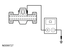 | Yes
GO to M7 . No REPAIR the circuit. TEST the system for normal operation. |
| M4 CHECK FOR A STUCK OPEN ENGINE OIL PRESSURE SWITCH | |
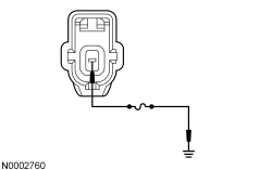 | Yes
REMOVE the jumper wire. GO to M6 . No LEAVE the jumper wire connected. GO to M5 . |
| M5 CHECK THE OIL PRESSURE INPUT CIRCUIT FOR AN OPEN | |
| Yes
REMOVE the jumper wire. GO to M7 . No REMOVE the jumper wire. REPAIR the circuit. TEST the system for normal operation. |
| M6 CHECK THE OIL PRESSURE | |
| Yes
INSTALL a new engine oil pressure switch. Refer to the appropriate section in Group 303 for the procedure. TEST the system for normal operation. No REFER to Section 303-00 to continue diagnosis of the low engine oil pressure concern. |
| M7 CHECK FOR CORRECT IPC OPERATION | |
| Yes
INSTALL a new IPC . REFER to Instrument Panel Cluster (IPC) in this section. TEST the system for normal operation. No The system is operating correctly at this time. The concern may have been caused by a loose or corroded connector. |
Pinpoint Test N: The Engine Over-Temperature Warning Indicator Is Never/Always On (Base IPC )
Diagnostics in this manual assume a certain skill level and knowledge of Ford-specific diagnostic practices. Refer to Diagnostic Methods in Section 100-00 for information regarding these diagnostic practices.
The Instrument Panel Cluster (IPC) receives the engine over-temperature command from the PCM over the High Speed Controller Area Network (HS-CAN) communication bus. If the PCM detects an engine over-temperature condition or has entered into the fail-safe cooling mode, the PCM sends a command to the IPC to turn the engine over-temperature warning indicator on. The PCM incorporates 2 strategies for fail-safe cooling in the event that the engine has reached an over-temperature condition. The first strategy is when the PCM provides engine operation but takes on the limp home strategy. The second strategy is when the PCM determines that the engine is sufficiently over-temperature and is about to be shut down by the PCM.
If the engine over-temperature status message is missing or invalid for less than 5 seconds, the engine over-temperature warning indicator remains in the last on/off state, based upon the last known good engine over-temperature status message received. If the engine over-temperature message is invalid for more than 5 seconds, the IPC sets DTC U0401:68 in continuous memory and defaults the engine message center indicator on.
If the engine over-temperature status message is missing for more than 5 seconds, the IPC sets DTC U0100:87 in continuous memory and defaults the engine over-temperature warning indicator on.
NOTE: If DTC U0100:87 is set in the IPC , other observable symptoms can be an inoperative speedometer, tachometer or odometer.
This pinpoint test is intended to diagnose the following:
| Test Step | Result / Action to Take |
|---|---|
| N1 CARRY OUT THE IPC WARNING LAMPS AND CHIME ACTIVE COMMAND USING THE SCAN TOOL | |
| Yes
GO to N2 . No INSTALL a new IPC . REFER to Instrument Panel Cluster (IPC) in this section. TEST the system for normal operation. |
| N2 RETRIEVE THE RECORDED DTCs FROM THE PCM KOEO SELF-TEST | |
| Yes
REFER to the Powertrain Control/Emissions Diagnosis (PC/ED) manual. No GO to N3 . |
| N3 RETRIEVE THE RECORDED DTCs FROM THE IPC SELF-TEST | |
| Yes
For DTC U0100:87, GO to Pinpoint Test AS . For DTC U0401:68, RETRIEVE and REPAIR all non-network DTCs in the PCM and other modules on the network. REFER to the Powertrain Control/Emissions Diagnosis (PC/ED) manual and REFER to Section 419-10 . For all other DTCs, REFER to DTC Charts in this section. No INSTALL a new PCM. REFER to Section 303-14 . TEST the system for normal operation. |
Pinpoint Test O: The Brake Warning Indicator is Never On
Diagnostics in this manual assume a certain skill level and knowledge of Ford-specific diagnostic practices. Refer to Diagnostic Methods in Section 100-00 for information regarding these diagnostic practices.
Refer to Wiring Diagrams Cell 60 , Instrument Cluster for schematic and connector information.
The Instrument Panel Cluster (IPC) uses 3 basic messaged inputs to control the brake warning indicator. The first 2 are the parking brake warning indicator switch and brake fluid level switch. The third is for the Electronic Brake Distribution (EBD), controlled by the ABS module. The parking brake warning indicator switch and the brake fluid level switch status are sent from the Smart Junction Box (SJB) over the Medium Speed Controller Area Network (MS-CAN) communication bus. The EBD message is sent from the ABS module over the High Speed Controller Area Network (HS-CAN) communication bus lines. The parking brake warning indicator switch and brake fluid level switch are both hardwired to the SJB . The parking brake warning indicator switch and the brake fluid level use an external ground circuit.
The SJB provides a reference voltage to both the parking brake warning indicator switch and the brake fluid level switch. When the parking brake is applied, the parking brake warning indicator switch closes to ground, pulling the parking brake input circuit low. When a low brake fluid level condition exists, the low brake fluid level switch closes to ground, pulling the brake fluid level input circuit low. The SJB monitors the parking brake and the brake fluid level inputs sending the SJB a message to turn the brake warning indicator on or when the parking brake is applied. When the ABS module detects a base brake system concern or other ABS-related concerns that affect the EBD function, the ABS module sends a message to the IPC to illuminate both the ABS warning indicator and the brake warning indicator.
This pinpoint test is intended to diagnose the following:
NOTICE: Use the correct probe adapter(s) when making measurements. Failure to use the correct probe adapter(s) may damage the connector.
NOTE: Failure to disconnect the battery when instructed results in false resistance readings. Refer to Section 414-01 .
| Test Step | Result / Action to Take |
|---|---|
| O1 DETERMINE IF THE BRAKE WARNING INDICATOR OPERATES WITH THE PARKING BRAKE | |
| Yes
GO to O7 . No GO to O2 . |
| O2 CARRY OUT THE IPC INDICATOR LAMP CONTROL ACTIVE COMMAND USING THE SCAN TOOL | |
| Yes
GO to O3 . No INSTALL a new IPC . REFER to Instrument Panel Cluster (IPC) in this section. TEST the system for normal operation. |
| O3 CHECK THE PARKING BRAKE WARNING INDICATOR SWITCH PID | |
| Yes
GO to O11 . No GO to O4 . |
| O4 CHECK THE PARKING BRAKE WARNING INDICATOR SWITCH | |
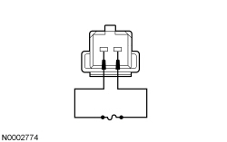 | Yes
REMOVE the jumper wire. INSTALL a new parking brake warning indicator switch. TEST the system for normal operation. No REMOVE the jumper wire. GO to O5 . |
| O5 CHECK THE PARKING BRAKE GROUND CIRCUIT FOR AN OPEN | |
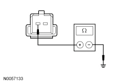 | Yes
GO to O6 . No REPAIR the circuit. TEST the system for normal operation. |
| O6 CHECK THE PARKING BRAKE SIGNAL CIRCUIT FOR AN OPEN | |
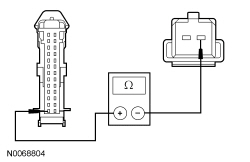 | Yes
GO to O11 . No REPAIR the circuit. TEST the system for normal operation. |
| O7 CHECK THE BRAKE FLUID LEVEL SWITCH OPERATION | |
| Yes
GO to O9 . No GO to O8 . |
| O8 CHECK THE BRAKE FLUID LEVEL INPUT CIRCUIT FOR A SHORT TOGETHER | |
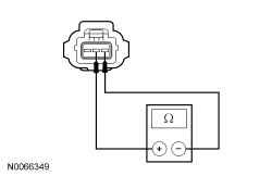 | Yes
GO to O11 . No REPAIR the circuits. TEST the system for normal operation. |
| O9 CHECK THE BRAKE FLUID LEVEL GROUND CIRCUIT FOR AN OPEN | |
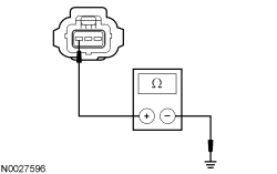 | Yes
GO to O10 . No REPAIR the circuit. TEST the system for normal operation. |
| O10 CHECK THE BRAKE FLUID LEVEL SWITCH | |
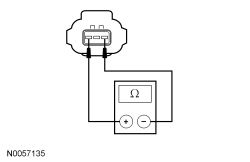 | Yes
GO to O11 . No INSTALL a new brake fluid level switch. TEST the system for normal operation. |
| O11 CHECK FOR CORRECT SJB OPERATION | |
| Yes
INSTALL a new SJB . REFER to Section 419-10 . TEST the system for normal operation. No The system is operating correctly at this time. The concern may have been caused by a loose or corroded connector. |
Pinpoint Test P: The Brake Warning Indicator is Always On
Diagnostics in this manual assume a certain skill level and knowledge of Ford-specific diagnostic practices. Refer to Diagnostic Methods in Section 100-00 for information regarding these diagnostic practices.
Refer to Wiring Diagrams Cell 60 , Instrument Cluster for schematic and connector information.
The Instrument Panel Cluster (IPC) uses 3 basic messaged inputs to control the brake warning indicator. The first 2 are the parking brake warning indicator switch and brake fluid level switch. The third is for the Electronic Brake Distribution (EBD), controlled by the ABS. The parking brake warning indicator switch and the brake fluid level switch status are sent from the Smart Junction Box (SJB) over the Medium Speed Controller Area Network (MS-CAN) communication bus. The EBD message is sent from the ABS module over the High Speed Controller Area Network (HS-CAN) communication bus lines. The parking brake warning indicator switch and brake fluid level switch are both hardwired to the SJB . The parking brake warning indicator switch and the brake fluid level use an external ground circuit.
The SJB provides a reference voltage to both the parking brake warning indicator switch and the brake fluid level switch. When the parking brake is applied, the parking brake warning indicator switch closes to ground, pulling the brake fluid level input circuit low. When a low brake fluid level condition exists, the low brake fluid level switch closes to ground pulling the brake fluid level input circuit low. The SJB monitors the parking brake and the brake fluid level inputs, sending the IPC a message to turn the brake warning indicator on when the parking brake is applied, when the brake fluid level is low, or if the SJB detects an open in the brake fluid level signal or return circuits. When the ABS module detects a base brake system concern or other ABS-related concerns that affect the EBD function, the ABS module sends a message to the IPC to illuminate both the ABS warning indicator and the brake warning indicator.
If the brake fluid level or parking brake status messages are missing for more than 5 seconds, the IPC sets DTC U0140:87 and defaults the brake warning indicator on. If the IPC does not receive the ABS status message or the EBD message from the ABS module for more than 5 seconds, the IPC sets DTC U0121:87 and defaults the ABS warning indicator on.
NOTE: If DTC U0140:87 is set in the IPC , other symptoms can also be present such as Tire Pressure Monitoring System (TPMS), instrument panel backlighting, and door ajar indication.
NOTE: Whenever the IPC receives an EBD message from the ABS module, the IPC illuminates both the brake warning indicator and the ABS warning indicator simultaneously.
This pinpoint test is intended to diagnose the following:
NOTICE: Use the correct probe adapter(s) when making measurements. Failure to use the correct probe adapter(s) may damage the connector.
| Test Step | Result / Action to Take |
|---|---|
| P1 CARRY OUT THE IPC INDICATOR LAMP CONTROL ACTIVE COMMAND USING THE SCAN TOOL | |
| Yes
GO to P2 . No INSTALL a new IPC . REFER to Instrument Panel Cluster (IPC) in this section. TEST the system for normal operation. |
| P2 RETRIEVE THE RECORDED DTCs FROM THE IPC SELF-TEST | |
| Yes
For DTC U0140:87, GO to Pinpoint Test AV . For DTC U0121:87, GO to Pinpoint Test AT . For all other DTCs, REFER to DTC Charts in this section. No GO to P3 . |
| P3 RETRIEVE THE RECORDED DTCs FROM THE ABS MODULE SELF-TEST | |
| Yes
REFER to Section 206-09 . No GO to P4 . |
| P4 RETRIEVE THE RECORDED DTCs FROM THE SJB SELF-TEST | |
| Yes
GO to P5 . No GO to P8 . |
| P5 CHECK THE PARKING BRAKE WARNING INDICATOR SWITCH PID | |
| Yes
GO to P12 . No GO to P6 . |
| P6 CHECK THE PARKING BRAKE WARNING INDICATOR SWITCH | |
| Yes
INSTALL a new parking brake warning indicator switch. CLEAR the DTCs. REPEAT the self-test. No GO to P7 . |
| P7 CHECK THE PARKING BRAKE INPUT CIRCUIT FOR A SHORT TO GROUND | |
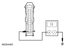 | Yes
GO to P12 . No REPAIR the circuit. CLEAR the DTCs. REPEAT the self-test. |
| P8 CHECK THE BRAKE WARNING INDICATOR USING THE FLUID LEVEL SWITCH | |
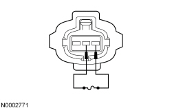 | Yes
REMOVE the jumper wire. INSTALL a new brake fluid level switch. REPEAT the self-test. CLEAR the DTCs. No REMOVE the jumper wire. GO to P9 . |
| P9 CHECK BRAKE FLUID LEVEL INPUT CIRCUIT FOR AN OPEN | |
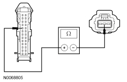 | Yes
GO to P10 . No REPAIR the circuit. TEST the system for normal operation. |
| P10 CHECK BRAKE FLUID LEVEL SIGNAL RETURN CIRCUIT OR AN OPEN | |
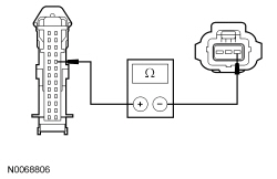 | Yes
GO to P11 . No REPAIR the circuit. TEST the system for normal operation. |
| P11 CHECK BRAKE FLUID LEVEL INPUT AND SIGNAL RETURN CIRCUITS FOR A SHORT TO GROUND | |
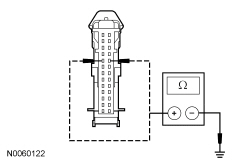 | Yes
GO to P12 . No REPAIR the circuit in question. TEST the system for normal operation. |
| P12 CHECK FOR CORRECT SJB OPERATION | |
| Yes
INSTALL a new SJB . REFER to Section 419-10 . TEST the system for normal operation. No The system is operating correctly at this time. The concern may have been caused by a loose or corroded connector. |
Pinpoint Test Q: The ABS Warning Indicator Is Never/Always On
Diagnostics in this manual assume a certain skill level and knowledge of Ford-specific diagnostic practices. Refer to Diagnostic Methods in Section 100-00 for information regarding these diagnostic practices.
The ABS module provides ABS status to the Instrument Panel Cluster (IPC) over the High Speed Controller Area Network (HS-CAN) communication bus. If a fault condition exists in the ABS, the ABS module sends the IPC a command to either flash the ABS warning indicator or to turn it on. If the ABS status message is missing for less than 5 seconds, the IPC defaults the ABS warning indicator to the last on/off state, based upon the last known good ABS status message received. If the ABS status message is missing for more than 5 seconds, the IPC sets DTC U0121:87 and defaults the ABS warning indicator on.
This pinpoint test is intended to diagnose the following:
| Test Step | Result / Action to Take |
|---|---|
| Q1 CARRY OUT THE IPC INDICATOR LAMP CONTROL ACTIVE COMMAND USING THE SCAN TOOL | |
| Yes
GO to Q2 . No INSTALL a new IPC . REFER to Instrument Panel Cluster (IPC) in this section. TEST the system for normal operation. |
| Q2 RETRIEVE THE RECORDED DTCs FROM THE IPC SELF-TEST | |
| Yes
For DTC U0121:87, GO to Pinpoint Test AT . For all other DTCs, REFER to DTC Charts in this section. No GO to Q3 . |
| Q3 RETRIEVE THE RECORDED DTCs FROM THE ABS MODULE SELF-TEST | |
| Yes
REFER to Section 206-09 . No INSTALL a new ABS module. REFER to Section 206-09 . TEST the system for normal operation. |
Pinpoint Test R: The Air Bag Warning Indicator Is Never/Always On
Diagnostics in this manual assume a certain skill level and knowledge of Ford-specific diagnostic practices. Refer to Diagnostic Methods in Section 100-00 for information regarding these diagnostic practices.
The Instrument Panel Cluster (IPC) receives the Supplemental Restraint System (SRS) status from the Restraints Control Module (RCM) over the High Speed Controller Area Network (HS-CAN) communication bus. If a SRS concern is detected, the RCM sets a DTC and sends a message to the IPC to turn on the air bag warning indicator.
If the SRS status message is missing for less than 5 seconds, the IPC defaults the air bag warning indicator to the last on/off state, based upon the last known good SRS status message received.
If the SRS status message is missing for more than 5 seconds, the IPC sets DTC U0151:87 and defaults the air bag warning indicator on.
This pinpoint test is intended to diagnose the following:
| Test Step | Result / Action to Take |
|---|---|
| R1 CARRY OUT THE IPC AIR BAG WARNING INDICATOR ACTIVE COMMAND USING THE SCAN TOOL | |
| Yes
GO to R2 . No INSTALL a new IPC . REFER to Instrument Panel Cluster (IPC) in this section. TEST the system for normal operation. |
| R2 RETRIEVE THE RECORDED DTCs FROM THE RCM SELF-TEST | |
| Yes
REFER to Section 501-20B . No GO to R3 . |
| R3 RETRIEVE THE RECORDED DTCs FROM THE IPC SELF-TEST | |
| Yes
For DTC U0151:87, GO to Pinpoint Test AX . For all other DTCs, REFER to DTC Charts in this section. No INSTALL a new RCM . REFER to Section 501-20B . TEST the system for normal operation. |
Pinpoint Test S: The Safety Belt Warning Indicator Is Never/Always On
Diagnostics in this manual assume a certain skill level and knowledge of Ford-specific diagnostic practices. Refer to Diagnostic Methods in Section 100-00 for information regarding these diagnostic practices.
The Restraints Control Module (RCM) monitors the safety belt position through the safety belt buckle switch. The RCM provides the safety belt buckle status to the Instrument Panel Cluster (IPC) over the High Speed Controller Area Network (HS-CAN) communication bus.
If the IPC does not receive the safety belt buckle switch status from the RCM for less than 5 seconds, the IPC defaults the safety belt warning indicator to the last on/off state, based upon the last known good safety belt status message received.
If the IPC does not receive the safety belt buckle switch status from the RCM for more than 5 seconds, the IPC sets DTC U0151:87 and defaults the safety belt warning indicator off.
This pinpoint test is intended to diagnose the following:
| Test Step | Result / Action to Take |
|---|---|
| S1 RETRIEVE THE RECORDED DTCs FROM THE RCM SELF-TEST | |
| Yes
REFER to Section 501-20B . No GO to S2 . |
| S2 RETRIEVE THE RECORDED DTCs FROM THE IPC SELF-TEST | |
| Yes
GO to Pinpoint Test AX . No GO to S3 . |
| S3 CARRY OUT THE IPC INDICATOR LAMP CONTROL ACTIVE COMMAND USING THE SCAN TOOL | |
| Yes
INSTALL a new RCM . REFER to Section 501-20B . TEST the system for normal operation. No INSTALL a new IPC . REFER to Instrument Panel Cluster (IPC) in this section. TEST the system for normal operation. |
Pinpoint Test T: The Door Ajar Warning Indicator Is Never/Always On
Diagnostics in this manual assume a certain skill level and knowledge of Ford-specific diagnostic practices. Refer to Diagnostic Methods in Section 100-00 for information regarding these diagnostic practices.
The Instrument Panel Cluster (IPC) receives the door ajar status for the LH and RH front door from the Smart Junction Box (SJB) over the Medium Speed Controller Area Network (MS-CAN) communication bus. When the IPC receives a message from the SJB that one or more doors are open or ajar, the IPC turns on the door ajar warning indicator.
If the door ajar status message is missing for less than 5 seconds, the door ajar warning indicator remains in the last indication mode (on or off) based upon the last known good message received.
If the door ajar status message is missing for more than 5 seconds, the IPC sets DTC U0140:87 and defaults the door ajar warning indicator on.
NOTE: If DTC U0140:87 is set in the SJB , other symptoms can also be present in the IPC such as high beam indicator, RH/LH turn indicators, instrument panel backlighting and Tire Pressure Monitoring System (TPMS).
This pinpoint test is intended to diagnose the following:
NOTICE: Use the correct probe adapter(s) when making measurements. Failure to use the correct probe adapter(s) may damage the connector.
| Test Step | Result / Action to Take |
|---|---|
| T1 CHECK THE INTERIOR LIGHTING OPERATION | |
| Yes
GO to T2 . No REFER to Section 417-02 . |
| T2 RETRIEVE THE RECORDED DTCs FROM THE CONTINUOUS IPC SELF-TEST | |
| Yes
GO to Pinpoint Test AV . No GO to T3 . |
| T3 RETRIEVE THE RECORDED DTCs FROM THE SJB SELF-TEST | |
| Yes
REFER to Section 419-10 . No GO to T4 . |
| T4 CARRY OUT THE IPC DOOR AJAR WARNING INDICATOR ACTIVE COMMAND USING THE SCAN TOOL | |
| Yes
INSTALL a new SJB . REFER to Section 419-10 . TEST the system for normal operation. No INSTALL a new IPC . REFER to Instrument Panel Cluster (IPC) in this section. TEST the system for normal operation. |
Pinpoint Test U: The Malfunction Indicator Lamp (MIL) Is Never/Always On
Diagnostics in this manual assume a certain skill level and knowledge of Ford-specific diagnostic practices. Refer to Diagnostic Methods in Section 100-00 for information regarding these diagnostic practices.
The Malfunction Indicator Lamp (MIL) is controlled by the Instrument Panel Cluster (IPC) using data sent from the PCM over the High Speed Controller Area Network (HS-CAN) communication bus. If the MIL status message is missing for less than 5 seconds, the MIL remains in the last on or off state based upon the last known good charging system status message received. If the MIL status message is missing for more than 5 seconds, the IPC sets DTC U0100:87 in continuous memory and defaults the MIL on. If the MIL message is deemed invalid for longer than 5 seconds, the IPC defaults the MIL on.
NOTE: If DTC U0100:87 is set in the IPC , other observable symptoms can be an inoperative speedometer, tachometer or odometer.
This pinpoint test is intended to diagnose the following:
| Test Step | Result / Action to Take |
|---|---|
| U1 CARRY OUT THE IPC WARNING LAMPS AND CHIME ACTIVE COMMAND USING THE SCAN TOOL | |
| Yes
GO to U2 . No INSTALL a new IPC . REFER to Instrument Panel Cluster (IPC) in this section. TEST the system for normal operation. |
| U2 RETRIEVE THE RECORDED PCM DTCs FROM THE KOEO SELF-TEST | |
| Yes
DIAGNOSE all PCM DTCs first. REFER to the Powertrain Control/Emissions Diagnosis (PC/ED) manual. No GO to U3 . |
| U3 RETRIEVE THE RECORDED DTCs FROM THE IPC SELF-TEST | |
| Yes
For DTC U0100:87, GO to Pinpoint Test AS . For all other DTCs, REFER to DTC Charts in this section. No INSTALL a new PCM. REFER to Section 303-14 . TEST the system for normal operation. |
Pinpoint Test V: The Powertrain Malfunction (Wrench) Warning Indicator Is Never/Always On (Base IPC )
Diagnostics in this manual assume a certain skill level and knowledge of Ford-specific diagnostic practices. Refer to Diagnostic Methods in Section 100-00 for information regarding these diagnostic practices.
The Instrument Panel Cluster (IPC) receives the powertrain malfunction data from the PCM over the High Speed Controller Area Network (HS-CAN) communication bus. The PCM monitors the Electronic Throttle Control (ETC) system status and transmission status. When a fault condition exists in the ETC system or in the transmission, the PCM provides the IPC with a message to turn the powertrain malfunction (wrench) indicator on.
If the ETC or transmission message is missing for less than 5 seconds, the IPC defaults the powertrain malfunction (wrench) indicator to the last on/off state, based upon the last known good ETC or transmission message received.
If the ETC or transmission message is missing for 5 seconds or longer, the IPC sets DTC U0100:87 and defaults the powertrain malfunction (wrench) warning indicator on.
NOTE: If U0100:87 is set in the IPC , other symptoms can also be present such as an inoperative speedometer, tachometer or temperature gauge.
This pinpoint test is intended to diagnose the following:
| Test Step | Result / Action to Take |
|---|---|
| V1 CHECK THE POWERTRAIN MALFUNCTION (WRENCH) OFF INDICATOR USING THE SCAN TOOL | |
| Yes
GO to V2 . No INSTALL a new IPC . REFER to Instrument Panel Cluster (IPC) in this section. TEST the system for normal operation. |
| V2 RETRIEVE THE RECORDED PCM DTCs FROM THE KOEO SELF-TEST | |
| Yes
DIAGNOSE all PCM DTCs first. REFER to the Powertrain Control/Emissions Diagnosis (PC/ED) manual. No GO to V3 . |
| V3 RETRIEVE THE RECORDED DTCs FROM THE IPC SELF-TEST | |
| Yes
For DTC U0100:87, GO to Pinpoint Test AS . For all other DTCs, REFER to DTC Charts in this section. No INSTALL a new PCM. REFER to Section 303-14 . TEST the system for normal operation. |
Pinpoint Test W: The Grade Assist Indicator is Never/Always On
Diagnostics in this manual assume a certain skill level and knowledge of Ford-specific diagnostic practices. Refer to Diagnostic Methods in Section 100-00 for information regarding these diagnostic practices.
The Instrument Panel Cluster (IPC) receives the grade assist status from the Transmission Control Module (TCM) (part of the PCM) over the High Speed Controller Area Network (HS-CAN) communication bus. When the grade assist function is selected on, the TCM sends a message to the IPC to illuminate the grade assist indicator.
If the grade assist message is missing for less than 5 seconds, the grade assist indicator remains in the last on/off state, based upon the last known good grade assist message received.
If the grade assist off message is missing for more than 5 seconds, DTC U0100:87 sets in continuous memory and defaults the grade assist indicator off.
This pinpoint test is intended to diagnose the following:
| Test Step | Result / Action to Take |
|---|---|
| W1 CHECK THE OPERATION OF THE GRADE ASSIST FUNCTION | |
| Yes
GO to W2 . No REFER to Section 307-01 . |
| W2 CARRY OUT THE IPC INDICATOR LAMP CONTROL ACTIVE COMMAND USING THE SCAN TOOL | |
| Yes
GO to W3 . No INSTALL a new IPC . REFER to Instrument Panel Cluster (IPC) in this section. TEST the system for normal operation. |
| W3 RETRIEVE THE RECORDED DTCs FROM THE IPC SELF-TEST | |
| Yes
GO to Pinpoint Test AS . No GO to W4 . |
| W4 RETRIEVE THE RECORDED TCM DTCs FROM THE SELF-TEST | |
| Yes
REFER to the DTC Chart in Section 307-01 . No INSTALL a new PCM. REFER to Section 303-14 . TEST the system for normal operation. |
Pinpoint Test X: The Charging System Warning Indicator Is Never/Always On
Diagnostics in this manual assume a certain skill level and knowledge of Ford-specific diagnostic practices. Refer to Diagnostic Methods in Section 100-00 for information regarding these diagnostic practices.
The charging system indicator is controlled by the Instrument Panel Cluster (IPC) based upon data received from the PCM over the High Speed Controller Area Network (HS-CAN) communication bus.
If the charging system message is missing for less than 5 seconds, the charging system indicator remains in the last indication mode (on or off). If the charging system message is missing for more than 5 seconds, the IPC sets DTC U0100:87 in continuous memory and defaults the charging system warning indicator on.
NOTE: If DTC U0100:87 is set in the IPC , other observable symptoms can be an inoperative speedometer, tachometer or odometer.
This pinpoint test is intended to diagnose the following:
| Test Step | Result / Action to Take |
|---|---|
| X1 CARRY OUT THE IPC INDICATOR LAMP CONTROL ACTIVE COMMAND USING THE SCAN TOOL | |
| Yes
GO to X2 . No INSTALL a new IPC . REFER to Instrument Panel Cluster (IPC) in this section. TEST the system for normal operation. |
| X2 RETRIEVE THE RECORDED PCM DTCs FROM THE KOEO SELF-TEST | |
| Yes
REFER to Section 414-00 . No GO to X3 . |
| X3 CHECK THE CHARGING SYSTEM OPERATION | |
| Yes
GO to X4 . No REFER to Section 414-00 . |
| X4 RETRIEVE THE RECORDED DTCs FROM THE IPC SELF-TEST | |
| Yes
GO to Pinpoint Test AS . No INSTALL a new PCM. REFER to Section 303-14 . TEST the system for normal operation. |
Pinpoint Test Y: The High Beam Indicator Is Never/Always On
Diagnostics in this manual assume a certain skill level and knowledge of Ford-specific diagnostic practices. Refer to Diagnostic Methods in Section 100-00 for information regarding these diagnostic practices.
When the multifunction switch is in the high beam position, a message is sent to the Instrument Panel Cluster (IPC) from the Smart Junction Box (SJB) over the Medium Speed Controller Area Network (MS-CAN) communication bus. Upon receipt of the high beam on message, the IPC illuminates the high beam indicator.
If the high beam status message is missing from the SJB for less than 5 seconds, the IPC defaults the high beam indicator to the last on/off state, based upon the last known good high beam status message received.
If the high beam status message is missing for more than 5 seconds, the IPC sets DTC U0140:87 and defaults the high beam indicator off.
This pinpoint test is intended to diagnose the following:
| Test Step | Result / Action to Take |
|---|---|
| Y1 DETERMINE THE FAULT CONDITION | |
| Yes
GO to Y4 . No LEAVE the headlamps in the HIGH BEAM position. GO to Y2 . |
| Y2 CHECK THE HIGH BEAM HEADLAMPS OPERATION | |
| Yes
GO to Y3 . No REFER to Section 417-01 . |
| Y3 CARRY OUT THE IPC INDICATOR LAMP CONTROL ACTIVE COMMAND USING THE SCAN TOOL | |
| Yes
GO to Y4 . No INSTALL a new IPC . REFER to Instrument Panel Cluster (IPC) in this section. TEST the system for normal operation. |
| Y4 RETRIEVE THE RECORDED DTCs FROM THE IPC SELF-TEST | |
| Yes
For DTC U0140:87, GO to Pinpoint Test AV . For all other DTCs, REFER to DTC Charts in this section. No INSTALL a new SJB . REFER to Section 419-10 . TEST the system for normal operation. |
Pinpoint Test Z: The LH/RH Turn Indicator Is Never/Always On
Diagnostics in this manual assume a certain skill level and knowledge of Ford-specific diagnostic practices. Refer to Diagnostic Methods in Section 100-00 for information regarding these diagnostic practices.
When the multifunction switch is in the LH or RH TURN position a message is sent to the Instrument Panel Cluster (IPC) from the Smart Junction Box (SJB) over the Medium Speed Controller Area Network (MS-CAN) communication bus. Upon receipt of the LH/RH turn message, the IPC flashes the LH or RH turn signal indicator on and off.
This pinpoint test is intended to diagnose the following:
| Test Step | Result / Action to Take |
|---|---|
| Z1 CHECK THE LH OR RH TURN SIGNAL LAMPS OPERATION | |
| Yes
GO to Z2 . No REFER to Section 417-01 . |
| Z2 CARRY OUT THE IPC INDICATOR LAMP CONTROL ACTIVE COMMAND USING THE SCAN TOOL | |
| Yes
GO to Z3 . No INSTALL a new IPC . REFER to Instrument Panel Cluster (IPC) in this section. TEST the system for normal operation. |
| Z3 RETRIEVE THE RECORDED DTCs FROM THE IPC SELF-TEST | |
| Yes
For DTC U0140:87, GO to Pinpoint Test AV . For all other DTCs, REFER to DTC Charts in this section. No INSTALL a new SJB . REFER to Section 419-10 . TEST the system for normal operation. |
Pinpoint Test AA: The Cruise Control Indicator Is Never/Always On
Diagnostics in this manual assume a certain skill level and knowledge of Ford-specific diagnostic practices. Refer to Diagnostic Methods in Section 100-00 for information regarding these diagnostic practices.
The Instrument Panel Cluster (IPC) receives the cruise control signal from the PCM over the High Speed Controller Area Network (HS-CAN) communication bus. When the cruise control is engaged, the PCM sends a message to the IPC to illuminate the cruise control indicator. If the cruise control message is missing for less than 5 seconds, the IPC defaults the cruise control indicator to the last on/off state, based upon the last known good cruise control message received.
If the cruise control message is missing for more than 5 seconds, the IPC sets DTC U0100:87 in continuous memory and defaults the cruise control indicator off.
NOTE: If DTC U0100:87 is set in the IPC , other observable symptoms can be an inoperative speedometer, tachometer or odometer.
This pinpoint test is intended to diagnose the following:
| Test Step | Result / Action to Take |
|---|---|
| AA1 CHECK THE CRUISE CONTROL OPERATION | |
| Yes
GO to AA2 . No REFER to Section 419-03 . |
| AA2 CARRY OUT THE IPC INDICATOR LAMP CONTROL ACTIVE COMMAND USING THE SCAN TOOL | |
| Yes
GO to AA3 . No INSTALL a new IPC . REFER to Instrument Panel Cluster (IPC) in this section. TEST the system for normal operation. |
| AA3 RETRIEVE THE RECORDED DTCs FROM THE IPC SELF-TEST | |
| Yes
For DTC U0100:87, GO to Pinpoint Test AS . For all other DTCs, REFER to DTC Charts in this section. No INSTALL a new PCM. REFER to Section 303-14 . TEST the system for normal operation. |
Pinpoint Test AB: The Stability/Traction Control Indicator (Sliding Car Icon) Is Never/Always On
Diagnostics in this manual assume a certain skill level and knowledge of Ford-specific diagnostic practices. Refer to Diagnostic Methods in Section 100-00 for information regarding these diagnostic practices.
The Instrument Panel Cluster (IPC) receives the stability/traction control data from the ABS module over the High Speed Controller Area Network (HS-CAN) communication bus. The stability/traction control indicator (sliding car icon) flashes when the vehicle stability/traction control is in active mode or is being controlled by the ABS module. The stability/traction control indicator (sliding car icon) turns on steady if a fault condition exists in the system. The IPC monitors the stability/traction control message from the ABS module and either flashes the stability/traction control indicator (sliding car icon) or turns it on steady depending on the condition. If the stability/traction control message is missing for more than 5 seconds, the IPC sets DTC U0121:87 in continuous memory and defaults the stability/traction control indicator (sliding car icon) on.
This pinpoint test is intended to diagnose the following:
| Test Step | Result / Action to Take |
|---|---|
| AB1 RETRIEVE THE RECORDED DTCs FROM THE IPC SELF-TEST | |
| Yes
For DTC U0121:87, GO to Pinpoint Test AT . For all other DTCs, REFER to DTC Charts in this section. No GO to AB2 . |
| AB2 RETRIEVE THE RECORDED DTCs FROM THE ABS MODULE SELF-TEST | |
| Yes
REFER to Section 206-09 . No GO to AB3 . |
| AB3 CARRY OUT THE IPC INDICATOR LAMP CONTROL ACTIVE COMMAND USING THE SCAN TOOL | |
| Yes
INSTALL a new ABS module. REFER to Section 206-09 . TEST the system for normal operation. No INSTALL a new IPC . REFER to Instrument Panel Cluster (IPC) in this section. TEST the system for normal operation. |
Pinpoint Test AC: The Stability/Traction Control Disabled Indicator (Sliding Car OFF Icon) Is Never/Always On
Diagnostics in this manual assume a certain skill level and knowledge of Ford-specific diagnostic practices. Refer to Diagnostic Methods in Section 100-00 for information regarding these diagnostic practices.
The traction control switch is hardwired to the Instrument Panel Cluster (IPC). When the traction control switch is pressed, the IPC sends a message to the ABS module over the High Speed Controller Area Network (HS-CAN) communication bus. The ABS module either disables or enables the stability/traction control and sends a message back to the IPC to turn on or off the stability/traction control disabled indicator (sliding car OFF icon) based upon the system state. If the traction control switch state message is missing for less than 5 seconds, the stability/traction control off indicator remains in the last indication mode (on or off) based upon the last known good message received. If the traction control switch state message is missing for more than 5 seconds, the IPC sets DTC U0121:87 in continuous memory and defaults the stability/traction control disabled indicator (sliding car OFF icon) off.
NOTE: When a MyKey® programmed key is in use and the AdvanceTrac® on feature is configured always on, the stability/traction control system cannot be disabled and the stability/traction control indicator does not turn on when the traction control disable button is pressed. The stability/traction control indicator still functions normally to indicate a stability/traction control system fault and a stability/traction control active event.
This pinpoint test is intended to diagnose the following:
| Test Step | Result / Action to Take |
|---|---|
| AC1 CARRY OUT THE IPC INDICATOR LAMP CONTROL ACTIVE COMMAND USING THE SCAN TOOL | |
| Yes
GO to AC2 . No INSTALL a new IPC . REFER to Instrument Panel Cluster (IPC) in this section. TEST the system for normal operation. |
| AC2 CHECK FOR THE KEY TYPE | |
| Yes
GO to AC3 . No If the MyKey® AdvanceTrac® on feature is configured always on, the system is normal. The stability/traction control system cannot be disabled when the AdvanceTrac® on feature is configured always on. If the MyKey® AdvanceTrac® on feature is not configured always on, GO to AC3 . |
| AC3 CHECK THE TRACTION CONTROL INPUT TO THE IPC | |
| Yes
GO to AC4 . No REFER to Section 206-09 to diagnose the stability/traction control system cannot be disabled. |
| AC4 RETRIEVE THE RECORDED DTCs FROM THE IPC SELF-TEST | |
| Yes
For DTC U0121:87, GO to Pinpoint Test AT . For all other DTCs, REFER to DTC Charts in this section. No GO to AC5 . |
| AC5 RETRIEVE THE RECORDED DTCs FROM THE ABS MODULE SELF-TEST | |
| Yes
REFER to Section 206-09 . No INSTALL a new ABS module. REFER to Section 206-09 . TEST the system for normal operation. |
Pinpoint Test AD: The Low Fuel Warning Indicator Is Never/Always On
Diagnostics in this manual assume a certain skill level and knowledge of Ford-specific diagnostic practices. Refer to Diagnostic Methods in Section 100-00 for information regarding these diagnostic practices.
The low fuel indicator turns on when the fuel level reaches a predetermined level, approximately 120 km (75 miles) (with a MyKey® programmed key) or 80 km (50 miles) (with an administrator key). The low fuel level warning indicator and fuel gauge are controlled by the Instrument Panel Cluster (IPC) based on the fuel level data provided by the fuel pump module.
This pinpoint test is intended to diagnose the following:
| Test Step | Result / Action to Take |
|---|---|
| AD1 CHECK THE FUEL GAUGE FOR CORRECT OPERATION | |
| Yes
GO to AD2 . No GO to Pinpoint Test B . |
| AD2 CARRY OUT THE IPC INDICATOR LAMP CONTROL ACTIVE COMMAND USING THE SCAN TOOL | |
| Yes
GO to AD3 . No INSTALL a new IPC . REFER to Instrument Panel Cluster (IPC) in this section. TEST the system for normal operation. |
| AD3 CHECK THE DTE REMAINING MILEAGE DISPLAYED | |
| Yes
INSTALL a new IPC . REFER to Instrument Panel Cluster (IPC) in this section. TEST the system for normal operation. No The system is operating normally at this time. The fuel level must be below one-eighth tank before the low fuel indicator is turned on. |
Pinpoint Test AE: The Performance Shift Indicator Is Never/Always On (GT500)
Diagnostics in this manual assume a certain skill level and knowledge of Ford-specific diagnostic practices. Refer to Diagnostic Methods in Section 100-00 for information regarding these diagnostic practices.
The performance shift indicator shares the SVT logo on the tachometer. The performance shift indicator is configurable on or off and uses engine rpm to determine when to illuminate. The SVT logo is normally backlit in red when the performance indicator is configured off. When the performance shift indicator is configured on, the SVT logo red backlighting is turned off. When a preset engine rpm is reached, the SVT logo illuminates orange to alert the driver of the selected shift point. The performance shift indicator can be configured on or off through the message center.
The performance shift indicator receives the engine rpm status from the PCM over the High Speed Controller Area Network (HS-CAN) communication bus lines. When the engine rpm is equal to the preset (configured) shift rpm, the Instrument Panel Cluster (IPC) turns on the performance shift indicator.
This pinpoint test is intended to diagnose the following:
| Test Step | Result / Action to Take |
|---|---|
| AE1 CHECK THE PERFORMANCE SHIFT CONFIGURATION | |
| Yes
GO to AE2 . No CONFIGURE the performance shift indicator on. REFER to Message Center Configuration or the Owner's Literature for additional information. TEST the system for normal operation. |
| AE2 RETRIEVE THE RECORDED DTCs FROM BOTH THE CONTINUOUS AND ON-DEMAND PCM SELF-TESTS | |
| Yes
REFER to the Powertrain Control/Emissions Diagnosis (PC/ED) manual. No GO to AE3 . |
| AE3 CARRY OUT THE IPC INDICATOR LAMP CONTROL ACTIVE COMMAND | |
| Yes
INSTALL a new PCM. REFER to Section 303-14 . TEST the system for normal operation. No INSTALL a new IPC . REFER to Instrument Panel Cluster (IPC) in this section. TEST the system for normal operation. |
Pinpoint Test AF: The Shift Indicator Is Never/Always On (GT500)
Diagnostics in this manual assume a certain skill level and knowledge of Ford-specific diagnostic practices. Refer to Diagnostic Methods in Section 100-00 for information regarding these diagnostic practices.
The shift indicator is used to inform the driver of shift points that provide the highest fuel economy. The shift indicator is controlled by the Instrument Panel Cluster (IPC) based upon a shift message sent from the PCM over the High Speed Controller Area Network (HS-CAN) communication bus lines.
NOTE: If DTC U0100:87 is set in the IPC , other observable symptoms can be an inoperative speedometer, tachometer or odometer.
This pinpoint test is intended to diagnose the following:
| Test Step | Result / Action to Take |
|---|---|
| AF1 RETRIEVE THE RECORDED DTCs FROM BOTH THE CONTINUOUS AND ON-DEMAND PCM SELF-TESTS | |
| Yes
REFER to the Powertrain Control/Emissions Diagnosis (PC/ED) manual. No GO to AF2 . |
| AF2 RETRIEVE THE RECORDED DTCs FROM THE IPC SELF-TEST | |
| Yes
For DTC U0100:87, GO to Pinpoint Test AS . For all other DTCs, REFER to DTC Charts in this section. No GO to AF3 . |
| AF3 CARRY OUT THE IPC INDICATOR LAMP CONTROL ACTIVE COMMAND | |
| Yes
INSTALL a new PCM. REFER to Section 303-14 . TEST the system for normal operation. No INSTALL a new IPC . REFER to Instrument Panel Cluster (IPC) in this section. TEST the system for normal operation. |
Pinpoint Test AG: The Tire Pressure Monitoring System (TPMS) Warning Indicator Is Never/Always On
Diagnostics in this manual assume a certain skill level and knowledge of Ford-specific diagnostic practices. Refer to Diagnostic Methods in Section 100-00 for information regarding these diagnostic practices.
The Instrument Panel Cluster (IPC) receives the Tire Pressure Monitoring System (TPMS) messages from the Smart Junction Box (SJB) over the Medium Speed Controller Area Network (MS-CAN) communication bus. If the SJB determines that the tire pressure has exceeded the low tire pressure limits, a message is sent to the IPC to turn the TPMS warning indicator on. If a TPMS fault condition exists, the SJB sends a message to the IPC to flash the TPMS warning indicator for 75 seconds then the IPC turns the indicator on steady. If the TPMS is in the TPMS sensor training mode, the SJB sends a command to the IPC to flash the TPMS warning indicator throughout the procedure. If the TPMS status message is missing or deemed invalid for less than 5 seconds, the IPC defaults the TPMS warning indicator to the last setting (on or off), based upon the last known good message received. If the TPMS status message is missing for more than 5 seconds, the TPMS warning indicator flashes for approximately 75 seconds then turns the indicator on steady. If the message is invalid for more than 5 seconds, the IPC sets DTC U0422:86 and flashes the TPMS warning indicator for approximately 75 seconds then turns the indicator on steady.
This pinpoint test is intended to diagnose the following:
| Test Step | Result / Action to Take |
|---|---|
| AG1 CHECK THE TIRE PRESSURE | |
| Yes
GO to AG2 . No CORRECT the tire pressures. TEST the system for normal operation. |
| AG2 CARRY OUT THE IPC INDICATOR LAMP CONTROL ACTIVE COMMAND USING THE SCAN TOOL | |
| Yes
GO to AG3 . No INSTALL a new IPC . REFER to Instrument Panel Cluster (IPC) in this section. TEST the system for normal operation. |
| AG3 RETRIEVE THE RECORDED DTCs FROM THE IPC SELF-TEST | |
| Yes
For DTC U0422:86, RETRIEVE and REPAIR all non-network DTCs in the other modules on the network. REFER to Section 419-10 . TEST the system for normal operation. For all other DTCs, REFER to DTC Charts in this section. No GO to AG4 . |
| AG4 RETRIEVE THE RECORDED DTCs FROM THE SJB SELF-TEST | |
| Yes
REFER to Section 419-10 . No INSTALL a new SJB . REFER to Section 419-10 . TEST the system for normal operation. |
Pinpoint Test AH: The Anti-Theft Indicator Is Never/Always On
Diagnostics in this manual assume a certain skill level and knowledge of Ford-specific diagnostic practices. Refer to Diagnostic Methods in Section 100-00 for information regarding these diagnostic practices.
The Instrument Panel Cluster (IPC) interacts with the PCM and controls the Passive Anti-Theft System (PATS) function. The IPC controls the anti-theft indicator based upon the status of the PATS .
The anti-theft indicator proves out for 3 seconds when the key is turned to the ON or START position. If there is a PATS concern, the anti-theft indicator either flashes rapidly or glows steadily (for more than 3 seconds) when the ignition is switched to the ON or the START mode. The PATS also flashes the anti-theft indicator every 2 seconds at ignition off to act as a visual theft deterrent for all vehicles.
This pinpoint test is intended to diagnose the following:
| Test Step | Result / Action to Take |
|---|---|
| AH1 CARRY OUT THE IPC ANTI-THEFT INDICATOR ACTIVE COMMAND USING THE SCAN TOOL | |
| Yes
GO to AH2 . No INSTALL a new IPC . REFER to Instrument Panel Cluster (IPC) in this section. TEST the system for normal operation. |
| AH2 RETRIEVE THE RECORDED DTCs FROM THE CONTINUOUS IPC SELF-TEST | |
| Yes
REFER to Section 419-01B . No INSTALL a new IPC . REFER to Instrument Panel Cluster (IPC) in this section. TEST the system for normal operation. |
Pinpoint Test AI: The Message Center Is Not Operating Correctly
Diagnostics in this manual assume a certain skill level and knowledge of Ford-specific diagnostic practices. Refer to Diagnostic Methods in Section 100-00 for information regarding these diagnostic practices.
Refer to Wiring Diagrams Cell 60 , Instrument Cluster for schematic and connector information.
The message center functionality is controlled through the message center switch (part of the LH steering wheel switch), which is hardwired to the Instrument Panel Cluster (IPC) through input and return circuits. There are 3 message center switch buttons (base IPC ) or 5 message center switch buttons (optional and GT500 IPC ). Each button operates a unique switch within the message center switch portion of the LH steering wheel switch assembly using a different resistance value associated with each specific button. The IPC sends out a reference voltage to the LH steering wheel switch on the input circuit and monitors the voltage drop when a message center switch button is pressed. The voltage drop varies depending upon the resistance of the specific button pressed, providing indication to the IPC , which switch is pressed.
| DTC Description | Fault Trigger Conditions |
|---|---|
| NOTE: This DTC only sets when equipped with the 3-button base message center IPC and does not apply to the 5-button optional message center IPC . A continuous and on-demand DTC that sets in the IPC when the IPC detects a short to ground on the message center switch input circuit. |
| A continuous and on-demand DTC that sets in the IPC when the IPC detects an open on the message center switch input circuit. |
| A continuous DTC that sets in the IPC if the IPC senses any message center button as pressed for greater then 120 seconds. |
This pinpoint test is intended to diagnose the following:
NOTICE: Use the correct probe adapter(s) when making measurements. Failure to use the correct probe adapter(s) may damage the connector.
| Test Step | Result / Action to Take | ||||||||||||||||
|---|---|---|---|---|---|---|---|---|---|---|---|---|---|---|---|---|---|
| AI1 RETRIEVE THE RECORDED DTCs FROM THE IPC SELF-TEST | |||||||||||||||||
| Yes
For DTC B1A82:11 or DTC B1A82:13, GO to AI2 . For DTC B1A82:23, INSTALL a new LH steering wheel switch. REFER to Section 211-05 . CLEAR the DTC. REPEAT the self-test. For all other DTCs, REFER to DTC Charts in this section. No GO to AI9 . | ||||||||||||||||
| AI2 CHECK THE IPC OUTPUT AT THE LH STEERING WHEEL SWITCH | |||||||||||||||||
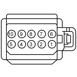 | Yes
INSTALL a new LH steering wheel switch. REFER to Section 211-05 . CLEAR the DTCs. REPEAT the self-test. No GO to AI3 . | ||||||||||||||||
| AI3 CHECK THE MESSAGE CENTER SWITCH SIGNAL AND RETURN CIRCUITS BETWEEN THE LH STEERING WHEEL SWITCH AND THE LOWER CLOCKSPRING FOR AN OPEN | |||||||||||||||||
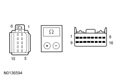 | Yes
GO to AI5 . No GO to AI4 . | ||||||||||||||||
| AI4 CHECK THE MESSAGE CENTER SWITCH SIGNAL AND RETURN CIRCUITS BETWEEN THE LH STEERING WHEEL SWITCH AND THE UPPER CLOCKSPRING FOR AN OPEN | |||||||||||||||||
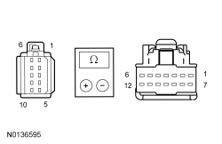 | Yes
INSTALL a new clockspring. REFER to Section 501-20B . CLEAR the DTC. REPEAT the self-test. No INSTALL a new steering wheel. REFER to Section 211-04 . CLEAR the DTC. REPEAT the self-test. | ||||||||||||||||
| AI5 CHECK THE MESSAGE CENTER SWITCH SIGNAL CIRCUIT BETWEEN THE LH STEERING WHEEL SWITCH AND THE LOWER CLOCKSPRING FOR A SHORT TO GROUND | |||||||||||||||||
| Yes
GO to AI7 . No GO to AI6 . | ||||||||||||||||
| AI6 CHECK THE MESSAGE CENTER SWITCH SIGNAL CIRCUIT BETWEEN THE LH STEERING WHEEL SWITCH AND THE UPPER CLOCKSPRING FOR A SHORT TO GROUND | |||||||||||||||||
| Yes
INSTALL a new clockspring. REFER to Section 501-20B . CLEAR the DTC. REPEAT the self-test. No INSTALL a new steering wheel. REFER to Section 211-04 . CLEAR the DTC. REPEAT the self-test. | ||||||||||||||||
| AI7 CHECK THE MESSAGE CENTER SWITCH SIGNAL AND RETURN CIRCUITS BETWEEN THE IPC AND THE LOWER CLOCKSPRING FOR AN OPEN | |||||||||||||||||
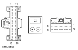 | Yes
GO to AI8 . No REPAIR the circuit. | ||||||||||||||||
| AI8 CHECK THE MESSAGE CENTER SWITCH SIGNAL CIRCUIT BETWEEN THE IPC AND THE LOWER CLOCKSPRING FOR A SHORT TO GROUND | |||||||||||||||||
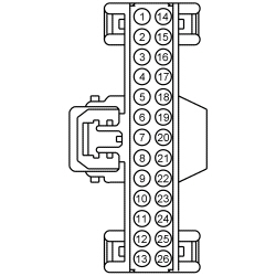 | Yes
GO to AI10 . No REPAIR the circuit. | ||||||||||||||||
| AI9 CHECK FOR VOLTAGE FROM THE IPC | |||||||||||||||||
| Yes
INSTALL a new LH steering wheel switch. REFER to Section 211-05 . TEST the system for normal operation. No GO to AI10 . | ||||||||||||||||
| AI10 CHECK FOR CORRECT IPC OPERATION | |||||||||||||||||
| Yes
INSTALL a new IPC . REFER to Instrument Panel Cluster (IPC) in this section. TEST the system for normal operation. No The system is operating correctly at this time. The concern may have been caused by a loose or corroded connector. | ||||||||||||||||
Pinpoint Test AJ: The Compass Is Inoperative
Diagnostics in this manual assume a certain skill level and knowledge of Ford-specific diagnostic practices. Refer to Diagnostic Methods in Section 100-00 for information regarding these diagnostic practices.
Refer to Wiring Diagrams Cell 124 , Power Mirrors for schematic and connector information.
The compass module (integral to the auto-dimming interior mirror) provides vehicle directional inputs to the Instrument Panel Cluster (IPC), which sends the compass information to the Front Display Interface Module (FDIM) over the Medium Speed Controller Area Network (MS-CAN). The FDIM displays the compass direction according to the information that has been provided by the compass module to the IPC .
This pinpoint test is intended to diagnose the following:
NOTICE: Use the correct probe adapter(s) when making measurements. Failure to use the correct probe adapter(s) may damage the connector.
| Test Step | Result / Action to Take | ||||||||||||||||||||||||
|---|---|---|---|---|---|---|---|---|---|---|---|---|---|---|---|---|---|---|---|---|---|---|---|---|---|
| AJ1 CHECK THE COMPASS DISPLAY | |||||||||||||||||||||||||
| Yes
If the compass display illuminates with only 2 bars, GO to AJ2 . If the compass display turns on, but it does not display all directions, or indicates CAL, GO to Pinpoint Test AK . No REFER to Section 415-00 . | ||||||||||||||||||||||||
| AJ2 CHECK THE COMPASS MODULE VOLTAGE SUPPLY AT THE INTERIOR AUTO-DIMMING MIRROR | |||||||||||||||||||||||||
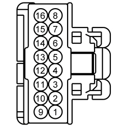 | Yes
GO to AJ3 . No VERIFY the Smart Junction Box (SJB) fuse 41 (15A) is OK. If OK, REPAIR the circuit. TEST the system for normal operation. If not OK, REFER to the Wiring Diagrams Manual to identify the possible causes of the circuit short. | ||||||||||||||||||||||||
| AJ3 CHECK THE INTERIOR AUTO-DIMMING MIRROR GROUND FOR CONTINUITY AT THE MIRROR | |||||||||||||||||||||||||
With Video Display
Without Video Display
| Yes
GO to AJ4 . No REPAIR the circuit. TEST the system for normal operation. | ||||||||||||||||||||||||
| AJ4 CHECK THE DTCs IN THE FDIM | |||||||||||||||||||||||||
| Yes
REFER to Section 415-00 . No GO to AJ5 . | ||||||||||||||||||||||||
| AJ5 CHECK THE COMPASS DATA + AND DATA - CIRCUITS FOR A SHORT TO VOLTAGE | |||||||||||||||||||||||||
| Yes
REPAIR the circuit in question. TEST the system for normal operation. No GO to AJ6 . | ||||||||||||||||||||||||
| AJ6 CHECK THE COMPASS DATA PLUS (+) CIRCUIT FOR AN OPEN | |||||||||||||||||||||||||
With Camera Mirror
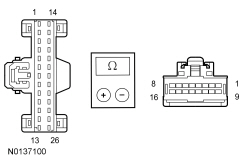 | Yes
GO to AJ7 . No REPAIR the circuit. CLEAR the DTCs. REPEAT the self-test. | ||||||||||||||||||||||||
| AJ7 CHECK THE COMPASS DATA PLUS (+) CIRCUIT FOR A SHORT TO GROUND | |||||||||||||||||||||||||
| Yes
GO to AJ8 . No REPAIR the circuit. CLEAR the DTCs. REPEAT the self-test. | ||||||||||||||||||||||||
| AJ8 CHECK THE COMPASS DATA MINUS (-) CIRCUIT FOR AN OPEN | |||||||||||||||||||||||||
| Yes
GO to AJ9 . No REPAIR the circuit. CLEAR the DTCs. REPEAT the self-test. | ||||||||||||||||||||||||
| AJ9 CHECK THE COMPASS DATA MINUS (-) CIRCUIT FOR A SHORT TO GROUND | |||||||||||||||||||||||||
| Yes
GO to AJ10 . No REPAIR the circuit. CLEAR the DTCs. REPEAT the self-test. | ||||||||||||||||||||||||
| AJ10 CHECK FOR DTC U0161:87 OR DTC U0161:92 | |||||||||||||||||||||||||
| Yes
INSTALL a new auto-dimming interior mirror. REFER to Section 501-09 . ADJUST the zone setting. REFER to Compass Zone Adjustment in this section. CALIBRATE the compass. REFER to Compass Calibration in this section. TEST the system for normal operation. No GO to AJ11 . | ||||||||||||||||||||||||
| AJ11 CHECK FOR CORRECT IPC OPERATION | |||||||||||||||||||||||||
| Yes
INSTALL a new IPC . REFER to Instrument Panel Cluster (IPC) in this section. CLEAR the DTCs. REPEAT the self-test. TEST the system for normal operation. No The system is operating correctly at this time. The concern may have been caused by a loose or corroded connector. CLEAR the DTCs. REPEAT the self-test. | ||||||||||||||||||||||||
Pinpoint Test AK: The Compass Is Inaccurate
Diagnostics in this manual assume a certain skill level and knowledge of Ford-specific diagnostic practices. Refer to Diagnostic Methods in Section 100-00 for information regarding these diagnostic practices.
NOTE: This procedure is only applicable to vehicles without navigation. If the compass display is inaccurate on a vehicle with navigation, install a new Front Display Interface Module (FDIM). Refer to Section 415-00 .
When calibrated correctly, the compass module (integral to the auto-dimming interior mirror) provides vehicle directional inputs to the Instrument Panel Cluster (IPC) which sends the compass information to the FDIM over the Medium Speed Controller Area Network (MS-CAN). The FDIM displays the vehicle heading based on the selected zone setting.
This pinpoint test is intended to diagnose the following:
NOTICE: Use the correct probe adapter(s) when making measurements. Failure to use the correct probe adapter(s) may damage the connector.
| Test Step | Result / Action to Take | ||||||||||||||||||
|---|---|---|---|---|---|---|---|---|---|---|---|---|---|---|---|---|---|---|---|
| AK1 CHECK THE AUTO-DIMMING INTERIOR MIRROR POSITION | |||||||||||||||||||
| Yes
GO to AK2 . No REPOSITION the auto-dimming interior mirror so the compass connector is located on the bottom of the mirror. REFER to Section 501-09 . TEST the system for normal operation. | ||||||||||||||||||
| AK2 CHECK THE COMPASS ACCURACY | |||||||||||||||||||
| Yes
The compass is OK. The concern may have been caused by an incorrect zone setting, or the compass was out of calibration. No INSTALL a new compass module. REFER to Auto-Dimming Interior Mirror in Section 501-09 . SET the zone. REFER to Compass Zone Adjustment in this section. CALIBRATE the compass. REFER to Compass Calibration in this section. TEST the system for normal operation. |
Pinpoint Test AL: The CHECK FUEL FILL INLET Message Is Inoperative/Always On
Diagnostics in this manual assume a certain skill level and knowledge of Ford-specific diagnostic practices. Refer to Diagnostic Methods in Section 100-00 for information regarding these diagnostic practices.
The PCM monitors the fuel tank evaporative emission system for significant leaks that occur following refueling of the vehicle. Once the PCM detects a fuel vapor leak, the PCM sends the Instrument Panel Cluster (IPC) a message over the High Speed Controller Area Network (HS-CAN) communication bus to turn on the CHECK FUEL FILL INLET message. DTC P0457 sets in the PCM following a successful cruise test, which is initiated when the vehicle is driven at a steady speed above 64 km/h (40 mph) for a duration of approximately 4-5 minutes. If the PCM is unable to successfully run the cruise test, the IPC does not receive the message from the PCM and the CHECK FUEL FILL INLET message remains off.
If the IPC does not receive the fuel cap off data from the PCM for 5 seconds or less, the IPC defaults the CHECK FUEL FILL INLET message to the last setting, based upon the last known good data message. If the IPC does not receive the fuel cap off data from the PCM for more than 5 seconds or if the data received is deemed invalid, the IPC sets DTC U0100:87 in continuous memory and defaults the CHECK FUEL FILL INLET message off.
NOTE: If DTC U0100:87 is set in the IPC , other observable symptoms can be an inoperative speedometer or odometer.
This pinpoint test is intended to diagnose the following:
| Test Step | Result / Action to Take |
|---|---|
| AL1 CHECK THE MESSAGE CENTER DISPLAY OPERATION | |
| Yes
GO to AL2 . No INSTALL a new IPC . REFER to Instrument Panel Cluster (IPC) in this section. TEST the system for normal operation. |
| AL2 RETRIEVE THE RECORDED PCM DTCs FROM THE KOEO SELF-TEST | |
| Yes
If the CHECK FUEL FILL INLET message is displayed, REFER to the Powertrain Control/Emissions Diagnosis (PC/ED) manual. If the CHECK FUEL FILL INLET message is not displayed, GO to AL3 . No If the CHECK FUEL FILL INLET message is always displayed, INSTALL a new IPC . REFER to Instrument Panel Cluster (IPC) in this section. TEST the system for normal operation. If the CHECK FUEL FILL INLET message is not displayed, the system is operating normally at this time. If the fuel cap was left off and the CHECK FUEL FILL INLET message did not turn on, driving conditions may not have allowed for the PCM to run the cruise test and message the IPC to turn on the check fuel cap warning indicator. |
| AL3 RETRIEVE THE RECORDED DTCs FROM THE IPC SELF-TEST | |
| Yes
GO to Pinpoint Test AS . No INSTALL a new PCM. REFER to Section 303-14 . |
Pinpoint Test AM: The Key-In-Ignition Warning Chime Is Inoperative
Diagnostics in this manual assume a certain skill level and knowledge of Ford-specific diagnostic practices. Refer to Diagnostic Methods in Section 100-00 for information regarding these diagnostic practices.
The Instrument Panel Cluster (IPC) receives the key-in-ignition warning status from the Smart Junction Box (SJB) over the Medium Speed Controller Area Network (MS-CAN) communication bus.
The SJB monitors the door ajar input from the LH front door and the key-in-ignition switch status. When the SJB detects a key-in-ignition voltage and the LH front door is open or ajar, the SJB sends the IPC a chime request message to sound the key-in-ignition warning chime.
This pinpoint test is intended to diagnose the following:
| Test Step | Result / Action to Take |
|---|---|
| AM1 CHECK THE SAFETY BELT WARNING CHIME OPERATION | |
| Yes
GO to AM2 . No INSTALL a new IPC . REFER to Instrument Panel Cluster (IPC) in this section. TEST the system for normal operation. |
| AM2 CHECK THE DOOR AJAR WARNING INDICATOR OPERATION | |
| Yes
GO to AM3 . No GO to Pinpoint Test T . |
| AM3 RETRIEVE THE RECORDED DTCs FROM THE SJB SELF-TEST | |
| Yes
GO to AM4 . No INSTALL a new SJB . REFER to Section 419-10 . TEST the system for normal operation. |
| AM4 CHECK THE IGNITION SWITCH | |
| Yes
REPAIR circuit CDC30 (BU/GY) for an open. CLEAR the DTCs. REPEAT the self-test. No INSTALL a new ignition switch. REFER to Section 211-05 . CLEAR the DTCs. REPEAT the self-test. |
Pinpoint Test AN: The Headlamps On Warning Chime Is Inoperative
Diagnostics in this manual assume a certain skill level and knowledge of Ford-specific diagnostic practices. Refer to Diagnostic Methods in Section 100-00 for information regarding these diagnostic practices.
The Smart Junction Box (SJB) receives the headlamp switch status from the headlamp switch. The SJB receives the LH front door ajar status from the LH front door ajar switch through hardwired circuitry.
The headlamps on warning chime sounds when the LH front door is opened with the ignition switch in the OFF position, no key-in-ignition input, and the headlamp switch is in the PARK or HEADLAMP ON position (or if a fault exists in the headlamp switch inputs). The SJB communicates the headlamp on chime request to the Instrument Panel Cluster (IPC) over the Medium Speed Controller Area Network (MS-CAN) communication bus. The autolamps feature must not be selected for the headlamps on warning chime to operate.
This pinpoint test is intended to diagnose the following:
| Test Step | Result / Action to Take |
|---|---|
| AN1 CHECK THE SAFETY BELT WARNING CHIME OPERATION | |
| Yes
GO to AN2 . No INSTALL a new IPC . REFER to Instrument Panel Cluster (IPC) in this section. TEST the system for normal operation. |
| AN2 CHECK THE SAFETY BELT WARNING CHIME OPERATION | |
| Yes
GO to AN3 . No INSTALL a new IPC . REFER to Instrument Panel Cluster (IPC) in this section. TEST the system for normal operation. |
| AN3 CHECK THE EXTERIOR LAMPS OPERATION | |
| Yes
GO to AN4 . No REFER to Section 417-01 . |
| AN4 CHECK THE DOOR AJAR WARNING INDICATOR OPERATION | |
| Yes
INSTALL a new SJB . REFER to Section 419-10 . TEST the system for normal operation. No GO to Pinpoint Test T . |
Pinpoint Test AO: The Chime Sounds When The Driver Door Is Ajar (No Key In Ignition And Headlamps Off)
Diagnostics in this manual assume a certain skill level and knowledge of Ford-specific diagnostic practices. Refer to Diagnostic Methods in Section 100-00 for information regarding these diagnostic practices.
Refer to Wiring Diagrams Cell 60 , Instrument Cluster for schematic and connector information.
The Instrument Panel Cluster (IPC) receives the key-in-ignition warning status from the Smart Junction Box (SJB) over the Medium Speed Controller Area Network (MS-CAN) communication bus.
The key-in-ignition warning switch (part of the ignition switch) is hardwired to the SJB . When the key is inserted into the ignition lock cylinder, the key-in-ignition switch closes and supplies voltage to the SJB .
The SJB monitors the door ajar input from the LH front door and the key-in-ignition switch status. When the SJB detects a key-in-ignition voltage and the LH front door is open or ajar, the SJB sends the IPC a chime request message to sound the key-in-ignition warning chime.
This pinpoint test is intended to diagnose the following:
NOTICE: Use the correct probe adapter(s) when making measurements. Failure to use the correct probe adapter(s) may damage the connector.
| Test Step | Result / Action to Take |
|---|---|
| AO1 CHECK THE IPC ILLUMINATION | |
| Yes
GO to AO2 . No REFER to Section 413-00 . |
| AO2 RETRIEVE THE RECORDED DTCs FROM THE SJB SELF-TEST | |
| Yes
GO to AO3 . No GO to AO4 . |
| AO3 CHECK THE SJB IGNITION INPUT PIDs | |
| Yes
INSTALL a new SJB . REFER to Section 419-10 . TEST the system for normal operation. No REFER to Section 211-05 to diagnose the ignition switch outputs to the SJB . |
| AO4 CHECK THE KEY-IN-IGNITION INPUT FOR VOLTAGE | |
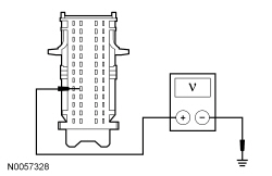 | Yes
GO to AO5 . No INSTALL a new SJB . REFER to Section 419-10 . TEST the system for normal operation. |
| AO5 CHECK THE KEY-IN-IGNITION INPUT CIRCUIT FOR A SHORT TO VOLTAGE | |
| Yes
REPAIR the circuit. TEST the system for normal operation. No INSTALL a new ignition switch. REFER to Section 211-05 . TEST the system for normal operation. |
Pinpoint Test AP: The Performance Shift Warning Chime Does Not Operate Correctly
Diagnostics in this manual assume a certain skill level and knowledge of Ford-specific diagnostic practices. Refer to Diagnostic Methods in Section 100-00 for information regarding these diagnostic practices.
The performance shift warning chime feature on/off status and the desired rpm for the chime to sound are items that are configured through the message center. The Instrument Panel Cluster (IPC) uses actual engine rpm sent to the IPC over the High Speed Controller Area Network (HS-CAN) communication bus and compares the value against the customer preset engine rpm to determine when to sound the chime. When actual engine rpm matches the preset engine rpm, the IPC sounds the chime.
This pinpoint test is intended to diagnose the following:
| Test Step | Result / Action to Take |
|---|---|
| AP1 CHECK THE KEY-IN-IGNITION WARNING CHIME OPERATION | |
| Yes
GO to AP2 . No INSTALL a new IPC . REFER to Instrument Panel Cluster (IPC) in this section. TEST the system for normal operation. |
| AP2 CHECK THE IPC CONFIGURATION | |
| Yes
INSTALL a new IPC . REFER to Instrument Panel Cluster (IPC) in this section. TEST the system for normal operation. No CONFIGURE the performance shift warning chime (tone) on and configure the desired rpm setting. REFER to Message Center Configuration in this section or the Owner's Literature for additional information. TEST the system for normal operation. |
Pinpoint Test AQ: The Safety Belt Warning Chime Does Not Operate Correctly/The Belt-Minder® Feature Does Not Operate Correctly
Diagnostics in this manual assume a certain skill level and knowledge of Ford-specific diagnostic practices. Refer to Diagnostic Methods in Section 100-00 for information regarding these diagnostic practices.
The Instrument Panel Cluster (IPC) receives the safety belt and Belt-Minder® requests from the Restraints Control Module (RCM) over the High Speed Controller Area Network (HS-CAN). The safety belt warning chime sounds for approximately 6 seconds when the driver safety belt is not fastened and the ignition is switched from the OFF or ACC to the RUN mode.
The Belt-Minder® feature supplements the safety belt warning function and is enabled after the safety belt warning is complete. The Belt-Minder® simultaneously sounds the chime and illuminates the safety belt warning lamp in the IPC once the vehicle speed has exceeded 5 km/h (3 mph), and remains active for 5 minutes from the time it is started.
There are 2 Belt-Minder® strategies used and implemented by the IPC as commanded by the RCM . The 2 strategies are designed to provide an increased chime tone activity. Belt-Minder® A provides 6 one-second sequences for the first minute of the Belt-Minder® warning. Belt-Minder® B provides 6 one-second sequences of 3 chime tones in rapid succession for the remainder of the Belt-Minder® warning.
NOTE: Make sure the Belt-Minder® chime operation is verified with the vehicle moving at least 5 km/h (3 mph).
The Belt-Minder® functions exactly the same for both administrator and MyKey® programmed keys except when a MyKey® programmed key is in use, the driver cannot configure the Belt-Minder® off. Once the Belt-Minder® is activated, the Belt-Minder® continues to chime periodically (without the 5 minute time out) with the audio system muted until the driver and passenger safety belts are fastened.
This pinpoint test is intended to diagnose the following:
| Test Step | Result / Action to Take |
|---|---|
| AQ1 CHECK THE KEY-IN-IGNITION WARNING CHIME OPERATION | |
| Yes
GO to AQ2 . No INSTALL a new IPC . REFER to Instrument Panel Cluster (IPC) in this section. TEST the system for normal operation. |
| AQ2 CHECK THE DRIVER AND FRONT PASSENGER SAFETY BELT BUCKLE SWITCHES | |
| Yes
GO to AQ3 . No REFER to Section 501-20B . |
| AQ3 CHECK THE SAFETY BELT WARNING INDICATOR FOR CORRECT OPERATION | |
| Yes
GO to AQ4 . No GO to Pinpoint Test S . |
| AQ4 CHECK THE SPEEDOMETER OPERATION | |
| Yes
GO to AQ5 . No GO to Pinpoint Test G . |
| AQ5 CHECK THE BELT-MINDER® CONFIGURATION | |
NOTE: Verify that an administrator key is used for this test and not a MyKey® programmed key. When a MyKey® programmed key is used, the Belt-Minder® is automatically turned on and cannot be disabled (if previously disabled by an administrator, the Belt-Minder® remains disabled when an administrator key is used). | Yes
INSTALL a new RCM . REFER to Section 501-20B . TEST the system for normal operation. No ACTIVATE the Belt-Minder® for the seating position in question. REFER to Belt-Minder® Deactivating/Activating in this section. TEST the system for normal operation. |
Pinpoint Test AR: The Turn Signal On Warning Chime Is Inoperative
Diagnostics in this manual assume a certain skill level and knowledge of Ford-specific diagnostic practices. Refer to Diagnostic Methods in Section 100-00 for information regarding these diagnostic practices.
The turn signal on warning chime sounds when the vehicle travels more than 3.2 km (2.0 miles) with the turn signal on. The Smart Junction Box (SJB) communicates the turn signal switch status to the Instrument Panel Cluster (IPC) over the Medium Speed Controller Area Network (MS-CAN). The IPC receives the odometer rolling count data from the PCM over the High Speed Controller Area Network (HS-CAN).
This pinpoint test is intended to diagnose the following:
| Test Step | Result / Action to Take |
|---|---|
| AR1 CHECK THE SAFETY BELT WARNING CHIME OPERATION | |
| Yes
GO to AR2 . No INSTALL a new IPC . REFER to Instrument Panel Cluster (IPC) in this section. TEST the system for normal operation. |
| AR2 CHECK THE KEY-IN-IGNITION WARNING CHIME OPERATION | |
| Yes
GO to AR3 . No GO to Pinpoint Test AM . |
| AR3 CHECK THE TURN SIGNAL INDICATORS OPERATION | |
| Yes
GO to AR4 . No GO to Pinpoint Test Z . |
| AR4 CHECK THE ODOMETER FOR CORRECT OPERATION | |
| Yes
INSTALL a new IPC . REFER to Instrument Panel Cluster (IPC) in this section. TEST the system for normal operation No GO to Pinpoint Test L . |
Pinpoint Test AS: DTC U0100:87
Diagnostics in this manual assume a certain skill level and knowledge of Ford-specific diagnostic practices. Refer to Diagnostic Methods in Section 100-00 for information regarding these diagnostic practices.
NOTE: Once the IPC sets DTC U0100:87, multiple gauges or indicators are likely to be inoperative in the IPC . Other modules that require data from the IPC all set communication DTCs and may also exhibit system function concerns.
This pinpoint test is intended to diagnose the following:
| Test Step | Result / Action to Take |
|---|---|
| AS1 VERIFY THAT THE SCAN TOOL CAN COMMUNICATE WITH THE PCM | |
| Yes
GO to AS2 . No REFER to Section 418-00 to diagnose no communication with the PCM. |
| AS2 CHECK THE IPC CONTINUOUS MEMORY DTCs | |
| Yes
GO to AS3 . No The system is operating correctly at this time. The DTC may have been set due to high network traffic or an intermittent fault condition. |
| AS3 RETRIEVE THE RECORDED DTCs FROM THE IPC SELF-TEST AND THE PCM KOEO SELF-TEST | |
| Yes
For IPC DTC U3003:16, GO to Pinpoint Test BB . For IPC DTC U3003:17, GO to Pinpoint Test BC . For the PCM, REFER to the Powertrain Control/Emissions Diagnosis (PC/ED) manual. No GO to AS4 . |
| AS4 CHECK FOR DTC U0100:87 SET IN OTHER MODULES | |
| Yes
INSTALL a new PCM. REFER to Section 303-14 . CLEAR the DTCs. REPEAT the self-test. No INSTALL a new IPC . REFER to Instrument Panel Cluster (IPC) in this section. TEST the system for normal operation. |
Pinpoint Test AT: DTC U021:00 And U0121:87
Diagnostics in this manual assume a certain skill level and knowledge of Ford-specific diagnostic practices. Refer to Diagnostic Methods in Section 100-00 for information regarding these diagnostic practices.
This pinpoint test is intended to diagnose the following:
| Test Step | Result / Action to Take |
|---|---|
| AT1 VERIFY THE CUSTOMER CONCERN | |
| Yes
GO to AT2 . No The system is operating normally at this time. The DTC may have been set due to high network traffic or an intermittent fault condition. |
| AT2 CHECK THE COMMUNICATION NETWORK | |
| Yes
GO to AT3 . No REFER to Section 418-00 . |
| AT3 RETRIEVE THE RECORDED DTCs FROM THE IPC AND ABS MODULE SELF-TESTS | |
| Yes
For IPC DTC U3003:16, GO to Pinpoint Test BB . For IPC DTC U3003:17, GO to Pinpoint Test BC . For the ABS module, REFER to Section 206-09 . No GO to AT4 . |
| AT4 RECHECK THE IPC DTCs | |
| Yes
INSTALL a new ABS module. REFER to Section 206-09 . CLEAR the DTCs. REPEAT the IPC self-test. If DTC U021:00 or U0121:87 is still present, INSTALL a new IPC . REFER to Instrument Panel Cluster (IPC) in this section. TEST the system for normal operation. No The system is operating correctly at this time. The DTC may have been set due to high network traffic or an intermittent fault condition. |
Pinpoint Test AU: DTC U0131:87
Diagnostics in this manual assume a certain skill level and knowledge of Ford-specific diagnostic practices. Refer to Diagnostic Methods in Section 100-00 for information regarding these diagnostic practices.
This pinpoint test is intended to diagnose the following:
| Test Step | Result / Action to Take |
|---|---|
| AU1 VERIFY THE CUSTOMER CONCERN | |
| Yes
GO to AU2 . No The system is operating normally at this time. The DTC may have been set due to high network traffic or an intermittent fault condition. |
| AU2 CHECK THE COMMUNICATION NETWORK | |
| Yes
GO to AU3 . No REFER to Section 418-00 . |
| AU3 RETRIEVE THE RECORDED DTCs FROM THE IPC AND PSCM SELF-TESTS | |
| Yes
For IPC DTC U3003:16, GO to Pinpoint Test BB . For IPC DTC U3003:17, GO to Pinpoint Test BC . For the PSCM , REFER to Section 211-00 . No GO to AU4 . |
| AU4 RECHECK THE IPC DTCs | |
NOTE: If new modules were installed prior to the DTC being set, the module configuration may be incorrectly set during the Programmable Module Installation (PMI) or the PMI may not have been carried out. | Yes
GO to AU5 . No The system is operating correctly at this time. The DTC may have been set due to high network traffic or an intermittent fault condition. |
| AU5 CHECK FOR DTC U0131:87 SET IN OTHER MODULES | |
| Yes
INSTALL a new steering gear. REFER to Section 211-02 . CLEAR the DTCs. REPEAT the IPC self-test. No INSTALL a new IPC . REFER to Instrument Panel Cluster (IPC) in this section. TEST the system for normal operation. |
Pinpoint Test AV: DTC U0140:87
Diagnostics in this manual assume a certain skill level and knowledge of Ford-specific diagnostic practices. Refer to Diagnostic Methods in Section 100-00 for information regarding these diagnostic practices.
This pinpoint test is intended to diagnose the following:
| Test Step | Result / Action to Take |
|---|---|
| AV1 VERIFY THE CUSTOMER CONCERN | |
| Yes
GO to AV2 . No The system is operating normally at this time. The DTC may have been set due to high network traffic or an intermittent fault condition. |
| AV2 CHECK THE COMMUNICATION NETWORK | |
| Yes
GO to AV3 . No REFER to Section 418-00 . |
| AV3 RETRIEVE THE RECORDED DTCs FROM THE IPC AND SJB SELF-TESTS | |
| Yes
For IPC DTC U3003:16, GO to Pinpoint Test BB . For IPC DTC U3003:17, GO to Pinpoint Test BC . For the SJB , REFER to Section 419-10 . No GO to AV4 . |
| AV4 RECHECK THE IPC DTCs | |
NOTE: If new modules were installed prior to the DTC being set, the module configuration may be incorrectly set during the Programmable Module Installation (PMI) or PMI may not have been carried out. | Yes
INSTALL a new SJB . REFER to Section 419-10 . CLEAR the DTCs. REPEAT the self-test. If DTC U0140:87 is still present, INSTALL a new IPC . REFER to Instrument Panel Cluster (IPC) in this section. TEST the system for normal operation. No The system is operating correctly at this time. The DTC may have been set due to high network traffic or an intermittent fault condition. |
Pinpoint Test AW: DTC U0142:87
Diagnostics in this manual assume a certain skill level and knowledge of Ford-specific diagnostic practices. Refer to Diagnostic Methods in Section 100-00 for information regarding these diagnostic practices.
This pinpoint test is intended to diagnose the following:
| Test Step | Result / Action to Take |
|---|---|
| AW1 VERIFY THE CUSTOMER CONCERN | |
| Yes
GO to AW2 . No The system is operating normally at this time. The DTC may have been set due to high network traffic or an intermittent fault condition. |
| AW2 CHECK THE COMMUNICATION NETWORK | |
| Yes
GO to AW3 . No REFER to Section 418-00 . |
| AW3 RETRIEVE THE RECORDED DTCs FROM THE IPC SELF-TEST | |
| Yes
For IPC DTC U3003:16, GO to Pinpoint Test BB . For IPC DTC U3003:17, GO to Pinpoint Test BC . No GO to AW4 . |
| AW4 RECHECK THE IPC DTCs | |
NOTE: If new modules were installed prior to the DTC being set, the module configuration may be incorrectly set during the Programmable Module Installation (PMI) or PMI may not have been carried out. | Yes
INSTALL a new BCM-B . REFER to Section 419-10 . CLEAR the DTCs. REPEAT the self-test. If DTC U0142:87 is still present, INSTALL a new IPC . REFER to Instrument Panel Cluster (IPC) in this section. TEST the system for normal operation. No The system is operating correctly at this time. The DTC may have been set due to high network traffic or an intermittent fault condition. |
Pinpoint Test AX: DTC U0151:87
Diagnostics in this manual assume a certain skill level and knowledge of Ford-specific diagnostic practices. Refer to Diagnostic Methods in Section 100-00 for information regarding these diagnostic practices.
This pinpoint test is intended to diagnose the following:
| Test Step | Result / Action to Take |
|---|---|
| AX1 VERIFY THE CUSTOMER CONCERN | |
| Yes
GO to AX2 . No The system is operating normally at this time. The DTC may have been set due to high network traffic or an intermittent fault condition. |
| AX2 CHECK THE COMMUNICATION NETWORK | |
| Yes
GO to AX3 . No REFER to Section 418-00 . |
| AX3 RETRIEVE THE RECORDED DTCs FROM THE IPC AND RCM SELF-TESTS | |
| Yes
For IPC DTC U3003:16, GO to Pinpoint Test BB . For IPC DTC U3003:17, GO to Pinpoint Test BC . For the RCM , REFER to Section 501-20B . No GO to AX4 . |
| AX4 RECHECK THE IPC DTCs | |
NOTE: If new modules were installed prior to the DTC being set, the module configuration may be incorrectly set during the Programmable Module Installation (PMI) or PMI may not have been carried out. | Yes
GO to AX5 . No The system is operating correctly at this time. The DTC may have been set due to high network traffic or an intermittent fault condition. |
| AX5 CHECK FOR DTC U0151:87 SET IN OTHER MODULES | |
| Yes
INSTALL a new RCM . REFER to Section 501-20B . CLEAR the DTCs. REPEAT the self-test. No INSTALL a new IPC . REFER to Instrument Panel Cluster (IPC) in this section. TEST the system for normal operation. |
Pinpoint Test AY: DTC U0159:00
Diagnostics in this manual assume a certain skill level and knowledge of Ford-specific diagnostic practices. Refer to Diagnostic Methods in Section 100-00 for information regarding these diagnostic practices.
This pinpoint test is intended to diagnose the following:
| Test Step | Result / Action to Take |
|---|---|
| AY1 VERIFY THE CUSTOMER CONCERN | |
| Yes
GO to AY2 . No The system is operating normally at this time. The DTC may have been set due to high network traffic or an intermittent fault condition. |
| AY2 CHECK THE COMMUNICATION NETWORK | |
| Yes
GO to AY3 . No REFER to Section 418-00 . |
| AY3 RETRIEVE THE RECORDED DTCs FROM THE IPC SELF-TEST | |
| Yes
For IPC DTC U3003:16, GO to Pinpoint Test BB . For IPC DTC U3003:17, GO to Pinpoint Test BC . No GO to AY4 . |
| AY4 RECHECK THE IPC DTCs | |
NOTE: If new modules were installed prior to the DTC being set, the module configuration may be incorrectly set during the Programmable Module Installation (PMI) or the PMI may not have been carried out. | Yes
INSTALL a new PAM . REFER to Section 413-13 . CLEAR the DTCs. REPEAT the IPC self-test. If DTC U0159:00 is still present, INSTALL a new IPC . REFER to Instrument Panel Cluster (IPC) in this section. TEST the system for normal operation. No The system is operating correctly at this time. The DTC may have been set due to high network traffic or an intermittent fault condition. |
Pinpoint Test AZ: DTC U0164:87
Diagnostics in this manual assume a certain skill level and knowledge of Ford-specific diagnostic practices. Refer to Diagnostic Methods in Section 100-00 for information regarding these diagnostic practices.
This pinpoint test is intended to diagnose the following:
| Test Step | Result / Action to Take |
|---|---|
| AZ1 VERIFY THE CUSTOMER CONCERN | |
| Yes
GO to AZ2 . No The system is operating normally at this time. The DTC may have been set due to high network traffic or an intermittent fault condition. |
| AZ2 CHECK THE COMMUNICATION NETWORK | |
| Yes
GO to AZ3 . No REFER to Section 418-00 . |
| AZ3 RETRIEVE THE RECORDED DTCs FROM THE IPC AND HVAC MODULE SELF-TESTS | |
| Yes
For IPC DTC U3003:16, GO to Pinpoint Test BB . For IPC DTC U3003:17, GO to Pinpoint Test BC . For the HVAC module, REFER to Section 412-00 . No GO to AZ4 . |
| AZ4 RECHECK THE IPC DTCs | |
NOTE: If new modules were installed prior to the DTC being set, the module configuration may be incorrectly set during the Programmable Module Installation (PMI) or PMI may not have been carried out. | Yes
INSTALL a new HVAC module. REFER to Section 412-01 . CLEAR the DTCs. REPEAT the IPC self-test. If DTC U0164:87 is still present, INSTALL a new IPC . REFER to Instrument Panel Cluster (IPC) in this section. TEST the system for normal operation. No The system is operating correctly at this time. The DTC may have been set due to high network traffic or an intermittent fault condition. |
Pinpoint Test BA: DTC U0184:87
Diagnostics in this manual assume a certain skill level and knowledge of Ford-specific diagnostic practices. Refer to Diagnostic Methods in Section 100-00 for information regarding these diagnostic practices.
This pinpoint test is intended to diagnose the following:
| Test Step | Result / Action to Take |
|---|---|
| BA1 VERIFY THE CUSTOMER CONCERN | |
| Yes
GO to BA2 . No The system is operating normally at this time. The DTC may have been set due to high network traffic or an intermittent fault condition. |
| BA2 CHECK THE COMMUNICATION NETWORK | |
| Yes
GO to BA3 . No REFER to Section 418-00 . |
| BA3 RETRIEVE THE RECORDED DTCs FROM THE IPC AND ACM SELF-TESTS | |
| Yes
For IPC DTC U3003:16, GO to Pinpoint Test BB . For IPC DTC U3003:17, GO to Pinpoint Test BC . For the ACM , REFER to Section 415-00 . No GO to BA4 . |
| BA4 RECHECK THE IPC DTCs | |
NOTE: If new modules were installed prior to the DTC being set, the module configuration may be incorrectly set during the Programmable Module Installation (PMI) or PMI may not have been carried out. | Yes
INSTALL a new ACM . REFER to Section 415-00 . CLEAR the DTCs. REPEAT the IPC self-test. If DTC U0184:87 is still present, INSTALL a new IPC . REFER to Instrument Panel Cluster (IPC) in this section. TEST the system for normal operation. No The system is operating correctly at this time. The DTC may have been set due to high network traffic or an intermittent fault condition. |
Pinpoint Test BB: DTC U3003:16
Diagnostics in this manual assume a certain skill level and knowledge of Ford-specific diagnostic practices. Refer to Diagnostic Methods in Section 100-00 for information regarding these diagnostic practices.
Refer to Wiring Diagrams Cell 60 , Instrument Cluster for schematic and connector information.
This pinpoint test is intended to diagnose the following:
NOTICE: Use the correct probe adapter(s) when making measurements. Failure to use the correct probe adapter(s) may damage the connector.
NOTE: Failure to disconnect the battery when instructed results in false resistance readings. Refer to Section 414-01 .
| Test Step | Result / Action to Take |
|---|---|
| BB1 RECHECK THE IPC DTCs | |
| Yes
GO to BB2 . No The system is operating correctly at this time. The DTC may have been set due to a previous low battery voltage condition. |
| BB2 CHECK FOR CHARGING SYSTEM DTCs IN THE PCM | |
| Yes
REFER to Section 414-00 . No GO to BB3 . |
| BB3 CHECK THE BATTERY CONDITION AND STATE OF CHARGE | |
| Yes
GO to BB4 . No REFER to Section 414-01 . |
| BB4 CHECK THE IPC VOLTAGE INPUT | |
| Yes
GO to BB6 . No GO to BB5 |
| BB5 CHECK THE IPC VOLTAGE SUPPLY | |
| Yes
GO to BB6 . No REPAIR the circuit for high resistance. CLEAR the DTC. REPEAT the self-test. |
| BB6 CHECK THE IPC GROUND CIRCUIT | |
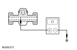 | Yes
GO to BB7 . No REPAIR the circuit for high resistance. CLEAR the DTCs. REPEAT the self-test. |
| BB7 CHECK FOR CORRECT IPC OPERATION | |
| Yes
INSTALL a new IPC . REFER to Instrument Panel Cluster (IPC) . TEST the system for normal operation. No The system is operating correctly at this time. The concern may have been caused by a loose or corroded connector. |
Pinpoint Test BC: DTC U3003:17
Diagnostics in this manual assume a certain skill level and knowledge of Ford-specific diagnostic practices. Refer to Diagnostic Methods in Section 100-00 for information regarding these diagnostic practices.
Refer to Wiring Diagrams Cell 60 , Instrument Cluster for schematic and connector information.
This pinpoint test is intended to diagnose the following:
NOTICE: Use the correct probe adapter(s) when making measurements. Failure to use the correct probe adapter(s) may damage the connector.
NOTE: DTC U3003:17 may be stored in the module memory due to past battery charging or vehicle jump starting events.
| Test Step | Result / Action to Take |
|---|---|
| BC1 CHECK FOR DTC B1317, B1676, P0563 (PCM) OR U3003:17 SET IN OTHER MODULES | |
| Yes
REFER to Section 414-00 to diagnose an overcharging condition. No GO to BC2 . |
| BC2 CHECK THE BATTERY VOLTAGE | |
| Yes
REFER to Section 414-00 to diagnose an overcharging condition. No GO to BC3 . |
| BC3 RECHECK FOR DTC U3003:17 | |
| Yes
INSTALL a new IPC . REFER to Instrument Panel Cluster (IPC) in this section. TEST the system for normal operation. No The system is operating normally at this time. The DTC may have been set previously during battery charging or while jump starting the vehicle. |
Pinpoint Test BD: DTC U300A:94
Diagnostics in this manual assume a certain skill level and knowledge of Ford-specific diagnostic practices. Refer to Diagnostic Methods in Section 100-00 for information regarding these diagnostic practices.
Refer to Wiring Diagrams Cell 60 , Instrument Cluster for schematic and connector information.
With the ignition switch in the START or RUN position, the Instrument Panel Cluster (IPC) receives voltage from the Smart Junction Box (SJB). With the ignition switch in the OFF position, the IPC receives its keep-alive voltage from the SJB . The IPC also receives a networked ignition status from the SJB over the Medium Speed Controller Area Network (MS-CAN) communication bus.
This pinpoint test is intended to diagnose the following:
NOTICE: Use the correct probe adapter(s) when making measurements. Failure to use the correct probe adapter(s) may damage the connector.
| Test Step | Result / Action to Take |
|---|---|
| BD1 CHECK THE IPC RUN/START VOLTAGE SUPPLY | |
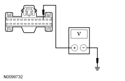 | Yes
GO to BD2 . No VERIFY the SJB fuse 36 (5A) is OK. If OK, REPAIR the circuit for an open. TEST the system for normal operation. If not OK, REFER to the Wiring Diagrams manual to identify the possible causes of the circuit short. |
| BD2 CHECK THE SJB INPUT PIDs FROM THE IGNITION SWITCH | |
| Yes
GO to BD3 . No REFER to Section 211-05 to diagnose the ignition outputs to the SJB . |
| BD3 CHECK THE IPC DTCs | |
| Yes
INSTALL a new SJB . REFER to Section 419-10 . TEST the system for normal operation. No The system is operating correctly at this time. The DTC may have been set due to high network traffic or an intermittent fault condition. |
Pinpoint Test BE: DTC U0122:87
Diagnostics in this manual assume a certain skill level and knowledge of Ford-specific diagnostic practices. Refer to Diagnostic Methods in Section 100-00 for information regarding these diagnostic practices.
This pinpoint test is intended to diagnose the following:
| Test Step | Result / Action to Take |
|---|---|
| BE1 VERIFY THE CUSTOMER CONCERN | |
| Yes
GO to BE2 . No The system is operating normally at this time. The DTC may have been set due to high network traffic or an intermittent fault condition. |
| BE2 CHECK THE COMMUNICATION NETWORK | |
| Yes
GO to BE3 . No REFER to Section 418-00 . |
| BE3 RETRIEVE THE RECORDED DTCs FROM THE IPC SELF-TEST | |
| Yes
For IPC DTC U3003:16, GO to Pinpoint Test BB . For IPC DTC U3003:17, GO to Pinpoint Test BC . No GO to BE4 . |
| BE4 RETRIEVE THE RECORDED DTCs FROM THE VDM SELF-TEST | |
| Yes
REFER to Section 204-05 . No GO to BE5 . |
| BE5 RECHECK THE IPC DTCs | |
NOTE: If new modules were installed prior to the DTC being set, the module configuration may be incorrectly set during the Programmable Module Installation (PMI) or the PMI may not have been carried out. | Yes
INSTALL a new VDM . REFER to Section 204-05 . CLEAR the DTCs. REPEAT the self-test. If DTC U0122:87 is still present, INSTALL a new IPC . REFER to Instrument Panel Cluster (IPC) in this section. TEST the system for normal operation. No The system is operating correctly at this time. The DTC may have been set due to high network traffic or an intermittent fault condition. |