
FLU77-4 or equivalent


105-R025D or equivalent
SECTION 417-01: Exterior Lighting
| 2014 Mustang Workshop Manual
|
DIAGNOSIS AND TESTING
| Procedure revision date: 01/07/2013
|
| Fluke 77-IV Digital Multimeter
FLU77-4 or equivalent |
| Vehicle Communication Module (VCM) and Integrated Diagnostic System (IDS) software with appropriate hardware, or equivalent scan tool
|
| Flex Probe Kit
105-R025D or equivalent |
Principles of Operation
The PCM monitors the transmission gear status. When the PCM detects the transmission is in REVERSE (R), the PCM sends a message to the Body Control Module B (BCM-B). When the BCM-B receives this message, it provides voltage to the reversing lamps.
Inspection and Verification
Visual Inspection Chart
| Electrical |
|---|
|
NOTE: Make sure to use the latest scan tool software release.
If the cause is not visually evident, connect the scan tool to the Data Link Connector (DLC).NOTE: The Vehicle Communication Module (VCM) LED prove-out confirms power and ground from the DLC are provided to the VCM .
If the scan tool does not communicate with the VCM :Symptom Chart
| Condition | Possible Sources | Action |
|---|---|---|
|
|
|
|
|
|
|
|
Pinpoint Tests
Pinpoint Test W: All The Reversing Lamps Are Inoperative
Refer to Wiring Diagrams Cell 11 , Fuse and Relay Information for schematic and connector information.
Refer to Wiring Diagrams Cell 93 , Reversing Lamps for schematic and connector information.
When the Body Control Module B (BCM-B) receives a message from the PCM indicating the transmission is in reverse, the BCM-B supplies voltage to the reversing lamps.
The PCM monitors the gear status from the transmission. When the transmission is in REVERSE (R), a message is sent to the BCM-B . If any gear status concerns exist, the PCM sets a DTC and the wrench indicator turns on.
The PCM sends a voltage signal to the reversing lamps switch. When the transmission is in REVERSE (R), the voltage signal is routed back to the PCM and the PCM sends a message to the BCM-B indicating the transmission is in reverse.
This pinpoint test is intended to diagnose the following:
NOTICE: Use the correct probe adapter(s) when making measurements. Failure to use the correct probe adapter(s) may damage the connector.
| Test Step | Result / Action to Take |
|---|---|
| W1 CARRY OUT THE BCM-B REVERSING LAMP CONTROL ACTIVE COMMAND USING THE SCAN TOOL | |
| Yes
GO to W7 . No GO to W2 . |
| W2 CHECK FOR THE BCM-B REVERSE LAMP SHORT TO GROUND DTC | |
| Yes
GO to W4 . No GO to W3 . |
| W3 CHECK THE STOPLAMP OPERATION | |
| Yes
GO to W11 . No REFER to Stoplamps in this section. |
| W4 ISOLATE THE LH REAR LAMP SHORT TO GROUND | |
| Yes
GO to W5 . No REPAIR or INSTALL a new LH rear lamp jumper harness. TEST the system for normal operation. |
| W5 ISOLATE THE RH REAR LAMP SHORT TO GROUND | |
| Yes
GO to W6 . No REPAIR or INSTALL a new RH rear lamp jumper harness. TEST the system for normal operation. |
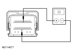
| W6 CHECK THE BCM-B REVERSE LAMP OUTPUT CIRCUITS FOR A SHORT TO GROUND | |
 | Yes
GO to W11 . No REPAIR the circuit in question for a short to ground. After the repair: If no DTCs are present, TEST the system for normal operation. If DTC U1000:00 is present, CLEAR the DTCs and REPEAT the self-test (required to enable the stoplamp output driver) . TEST the system for normal operation. If DTC U3000:49 is present, INSTALL a new SJB . REFER to Section 419-10 . TEST the system for normal operation. |
| W7 CHECK FOR PCM DTCs | |
| Yes
REFER to Section 419-10 or the Powertrain Control/Emissions Diagnosis (PC/ED) manual as necessary. No For vehicles with an automatic transmission, REFER to Section 307-01 to diagnose a Transmission Range (TR) input concern. For vehicles with a manual transmission, GO to W8 . |
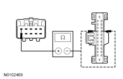
| W8 BYPASS THE REVERSING LAMP SWITCH | |
  | Yes
REMOVE the jumper wire. INSTALL a new reversing lamp switch. REFER to Reversing Lamp Switch in this section. TEST the system for normal operation. No REMOVE the jumper wire. GO to W9 . |
| W9 CHECK THE REVERSING LAMP SWITCH INPUT | |
  | Yes
GO to W12 . No GO to W10 . |
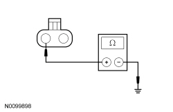
| W10 CHECK THE REVERSING LAMP SWITCH CIRCUITS FOR AN OPEN | |
   | Yes
REPAIR circuit RE406 (GY/VT) for an open. TEST the system for normal operation. No REPAIR circuit CET47 (BU) for an open. TEST the system for normal operation. |
| W11 CHECK FOR CORRECT BCM-B OPERATION | |
| Yes
INSTALL a new BCM-B . REFER to Section 419-10 . TEST the system for normal operation. No The system is operating correctly at this time. The concern may have been caused by a loose or corroded connector. CLEAR the DTCs. REPEAT the self-test. |
| W12 CHECK FOR CORRECT PCM OPERATION | |
| Yes
INSTALL a new PCM. REFER to Section 303-14 . TEST the system for normal operation. No The system is operating correctly at this time. The concern may have been caused by a loose or corroded connector. |
Pinpoint Test X: An Individual Reversing Lamp Is Inoperative
Refer to Wiring Diagrams Cell 93 , Reversing Lamps for schematic and connector information.
When the Body Control Module B (BCM-B) receives a message from the PCM indicating the transmission is in reverse, the BCM-B supplies voltage to the reversing lamps.
This pinpoint test is intended to diagnose the following:
NOTICE: Use the correct probe adapter(s) when making measurements. Failure to use the correct probe adapter(s) may damage the connector.
| Test Step | Result / Action to Take |
|---|---|
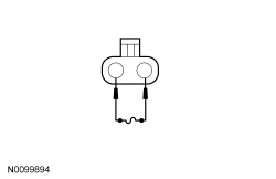
| X1 CHECK FOR VOLTAGE TO THE REVERSING LAMP | |
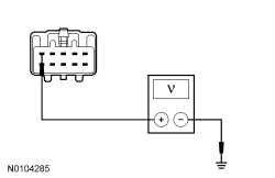 | Yes
REPAIR or INSTALL a new rear lamp jumper harness. TEST the system for normal operation. No GO to X2 . |
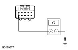
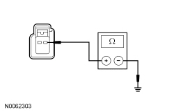
| X2 CHECK THE REVERSING LAMP VOLTAGE SUPPLY CIRCUIT FOR AN OPEN | |
 | Yes
GO to X3 . No REPAIR circuit CLS10 (GN/BN) or CLS11 (GY/VT) for an open. TEST the system for normal operation. |
| X3 CHECK FOR CORRECT BCM-B OPERATION | |
| Yes
INSTALL a new BCM-B . REFER to Section 419-10 . TEST the system for normal operation. No The system is operating correctly at this time. The concern may have been caused by a loose or corroded connector. CLEAR the DTCs. REPEAT the self-test. |
Pinpoint Test Y: The Reversing Lamps Are On Continuously
Refer to Wiring Diagrams Cell 93 , Reversing Lamps for schematic and connector information.
When the Body Control Module B (BCM-B) receives a message from the PCM indicating the transmission is in reverse, the BCM-B supplies voltage to the reversing lamps.
The PCM monitors the gear status from the transmission. When the transmission is in REVERSE (R), a message is sent to the BCM-B . If any gear status concerns exist, the PCM sets a DTC and the wrench indicator turns on.
The PCM sends a voltage signal to the reversing lamps switch. When the transmission is in REVERSE (R), the voltage signal is routed back to the PCM and the PCM sends a message to the BCM-B indicating the transmission is in reverse.
This pinpoint test is intended to diagnose the following:
NOTICE: Use the correct probe adapter(s) when making measurements. Failure to use the correct probe adapter(s) may damage the connector.
| Test Step | Result / Action to Take |
|---|---|
| Y1 CHECK FOR BCM-B DTC B1272:15 | |
| Yes
GO to Y2 . No GO to Y3 . |
| Y2 CHECK THE BCM-B REVERSING LAMP OUTPUT CIRCUITS FOR A SHORT TO VOLTAGE | |
| Yes
REPAIR circuit CLS10 (GN/BN) (LH reverse lamp) or circuit CLS11 (GY/VT) (RH reverse lamp) for a short to voltage. CLEAR the DTCs. REPEAT the self-test. No GO to Y6 . |
| Y3 CHECK FOR PCM DTCs | |
| Yes
REFER to Section 419-10 or the Powertrain Control/Emissions Diagnosis (PC/ED) manual as necessary. No For vehicles with an automatic transmission, REFER to Section 307-01 to diagnose a Transmission Range (TR) input concern. For vehicles with a manual transmission, GO to Y4 . |
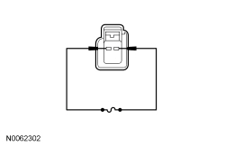
| Y4 CHECK THE REVERSING LAMP SWITCH | |
| Yes
GO to Y5 . No INSTALL a new reversing lamp switch. REFER to Reversing Lamp Switch in this section. TEST the system for normal operation. |
| Y5 CHECK THE REVERSING LAMP SWITCH INPUT CIRCUIT FOR A SHORT TO GROUND | |
  | Yes
GO to Y7 . No REPAIR circuit CET47 (BU) for a short to ground. TEST the system for normal operation. |
| Y6 CHECK FOR CORRECT BCM-B OPERATION | |
| Yes
INSTALL a new BCM-B . REFER to Section 419-10 . TEST the system for normal operation. No The system is operating correctly at this time. The concern may have been caused by a loose or corroded connector. CLEAR the DTCs. REPEAT the self-test. |
| Y7 CHECK FOR CORRECT PCM OPERATION | |
| Yes
INSTALL a new PCM. REFER to Section 303-14 . TEST the system for normal operation. No The system is operating correctly at this time. The concern may have been caused by a loose or corroded connector. |