
FLU77-4 or equivalent


300-NUD105-R025DE or equivalent
SECTION 419-10: Multifunction Electronic Modules
| 2014 Mustang Workshop Manual
|
DIAGNOSIS AND TESTING
| Procedure revision date: 01/07/2013
|
| Fluke 77-IV Digital Multimeter
FLU77-4 or equivalent |
| Vehicle Communication Module (VCM) and Integrated Diagnostic System (IDS) software with appropriate hardware, or equivalent scan tool
|
| Flex Probe Kit
300-NUD105-R025DE or equivalent |
Principles of Operation
The Body Control Module B (BCM-B) controls various systems by monitoring inputs from switches, sensors and messages sent from other modules on the Medium Speed Controller Area Network (MS-CAN). Based on the inputs received, the BCM-B activates outputs. For example, the BCM-B monitors the stoplamp switch and messages received from the Smart Junction Box (SJB) regarding ignition state and door ajar status. Based on this input, the BCM-B may provide voltage to the stoplamps or activate the ambient lighting.
Field-Effect Transistor (FET) Protection
A Field-Effect Transistor (FET) is a type of transistor that when used with module software can be used to monitor and control current flow on module outputs. The FET protection strategy is used to prevent module damage in the event of excessive current flow.
The BCM-B utilizes an FET protective circuit strategy for many of its outputs (for example, a stoplamp output circuit). Output loads (current level) are monitored for excessive current (typically short circuits) and are shut down (turns off the voltage or ground provided by the module) when a fault event is detected. A short circuit DTC is stored at the fault event and a cumulative counter is started.
When the demand for the output is no longer present, the module resets the FET circuit protection to allow the circuit to function. The next time the driver requests a circuit to activate that has been shut down by a previous short ( FET protection) and the circuit is still shorted, the FET protection shuts off the circuit again and the cumulative counter advances.
When the excessive circuit load occurs often enough, the module shuts down the output until a repair procedure is carried out. Each FET protected circuit has 3 predefined levels of short circuit tolerance based on the harmful effect of each circuit fault on the FET and the ability of the FET to withstand it. A module lifetime level of fault events is established based upon the durability of the FET . If the total tolerance level is determined to be 600 fault events, the 3 predefined levels would be 200, 400 and 600 fault events.
When each tolerance level is reached, the short circuit DTC that was stored on the first failure cannot be cleared by a command to clear the continuous DTCs. The module does not allow this code to be cleared or the circuit restored to normal operation until a successful self-test proves that the fault has been repaired. After the self-test has successfully completed (no on-demand DTCs present), DTC U1000:00 and the associated DTC (the DTC related to the shorted circuit) automatically clears and the circuit function returns.
When each level is reached, the DTC associated with the short circuit sets along with DTC U1000:00. These DTCs can be cleared using the module on-demand self-test, then the Clear DTC operation on the scan tool (if the on-demand test shows the fault corrected). The module never resets the fault event counter to zero and continues to advance the fault event counter as short circuit fault events occur.
If the number of short circuit fault events reach the third level, then DTCs U1000:00 and U3000:49 set along with the associated short circuit DTC. DTC U3000:49 cannot be cleared and the module must be replaced after the repair.
Inspection and Verification
Visual Inspection Chart
| Electrical |
|---|
|
NOTE: Make sure to use the latest scan tool software release.
If the cause is not visually evident, connect the scan tool to the Data Link Connector (DLC).NOTE: The Vehicle Communication Module (VCM) LED prove-out confirms power and ground from the DLC are provided to the VCM .
If the scan tool does not communicate with the VCM :DTC Charts
Body Control Module B (BCM-B) DTC Chart
NOTE: This module utilizes a 5-character DTC followed by a 2-character failure-type code. The failure-type code provides information about specific fault conditions such as opens, or shorts to ground. Continuous memory DTCs have an additional 2-character DTC status code suffix to assist in determining DTC history.
| DTC | Description | Action |
|---|---|---|
| B109F:08 | Intrusion Sensor Module: Bus Signal/Message Failures | REFER to Section 419-01A . |
| B109F:49 | Intrusion Sensor Module: Internal Electronic Failure | REFER to Section 419-01A . |
| B109F:55 | Intrusion Sensor Module: Not Configured | CARRY OUT Programmable Module Installation (PMI) on the BCM-B . REFER to Section 418-01 . |
| B109F:97 | Intrusion Sensor Module: Component Or System Operation Obstructed Or Blocked | REFER to Section 419-01A . |
| B1219:11 | Interior Boot/Trunk Release Switch: Circuit Short To Ground | REFER to Section 501-14 . |
| B1265:23 | Left Rear Turn Lamp Feedback: Signal Stuck Low | REFER to Section 417-01 . |
| B1265:24 | Left Rear Turn Lamp Feedback: Signal Stuck High | REFER to Section 417-01 . |
| B1266:23 | Right Rear Turn Lamp Feedback: Signal Stuck Low | REFER to Section 417-01 . |
| B1266:24 | Right Rear Turn Lamp Feedback: Signal Stuck High | REFER to Section 417-01 . |
| B1267:11 | Convertible/Folding Top Activation Up Switch: Circuit Short To Ground | REFER to Section 501-18 . |
| B1268:11 | Convertible/Folding Top Activation Down Switch: Circuit Short To Ground | REFER to Section 501-18 . |
| B1269:11 | Convertible/Folding Top Fully Up Position Switch: Circuit Short To Ground | REFER to Section 501-11 . |
| B126D:15 | Convertible/Folding Top Fully Down Position Switch: Circuit Short To Battery Or Open | REFER to Section 501-11 . |
| B126E:23 | Right Rear Window Fully Down Feedback: Signal Stuck Low | REFER to Section 501-18 . |
| B126E:24 | Right Rear Window Fully Down Feedback: Signal Stuck High | REFER to Section 501-18 . |
| B126F:23 | Left Rear Window Fully Down Feedback: Signal Stuck Low | REFER to Section 501-18 . |
| B126F:24 | Left Rear Window Fully Down Feedback: Signal Stuck High | REFER to Section 501-18 . |
| B1270:11 | High Mounted Stop Lamp: Circuit Short To Ground | REFER to Section 417-01 . |
| B1270:15 | High Mounted Stop Lamp: Circuit Short To Battery Or Open | REFER to Section 417-01 . |
| B1271:11 | Left Stop/Turn Inner Lamp: Circuit Short To Ground | REFER to Section 417-01 . |
| B1271:15 | Left Stop/Turn Inner Lamp: Circuit Short To Battery Or Open | REFER to Section 417-01 . |
| B1272:11 | Right Stop/Turn Inner Lamp: Circuit Short To Ground | REFER to Section 417-01 . |
| B1272:15 | Right Stop/Turn Inner Lamp: Circuit Short To Battery Or Open | REFER to Section 417-01 . |
| B1273:11 | Right Stop/Turn Middle Lamp: Circuit Short To Ground | REFER to Section 417-01 . |
| B1273:15 | Right Stop/Turn Middle Lamp: Circuit Short To Battery Or Open | REFER to Section 417-01 . |
| B1274:11 | Left Stop/Turn Middle Lamp: Circuit Short To Ground | REFER to Section 417-01 . |
| B1274:15 | Left Stop/Turn Middle Lamp: Circuit Short To Battery Or Open | REFER to Section 417-01 . |
| B1275:11 | Left Stop/Turn Outer Lamp: Circuit Short To Ground | REFER to Section 417-01 . |
| B1275:15 | Left Stop/Turn Outer Lamp: Circuit Short To Battery Or Open | REFER to Section 417-01 . |
| B1276:11 | Right Stop/Turn Outer Lamp: Circuit Short To Ground | REFER to Section 417-01 . |
| B1276:15 | Right Stop/Turn Outer Lamp: Circuit Short To Battery Or Open | REFER to Section 417-01 . |
| B1277:11 | Reverse Lamp: Circuit Short To Ground | REFER to Section 417-01 . |
| B1277:15 | Reverse Lamp: Circuit Short To Battery Or Open | REFER to Section 417-01 . |
| B1278:12 | Convertible/Foldable Top Up Relay: Circuit Short To Battery | REFER to Section 501-18 . |
| B1278:14 | Convertible/Foldable Top Up Relay: Circuit Short To Ground Or Open | REFER to Section 501-18 . |
| B1279:12 | Convertible/Foldable Top Down Relay: Circuit Short To Battery | REFER to Section 501-18 . |
| B1279:14 | Convertible/Foldable Top Down Relay: Circuit Short To Ground Or Open | REFER to Section 501-18 . |
| B127A:12 | Global Window Control: Circuit Short To Battery | REFER to Section 501-11 . |
| B127A:14 | Global Window Control: Circuit Short To Ground Or Open | REFER to Section 501-11 . |
| B127B:11 | Ambient Lighting Zone 1 Output Red LED: Circuit Short To Ground | REFER to Section 417-02 . |
| B127B:15 | Ambient Lighting Zone 1 Output Red LED: Circuit Short To Battery Or Open | REFER to Section 417-02 . |
| B127C:11 | Ambient Lighting Zone 2 Output Red LED: Circuit Short To Ground | REFER to Section 417-02 . |
| B127C:15 | Ambient Lighting Zone 2 Output Red LED: Circuit Short To Battery Or Open | REFER to Section 417-02 . |
| B127D:11 | Ambient Lighting Zone 3 Output Red LED: Circuit Short To Ground | REFER to Section 417-02 . |
| B127D:15 | Ambient Lighting Zone 3 Output Red LED: Circuit Short To Battery Or Open | REFER to Section 417-02 . |
| B127E:11 | Ambient Lighting Zone 1 Output Green LED: Circuit Short To Ground | REFER to Section 417-02 . |
| B127E:15 | Ambient Lighting Zone 1 Output Green LED: Circuit Short To Battery Or Open | REFER to Section 417-02 . |
| B127F:11 | Ambient Lighting Zone 2 Output Green LED: Circuit Short To Ground | REFER to Section 417-02 . |
| B127F:15 | Ambient Lighting Zone 2 Output Green LED: Circuit Short To Battery Or Open | REFER to Section 417-02 . |
| B1280:11 | Ambient Lighting Zone 3 Output Green LED: Circuit Short To Ground | REFER to Section 417-02 . |
| B1280:15 | Ambient Lighting Zone 3 Output Green LED: Circuit Short To Battery Or Open | REFER to Section 417-02 . |
| B1281:11 | Ambient Lighting Zone 1 Output Blue LED: Circuit Short To Ground | REFER to Section 417-02 . |
| B1281:15 | Ambient Lighting Zone 1 Output Blue LED: Circuit Short To Battery Or Open | REFER to Section 417-02 . |
| B1282:11 | Ambient Lighting Zone 2 Output Blue LED: Circuit Short To Ground | REFER to Section 417-02 . |
| B1282:15 | Ambient Lighting Zone 2 Output Blue LED: Circuit Short To Battery Or Open | REFER to Section 417-02 . |
| B1283:11 | Ambient Lighting Zone 3 Output Blue LED: Circuit Short To Ground | REFER to Section 417-02 . |
| B1283:15 | Ambient Lighting Zone 3 Output Blue LED: Circuit Short To Battery Or Open | REFER to Section 417-02 . |
| B1284:12 | Trunk/Boot Open Activation Request Hardwire: Circuit Short To Battery | REFER to Section 501-14 . |
| B1284:14 | Trunk/Boot Open Activation Request Hardwire: Circuit Short To Ground Or Open | REFER to Section 501-14 . |
| P0801:11 | Reverse Inhibit Control Circuit: Circuit Short To Ground | REFER to Section 501-09 . |
| P0801:12 | Reverse Inhibit Control Circuit: Circuit Short To Battery | REFER to Section 501-09 . |
| P0801:13 | Reverse Inhibit Control Circuit: Circuit Open | REFER to Section 501-09 . |
| P1571:12 | Brake Switch: Circuit Short To Battery | REFER to Section 417-01 . |
| P2533:14 | Ignition Switch Run/Start Position Circuit: Circuit Short To Ground Or Open | GO to Pinpoint Test E . |
| U0140:87 | Lost Communication With Body Control Module: Missing Message | GO to Pinpoint Test F . |
| U0155:87 | Lost Communication With Instrument Panel Cluster (IPC) Control Module: Missing Message | GO to Pinpoint Test G . |
| U0422:68 | Invalid Data Received From Body Control Module: Event Information | This DTC is set when the BCM-B receives invalid data from the SJB . RETRIEVE and REPAIR all non-network DTCs in the SJB . REFER to the Smart Junction Box (SJB) DTC Chart in this section. |
| U0423:68 | Invalid Data Received from Instrument Panel Cluster Control Module: Event Information | This DTC is set when the BCM-B receives invalid data from the IPC . RETRIEVE and REPAIR all non-network DTCs in the IPC . REFER to Section 413-01 . |
| U1000:00 | Solid State Driver Protection Actived -Driver Disabled: No Sub Type Information | GO to Pinpoint Test H . |
| U2100:55 | Initial Configuration Not Complete: Not Configured | CARRY OUT Programmable Module Installation (PMI) on the BCM-B . REFER to Section 418-01 . |
| U3000:49 | Control Module: Internal Electronic Failure | ADDRESS all other DTCs first. CLEAR the DTCs. REPEAT the self-test. If DTC U3000:49 is retrieved again, INSTALL a new BCM-B . REFER to Body Control Module B (BCM-B) in this section. |
| U3003:62 | Battery Voltage: Signal Compare Failure | GO to Pinpoint Test I . |
Symptom Chart
| Condition | Possible Sources | Action |
|---|---|---|
|
|
|
Pinpoint Tests
Pinpoint Test E: DTC P2533:14
Refer to Wiring Diagrams Cell 11 , Fuse and Relay Information for schematic and connector information.
Refer to Wiring Diagrams Cell 89 , Interior Lamps for schematic and connector information.
This pinpoint test is intended to diagnose the following:
| Test Step | Result / Action to Take |
|---|---|
| E1 CHECK THE RUN/START CIRCUIT FOR VOLTAGE | |
 | Yes
GO to E4 . No VERIFY the SJB fuse 35 (10A) is OK. If OK, GO to E2 . If not OK, REFER to the Wiring Diagrams Manual to identify the possible causes of the circuit short. |
| E2 CHECK THE RUN/START CIRCUIT FOR AN OPEN | |
 | Yes
GO to E3 . No REPAIR circuit CBP35 (YE/GY) for an open. CLEAR the DTCs. REPEAT the self-test. |
| E3 CHECK FOR CORRECT BCM-B OPERATION | |
| Yes
INSTALL a new BCM-B . REFER to Body Control Module B (BCM-B) in this section. CLEAR the DTCs. REPEAT the self-test. TEST the system for normal operation. No The system is operating correctly at this time. The concern may have been caused by a loose or corroded connector. CLEAR the DTCs. REPEAT the self-test. TEST the system for normal operation. |
| E4 CHECK FOR CORRECT BCM-B OPERATION | |
| Yes
INSTALL a new BCM-B . REFER to Body Control Module B (BCM-B) in this section. CLEAR the DTCs. REPEAT the self-test. TEST the system for normal operation. No The system is operating correctly at this time. The concern may have been caused by a loose or corroded connector. CLEAR the DTCs. REPEAT the self-test. TEST the system for normal operation. |
Pinpoint Test F: DTC U0140:87
This pinpoint test is intended to diagnose the following:
| Test Step | Result / Action to Take |
|---|---|
| F1 VERIFY CUSTOMER CONCERN | |
| Yes
GO to F2 . No The system is operating normally at this time. The DTC may have been set due to high network traffic or an intermittent fault condition. |
| F2 CHECK THE COMMUNICATION NETWORK | |
| Yes
GO to F3 . No REFER to Section 418-00 , The SJB Does Not Respond To The Scan Tool. |
| F3 RETRIEVE THE RECORDED DTCs FROM THE SELF-TEST | |
| Yes
GO to Pinpoint Test I . No GO to F4 . |
| F4 RECHECK THE BCM-B DTCs | |
NOTE: If new modules were installed prior to the DTC being set, the module configuration may be incorrectly set during Programmable Module Installation (PMI) or the PMI may not have been carried out. | Yes
GO to F5 . No The system is operating correctly at this time. The DTC may have been set due to high network traffic or an intermittent fault condition. |
| F5 CHECK FOR DTC U0140:87 SET IN OTHER MODULES | |
| Yes
INSTALL a new SJB . REFER to Smart Junction Box (SJB) in this section. CLEAR the DTCs. REPEAT the BCM-B self-test. No INSTALL a new BCM-B . REFER to Body Control Module B (BCM-B) in this section. TEST the system for normal operation. |
Pinpoint Test G: DTC U0155:87
This pinpoint test is intended to diagnose the following:
| Test Step | Result / Action to Take |
|---|---|
| G1 VERIFY CUSTOMER CONCERN | |
| Yes
GO to G2 . No The system is operating normally at this time. The DTC may have been set due to high network traffic or an intermittent fault condition. |
| G2 CHECK THE COMMUNICATION NETWORK | |
| Yes
GO to G3 . No REFER to Section 418-00 , The IPC Does Not Respond To The Scan Tool. |
| G3 RETRIEVE THE RECORDED DTCs FROM THE SELF-TEST | |
| Yes
GO to Pinpoint Test I . No GO to G4 . |
| G4 RECHECK THE BCM-B DTCs | |
NOTE: If new modules were installed prior to the DTC being set, the module configuration may be incorrectly set during Programmable Module Installation (PMI) or the PMI may not have been carried out. | Yes
GO to G5 . No The system is operating correctly at this time. The DTC may have been set due to high network traffic or an intermittent fault condition. |
| G5 CHECK FOR DTC U0155:87 SET IN OTHER MODULES | |
| Yes
INSTALL a new IPC . REFER to Section 413-01 . CLEAR the DTCs. REPEAT the BCM-B self-test. No INSTALL a new BCM-B . REFER to Body Control Module B (BCM-B) in this section. TEST the system for normal operation. |
Pinpoint Test H: DTC U1000: 00
The Body Control Module B (BCM-B) controls the output of several vehicle systems by means of solid state drivers. When an overload occurs on any of these drivers, a DTC sets. The module also tracks the number of repetitive faults on each of these circuits. The module compares this number of overloads to 3 progressive thresholds established for each circuit.
At the each threshold, DTC U1000:00 sets along with the DTC associated with the affected circuit.
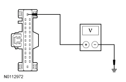
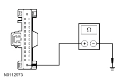
When DTC U3000:49 is set because the module has reached a third threshold and the BCM-B has permanently disabled an output, a measurement using a digital multimeter of the affected output circuit is required to make sure the fault condition no longer exists.
This pinpoint test is intended to diagnose the following:
| Test Step | Result / Action to Take |
|---|---|
| H1 REVIEW THE DTCs | |
NOTICE: First follow the necessary diagnostics to resolve DTC U1000:00 and any other present DTCs (ignoring U3000:49). DTC U1000:00 is only present when there is another DTC due to software or circuitry issues that must be resolved before another self-test is run. DTC U3000:49 is only present once the final threshold has been met. Failure to correct the fault condition first may cause damage to the new BCM-B , resulting in a repeat repair. | Yes
REFER to the Body Control Module B (BCM-B) DTC chart in this section. After the repair, GO to H2 . No GO to H2 . |
| H2 REPEAT THE BCM-B SELF-TEST | |
| Yes
INSTALL a new BCM-B . REFER to Body Control Module B (BCM-B) in this section. TEST the system for normal operation. No The system is operating correctly at this time. The circuit short has been repaired. |
Pinpoint Test I: DTC U3003:62
Refer to Wiring Diagrams Cell 89 , Interior Lamps for schematic and connector information.
This pinpoint test is intended to diagnose the following:
NOTICE: Use the correct probe adapter(s) when making measurements. Failure to use the correct probe adapter(s) may damage the connector.
NOTE: Failure to disconnect the battery when instructed results in false resistance readings. Refer to Section 414-01 .
NOTE: DTC U3003:62 may be stored in the module memory due to previous battery charging or vehicle jump starting events.
| Test Step | Result / Action to Take |
|---|---|
| I1 RECHECK THE BCM-B DTCs | |
| Yes
GO to I2 . No The system is operating normally at this time. The DTC may have been set due to a previous low battery voltage condition, during battery charging or while jump starting the vehicle. |
| I2 CHECK FOR CHARGING SYSTEM DTCs IN THE PCM | |
| Yes
REFER to Section 414-00 . No GO to I3 . |
| I3 CHECK FOR DTCs B1317, B1318 B1676, P0563 OR U3003:62 SET IN OTHER MODULES | |
| Yes
REFER to Section 414-00 to diagnose the charging system condition. No GO to I4 . |
| I4 CHECK THE BATTERY VOLTAGE | |
| Yes
REFER to Section 414-00 to diagnose an overcharging condition. No GO to I5 . |
| I5 CHECK THE BATTERY CONDITION AND STATE OF CHARGE | |
| Yes
GO to I6 . No REFER to Section 414-00 . |
| I6 CHECK THE BCM-B VOLTAGE PID | |
| Yes
GO to I9 . No GO to I7 . |
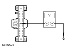
| I7 CHECK THE BCM-B VOLTAGE SUPPLY | |
 | Yes
GO to I8 . No REPAIR circuit SBB18 (YE/RD) for high resistance. CLEAR the DTC. REPEAT the self-test. |
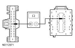
| I8 CHECK THE BCM-B GROUND CIRCUIT FOR HIGH RESISTANCE | |
 | Yes
GO to I9 . No REPAIR circuit GD110 (BK/WH) for high resistance. CLEAR the DTC. REPEAT the self-test. |
| I9 CHECK FOR CORRECT BCM-B OPERATION | |
| Yes
INSTALL a new BCM-B . REFER to Body Control Module B (BCM-B) in this section. TEST the system for normal operation. No The system is operating correctly at this time. The concern may have been caused by a loose or corroded connector. |