SECTION 205-00: Driveline System — General Information
2014 Mustang Workshop Manual
DIAGNOSIS AND TESTING
Procedure revision date: 01/07/2013

Driveline System


Special Tool(s)
Clamp Plate, Driveshaft
205-320 (T92L-4851-C)
Dial Indicator Gauge with Holding Fixture
100-D002 (D78P-4201-B) or equivalent
Gauge, Differential (Traction-Lok®)
205-385 (T97T-4205-B)
Runout Gauge, Drive Pinion Flange
205-319 (T92L-4851-B)

Material
Item Specification
Additive Friction Modifier
XL-3 (US); CXL-3 (Canada)
EST-M2C118-A
Motorcraft® High Contrast Hypoid Gear Marking Compound
XG-14
Motorcraft® SAE 75W-140 Synthetic Rear Axle Lubricant
XY-75W140-QL (US); CXY-75W140-1L (Canada)
WSL-M2C192-A and GL-5
Motorcraft® SAE 75W-85 Premium Synthetic Hypoid Gear Lubricant
XY-75W85-QL
WSS-M2C942-A
Threadlock 262
TA-26
WSK-M2G351-A6
 

Principles of Operation

The driveline system enables the power generated by the engine and transferred through the transmission to place the vehicle in motion. Rotational torque received from the transmission is delivered to the rear drive axle by way of the driveshaft. The U-joints or CV joints at the ends of the shafts allow the shafts to rotate smoothly in an allowable angle plane. The rotational torque is introduced into the axle drive pinion which drives the differential ring gear. The ring gear is bolted to the differential case flange on the differential. The differential divides the torque between the right and left axle shaft while permitting the axle shafts to turn at different speeds when required, such as when cornering.


Inspection and Verification

  1. Verify the customer concern.
  1. Visually inspect for obvious signs of mechanical damage.


  Visual Inspection Chart

Mechanical
  • U-joints
  • CV joints
  • Center bearings
  • Driveshaft tubes
  • Mounting brackets
  • Flanges
  • Housing and cover damage
  • Differential bearings
  • Differential gear sets
  • Pinion bearings
  • Engine mounts
  • Transmission mounts

  1. If an obvious cause for an observed or reported concern is found, correct the cause (if possible) before proceeding to the next step.
  1. If the cause is not visually evident, verify the symptom and GO to Symptom Chart - Driveline or GO to Symptom Chart - NVH .
 

Symptom Chart — Driveline

 
Symptom Chart — Driveline
Condition Possible Sources Action
  • Traction-Lok® does not work in snow, mud or on ice
  • Differential
  • CARRY OUT the Traction-Lok® Differential Operation Check in this section. REPAIR as necessary. REFER to Section 205-02 .
  • Torsen® differential does not work in snow, mud or on ice
  • Differential
  • CARRY OUT the Torsen® Differential Operation Check in this section and REPAIR as necessary. For REPAIRS, REFER to Section 205-02 .
  • Lubricant leaking from the pinion seal, axle shaft oil seals or support arm to the housing
  • Vent
  • Damage in the seal contact area or dust slinger on the pinion flange dust shield
  • CLEAN the axle housing vent.
  • INSTALL a new pinion flange and the pinion seal if damage is found.
  • Differential side gears/pinion gears are scored
  • Insufficient lubrication
  • INSTALL new gears. REFER to Section 205-02 . FILL the axle to specification.
    • Incorrect or contaminated lubricant type
    • INSTALL new gears. REFER to Section 205-02 . CLEAN and REFILL the axle to specification.
    • Axle overheating
    • Lubricant level too low
    • CHECK the lubricant level. FILL the axle to specification.
      • Incorrect or contaminated lubrication type
      • INSPECT the axle for damage. REPAIR as necessary. CLEAN and REFILL the axle to specification.
        • Bearing preload adjusted too tight
        • CHECK the ring and pinion for damage. INSPECT the ring and pinion wear pattern. ADJUST the preload as necessary.
          • Excessive gear wear
          • INSPECT all the axle gears for wear or damage. INSTALL new components as necessary.
            • Incorrect ring gear backlash
            • INSPECT the ring gear for scoring. INSPECT the ring and pinion wear pattern. ADJUST the ring gear backlash as necessary.
              • Differential oil cooler inoperative (vehicles with Track Pack option)
              • RETRIEVE and RECORD all PCM DTCs. REFER to the Differential Cooler DTC Chart. If there are no DTCs present, GO to Pinpoint Test D .
              • Broken gear teeth on the ring gear or pinion
              • Overloading the vehicle
               

              Symptom Chart — NVH

               
              Symptom Chart — NVH

              NOTE: NVH symptoms should be identified using the diagnostic tools that are available. For a list of these tools, an explanation of their uses and a glossary of common terms, refer to Section 100-04 . Since it is possible any one of multiple systems may be the cause of a symptom, it may be necessary to use a process of elimination type of diagnostic approach to pinpoint the responsible system. If this is not the causal system for the symptom, refer back to Section 100-04 for the next likely system and continue diagnosis.

              Condition Possible Sources Action
              • Axle howling or whine
              • Axle lubricant low
              • CHECK the lubricant level. FILL the axle to specification. REFER to Section 205-02 .
                • Tuned dampers missing or incorrectly installed
                • REFER to the TSB and follow the procedure outlined.
                  • Axle housing damage
                  • INSPECT the axle housing for damage. REPAIR or INSTALL a new axle as necessary. REFER to Section 205-02 .
                    • Damaged or worn wheel hub bearings
                    • CHECK for abnormal rear wheel bearing play or roughness. INSTALL a new wheel bearing as necessary. REFER to Section 205-02 .
                      • Damaged or worn differential ring and pinion
                      • INSPECT and INSTALL a new differential ring and pinion as necessary. REFER to Section 205-02 .
                        • Damaged or worn differential side or pinion bearings
                        • INSPECT and INSTALL new differential side or pinion bearings as necessary. REFER to Section 205-02 .
                        • Driveline clunk — loud clunk when shifting from REVERSE to DRIVE
                        • Incorrect axle lubricant level
                        • CHECK the lubricant level. FILL the axle to specification. REFER to Section 205-02 .
                          • Excessive backlash in the axle
                          • CHECK the ring gear backlash. REPAIR as necessary. REFER to Section 205-02 .
                            • Damaged or worn pinion bearings
                            • REPAIR or INSTALL new pinion bearings as necessary. REFER to Section 205-02 .
                              • Damaged or worn U-joints
                              • INSPECT the U-joints for wear or damage. INSTALL new U-joints or driveshaft as necessary. REFER to Section 205-01 .
                              • Driveline clunk — occurs as the vehicle starts to move forward following a stop
                              • Worn driveshaft CV joint or U-joints
                              • INSPECT the CV joint and U-joints for wear. INSTALL a new driveshaft or U-joints as necessary. REFER to Section 205-01 .
                                • Loose axle mount
                                • CHECK the axle for loose bolts. TIGHTEN to specification. REFER to Section 205-02 .
                                • High pitched chattering — noise from the axle when the vehicle is turning
                                • Incorrect or contaminated lubricant
                                • CHECK the vehicle by driving in tight circles (5 clockwise, 5 counterclockwise). FLUSH and REFILL with the specified rear axle lubricant and friction modifier as necessary.
                                  • Damaged or worn differential (differential side gears and pinion gears)
                                  • REPAIR or INSTALL new differential side gears or pinion gears as necessary. REFER to Section 205-02 .
                                  • Rumble or boom — noise occurs at coast/deceleration, usually driveshaft speed-related and noticeable over a wide range of speeds
                                  • Excessive driveshaft runout and/or driveshaft is out-of-balance
                                    • Binding or seized U-joints
                                    • ROTATE the driveshaft and CHECK for binding or seized U-joints. INSTALL new U-joints or driveshaft as necessary. REFER to Section 205-01 .
                                    • Grunting — normally associated with a shudder experienced during acceleration from a complete stop
                                    • Binding driveshaft CV joint
                                    • INSPECT the driveshaft CV joint for binding. INSTALL a new driveshaft as necessary. REFER to Section 205-01 .
                                      • Loose axle mount bolts or suspension fasteners
                                      • INSPECT the rear suspension and axle. TIGHTEN the fasteners to specification. REFER to Section 205-02 .
                                      • Howl — can occur at various speeds and driving conditions. Affected by acceleration and deceleration
                                      • Incorrect ring and pinion contact, incorrect bearing preload or gear damage
                                      • Chuckle — heard at coast/deceleration. Also described as a knock
                                      • Incorrect ring and pinion contact or damaged teeth on the coast side of the ring and pinion
                                      • Knock — noise occurs at various speeds. Not affected by acceleration or deceleration
                                      • Gear tooth damage to the drive side of the ring and pinion
                                      • Scraping noise — a continuous low pitched noise starting at low speeds
                                      • Worn or damaged pinion bearings
                                      • INSPECT and REPAIR or INSTALL new pinion bearings. REFER to Section 205-02 .
                                      • Driveline shudder — occurs during acceleration from a slow speed or stop
                                      • Incorrect transmission crossmember orientation
                                      • CHECK for correct orientation. REINSTALL if necessary. REFER to Section 502-00 .
                                        • Center bearing spacer missing or incorrectly installed
                                        • CHECK for correct installation of center bearing spacer. REFER to Section 205-01 .
                                          • Drive axle assembly mispositioned
                                          • CHECK the axle mounts and the rear suspension for damage or wear. REPAIR as necessary. REFER to Section 205-02 .
                                            • Loose axle bolts
                                            • CHECK the axle for loose bolts. TIGHTEN the bolts to specification. REFER to Section 205-02 .
                                              • Driveline angles out of specification
                                                • U-joints binding or seized
                                                • ROTATE the driveshaft and CHECK for binding or seized U-joints. INSTALL new U-joints or driveshaft as necessary. REFER to Section 205-01 .
                                                  • Binding or damaged driveshaft CV joint
                                                  • INSPECT the driveshaft CV joint for binding or damage. INSTALL a new driveshaft as necessary. REPAIR as necessary. REFER to Section 205-01 .
                                                  • Driveline vibration — occurs at cruising speeds
                                                  • Missing weights or damage to driveshaft
                                                  • INSPECT the driveshaft. INSTALL a new driveshaft as necessary. REFER to Section 205-01 .
                                                    • Worn U-joints
                                                    • CHECK for wear or incorrect seating. INSTALL new U-joints or driveshaft as necessary. REFER to Section 205-01 .
                                                      • Misalignment of yellow dot on driveshaft-to-yellow dot on pinion flange plus or minus 1 bolt hole
                                                      • REINSTALL driveshaft with yellow dots aligned plus or minus 1 bolt hole. REFER to Section 205-01 .
                                                        • Worn or damaged driveshaft center bearing support
                                                        • CHECK the insulator for damage or wear. ROTATE the driveshaft and CHECK for rough operation. INSTALL a new driveshaft as necessary. REFER to Section 205-01 .
                                                          • Loose axle pinion flange bolts
                                                          • INSPECT the axle pinion flange. TIGHTEN the pinion flange bolts to specification. REFER to Section 205-01 .
                                                            • Excessive axle pinion flange runout
                                                            • CHECK the pinion flange runout. REPAIR as necessary. REFER to Pinion Flange Runout Check in this section.
                                                              • Excessive transmission flange runout
                                                              • CHECK the transmission flange runout. REPAIR as necessary. REFER to Specifications in this section.
                                                                • Binding or damaged driveshaft CV joint
                                                                • INSPECT the driveshaft CV joint for binding or damage. INSTALL a new driveshaft as necessary. REFER to Section 205-01 .
                                                                  • Excessive driveshaft runout and/or driveshaft out-of-balance
                                                                    • Driveline angles out of specification
                                                                      • Transmission mount not centered
                                                                      • NEUTRALIZE the transmission mount. REFER to the Transmission Crossmember procedure in Section 502-00 .
                                                                       

                                                                      Analysis of Leakage

                                                                      Clean the leaking area enough to identify the exact source.

                                                                      A plugged axle housing vent can cause excessive pinion seal lip wear due to internal pressure buildup.

                                                                      Verify the lubricant level is at specification.

                                                                      Axle Vent

                                                                      A plugged axle vent causes excessive seal lip wear due to internal pressure buildup. If a leak occurs, check the axle vent. If the axle vent cannot be cleared, install a new axle vent.

                                                                      Drive Pinion Seal

                                                                      Leaks at the drive pinion seal originate from the following causes:

                                                                      Any damage to the seal bore (dings, dents, gouges or other imperfections) distorts the seal casing and allows leakage past the outer edge of the drive pinion seal.

                                                                      The drive pinion seal can be torn, cut or gouged if it is not installed correctly. The spring that holds the drive pinion seal against the pinion flange may be knocked out and allow fluid to pass the lip.

                                                                      Metal chips trapped at the sealing lip can cause oil leaks. These can cause a wear groove on the drive pinion flange and result in drive pinion seal wear.

                                                                      When a drive pinion seal leak occurs, install a new drive pinion seal and check the axle vent to make sure it is clean and free of foreign material.

                                                                      Install a new drive pinion flange if any of these conditions exist.

                                                                      Drive Pinion Nut

                                                                      NOTICE: Install the drive pinion nut to the correct torque specifications or damage to the differential components may occur.

                                                                      On some high-mileage vehicles, oil may leak through the threads of the drive pinion nut. This condition can be corrected by installing a new drive pinion nut and applying threadlock on the threads and nut face.

                                                                      Differential Seals

                                                                      NOTICE: When installing shafts, do not allow splines to contact seals during installation or damage to the seals may occur.

                                                                      Differential housing seals are susceptible to the same types of damage as drive pinion seals if incorrectly installed. The seal bore must be clean and the lip handled carefully to avoid cutting or tearing it. The seal journal surface must be free of nicks, gouges and rough surface texture.

                                                                      For information on differential seals, refer to Section 205-02 .


                                                                      Component Tests


                                                                      Traction-Lok® Differential Operation Check

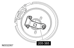
                                                                      A Traction-Lok® differential can be checked for correct operation without removing it from the rear axle housing.

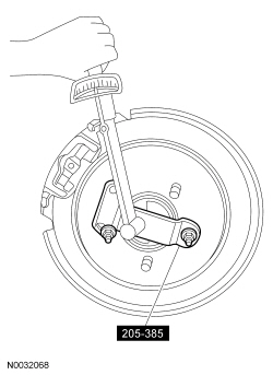
                                                                      Raise and remove only one rear wheel. Install the Differential Gauge on the wheel bolts.

                                                                      Use a torque wrench with the capacity of at least 271 Nm (200 lb-ft) to rotate the axle shaft. Make sure the transmission is in NEUTRAL, and that one rear wheel is on the floor while the other rear wheel is raised off the floor. The breakaway torque required to start rotation must be at least 27 Nm (20 lb-ft). The initial breakaway torque may be higher than the continuous turning torque.

                                                                      The axle shaft must turn with even pressure throughout the check without slipping or binding. If the torque reading is less than specified, check the differential case for incorrect assembly.


                                                                      Traction-Lok® Differential Check Road Test

                                                                      1. Place one wheel on a dry surface and the other wheel on ice, mud or snow.
                                                                      1. Gradually open the throttle to obtain maximum traction prior to break away. The ability to move the vehicle demonstrates correct performance of a Traction-Lok® rear axle assembly.
                                                                      1. When starting with one wheel on an excessively slippery surface, a slight application of the parking brake may be necessary to help energize the Traction-Lok® feature of the differential. Release the brake when traction is established. Use light throttle on starting to provide maximum traction.
                                                                      1. If, with unequal traction, both wheels slip, the limited slip rear axle has done all it can possibly do.
                                                                      1. In extreme cases of differences in traction, the wheel with the least traction may spin after the Traction-Lok® has transferred as much torque as possible to the non-slipping wheel.
                                                                       

                                                                      Torsen® Differential Check Road Test

                                                                      1. Place one wheel on a dry surface and the other wheel on ice, mud or snow.
                                                                      1. Gradually open the throttle to obtain maximum traction prior to break away. The ability to move the vehicle demonstrates correct performance of a Torsen® rear axle assembly.
                                                                      1. When starting with one wheel on an excessively slippery surface, a slight application of the parking brake may be necessary to help energize the Torsen® feature of the differential. Release the brake when traction is established. Use light throttle on starting to provide maximum traction.
                                                                      1. If, with unequal traction, both wheels slip, the limited slip rear axle has done all it can possibly do.
                                                                      1. In extreme cases of differences in traction, the wheel with the least traction may spin after the Torsen® has transferred as much torque as possible to the non-slipping wheel.
                                                                       

                                                                      Tooth Contact Pattern Check — Gearset

                                                                      1. To check the gear tooth contact, paint the gear teeth with the special marking compound. A mixture that is too wet will run and smear; a mixture that is too dry cannot be pressed out from between the teeth.
                                                                      1. Use a box wrench on the ring gear bolts as a lever to rotate the ring gear several complete revolutions in both directions or until a clear gear tooth contact pattern is obtained.
                                                                      1. Certain types of gear tooth contact patterns on the ring gear indicate incorrect adjustment. Incorrect adjustment can be corrected by readjusting the ring gear or the pinion.

                                                                      Contact Pattern Location

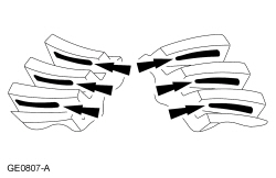
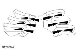
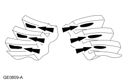
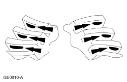
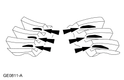
                                                                      In general, desirable ring gear tooth patterns must have the following characteristics:

                                                                      Acceptable Ring Gear Tooth Patterns For All Axles


                                                                      Correct Backlash With a Thinner Pinion Position Shim Required


                                                                      Correct Backlash With a Thicker Pinion Position Shim


                                                                      Correct the Pinion Position Shim That Requires a Decrease in Backlash


                                                                      Correct Pinion Position Shim That Requires an Increase in Backlash