
POM6411 or equivalent

NUD105-R025D or equivalent

FLU77-4 or equivalent

105-R0110

SECTION 206-09: Anti-Lock Brake System (ABS) and Stability Control
| 2014 Mustang Workshop Manual
|
DIAGNOSIS AND TESTING
| Procedure revision date: 01/07/2013
|
| Backprobe Pins
POM6411 or equivalent |
| Flex Probe Kit
NUD105-R025D or equivalent |
| Fluke 77-IV Digital Multimeter
FLU77-4 or equivalent |
| Rotunda Active Wheel Speed Sensor Tester
105-R0110 |
|
Vehicle Communication Module (VCM) and Integrated Diagnostic System (IDS) software with appropriate hardware, or equivalent scan tool
|
Principles of Operation
Anti-Lock Brake System
The ABS module continuously monitors brake pedal input, lateral vehicle motion and the rotational speed of each wheel. The PCM sends the brake pedal switch information to the ABS module over the High Speed Controller Area Network (HS-CAN) while the Restraints Control Module (RCM) sends lateral acceleration sensor information to the ABS module over a private HS-CAN . Wheel speed information is retrieved by the ABS module using 4 active wheel speed sensors, one for each wheel. When the ABS module detects an impending wheel lock during a braking event, the ABS module modulates brake pressure to the appropriate brake caliper(s) by opening and closing the appropriate solenoid valves inside the Hydraulic Control Unit (HCU) while the hydraulic pump motor is activated. Once the affected wheel(s) return to the desired speed, the ABS module returns the solenoid valves in the HCU to their normal position.
The ABS module has 2 self-test options, one is carried out using a scan tool and the other is carried out when the ABS is initialized (ignition ON). During either self test the ABS module carries out a preliminary electrical check of the system sensors and activates the hydraulic pump motor for approximately one-half second. During this time, a buzzing or humming noise may be heard and a vibration may be felt in the brake pedal and is a normal condition. During the module initialized self test, the pump motor check is carried out at approximately 16 km/h (10 mph). Any malfunction detected in the system causes the module to set a DTC, disable the ABS function and send a message over the HS-CAN to the Instrument Panel Cluster (IPC) to illuminate the ABS warning indicator. However, the base hydraulic power-assist braking system will function normally.
Electronic Brake Distribution (EBD)
On initial application of the brake pedal, full pressure is applied to the rear brakes. The ABS module then uses wheel speed input to calculate an estimated rate of deceleration. Once vehicle deceleration exceeds a predetermined threshold, the ABS module closes the appropriate isolation valves in the HCU to hold the rear brake pressure constant while allowing the front brake pressure to build. This creates a balanced braking condition between the front and rear wheels and minimizes the chance of rear wheel lockup during hard braking. As the vehicle decelerates, the valves are opened to increase the rear brake pressure in proportion to the front brake pressure. A slight bump sensation may be felt in the brake pedal when EBD is active. If ABS is disabled due to DTCs being present in the ABS module, EBD continues to function unless the DTCs are for wheel speed sensors or the HCU . When EBD is disabled, the ABS warning indicator, the red brake warning light, stability/traction control indicator (sliding car icon) and the stability/traction control OFF indicator (sliding car OFF icon) illuminate.
AdvanceTrac®
The AdvanceTrac® system consists of the traction control function and the Electronic Stability Control (ESC) function.
The ABS module continuously monitors and compares the rotational speed of the drive wheels in relation to the non-driven wheels. When the drive wheels begin to spin faster than the non-driven wheels, the ABS module modulates brake pressure to the appropriate brake caliper(s) by opening and closing the appropriate solenoid valves inside the HCU while the hydraulic pump motor is activated. At the same time, the ABS module sends a message over the HS-CAN that a traction event is taking place. When the PCM receives this message, it assists with traction control by adjusting engine timing and decreasing fuel injector pulses. When the IPC receives this message, it flashes the sliding car icon. Once the driven wheel speed returns to the desired speed, the ABS module returns the solenoid valves in the HCU to their normal position, deactivates the hydraulic pump motor and sends another message over the HS-CAN indicating that the event has ended. The PCM returns engine timing and fuel injectors to normal operation and the IPC extinguishes the sliding car icon. After the vehicle speed exceeds 100 km/h (62.1 mph), traction control is accomplished only through the PCM torque control.
The traction control system can be disabled by the driver using the stability/traction control switch. When the driver disables the traction control function, the IPC communicates traction control system status to the ABS module via the HS-CAN . The ABS module takes no further action in regards to traction control until the driver activates the function or until the ignition is cycled from OFF to ON. The ABS module disables the traction control function if there are any wheel speed sensor or solenoid valve DTCs present in the ABS module. The traction control function is also disabled if there is a communication error between the ABS module and the PCM. When the traction control function is disabled, the ABS module sends a message to the IPC to illuminate the sliding car OFF icon.
The ABS module continuously monitors the vehicle motion relative to the intended course. This is done by using sensors to compare the steering wheel input and the yaw rate sensor input with that of the actual vehicle motion. The Power Steering Control Module (PSCM) sends the steering wheel angle and rate of change information to the ABS module over the HS-CAN while the RCM sends yaw rate sensor information to the ABS module over a private HS-CAN . If the ABS module determines from the inputs that the vehicle is unable to travel in the intended direction, the ABS module modulates brake pressure to the appropriate brake caliper(s) by opening and closing the appropriate solenoid valves inside the HCU while the hydraulic pump motor is activated. At the same time, the ABS module sends a message over the HS-CAN that a vehicle stability event is taking place. When the PCM receives this message, it assists with vehicle control by adjusting engine timing and decreasing fuel injector pulses. When the IPC receives this message, it flashes the sliding car icon. Once the vehicle instability has been corrected, the ABS module returns the solenoid valves in the HCU to their normal position, deactivates the hydraulic pump motor and sends another message over the HS-CAN bus indicating that the event has ended. The PCM returns engine timing and fuel injectors to normal operation and the IPC extinguishes the sliding car icon.
The ESC function does not operate with the transmission in REVERSE. The ABS module disables the ESC function if there are any wheel speed sensor, stability sensor or steering angle sensor DTCs present in the ABS module. Also, if there is a communication error between the ABS module and the PSCM or the ESC function is disabled. When the ESC function is disabled, the ABS module sends a message over the HS-CAN to the IPC to illuminate the sliding car OFF icon.
Hill Start Assist
The ABS module uses the brake pedal switch message and ABS wheel speed sensor input to determine that the vehicle is at a complete stop. The transmission selector lever message lets the ABS module know that the vehicle is not being parked. The stability sensor messages from the RCM enable the ABS module to determine if the vehicle is on an incline greater than 5 degrees or greater than a 3% grade. The hill start assist function automatically engages once the above conditions have been met.
As the driver releases the brake pedal, the ABS module commands the HCU to close the isolation valves which will maintain the current brake system pressure, preventing the vehicle from rolling down the incline. Brake pressure is held for 2-3 seconds while the driver transitions to the accelerator pedal. As the accelerator pedal is pressed and the engine RPM increases, the ABS module gradually releases the brake pressure to make sure the vehicle is neither rolling back nor driving off until there is sufficient driving torque to move the vehicle.
Launch Control
The launch control system is controlled through the use of the launch control switch in the ride control switch pack and through the message center. When the launch control switch is pressed, a voltage signal is sent to the PCM. The PCM sends a message to the IPC over the HS-CAN indicating that the driver has requested launch control system activation. The driver then configures the launch control system through the message center, see the Owner's Literature for specific information. The launch control system will only activate when the AdvanceTrac® system is enabled or in Sport mode. Once activated, the launch control system will remain ON until the driver deactivates it, the system will not reset when the ignition is cycled.
Stability/Traction Control Switch
The stability/traction control switch is hardwired to the IPC . The IPC communicates switch status to the ABS module via the HS-CAN . The traction control switch allows the driver to control the AdvanceTrac® system. Traction control system status is indicated by the sliding car OFF icon and the message center in the IPC . The AdvanceTrac® system automatically restores to full functionality when the ignition is cycled from OFF to ON. There are 3 or 4 AdvanceTrac® system modes that can be selected, depending on the vehicle configuration and options.
The different modes of the AdvanceTrac® system can only be selected by starting with the AdvanceTrac® enabled. When a mode other than AdvanceTrac® enabled is selected, the sliding car OFF icon in the IPC illuminates. When the switch is pressed a single time, the traction control is disabled (traction control off mode); when the switch is pressed twice while the brake pedal is applied, AdvanceTrac® Sport mode is enabled; and when the switch is pressed and held for at least 5 seconds while the brake pedal is applied, the entire AdvanceTrac® system is disabled.
Pressing the switch once from any of the above-mentioned modes re-enables full AdvanceTrac® system operation. Also, at the start of every ignition cycle, full AdvanceTrac® system operation is present regardless of the mode selected on the previous ignition cycle (unless the vehicle is equipped with launch control and launch control is enabled). The conventional ABS cannot be disabled through the use of the stability/traction control switch.
Stability Control Sensors
The stability control sensors for the AdvanceTrac® system include the yaw rate sensor and the lateral accelerometer. The yaw rate sensor and the lateral accelerometer are able to detect and measure changes in vehicle direction that indicate the need for the ABS to make corrections that help prevent vehicle roll over or spin outs. The sensors are housed in the RCM which sends sensor information to the ABS module over the Controller Area Network (CAN). Install a new RCM if any of the sensors are damaged.
Steering Sensor
The steering sensor is used by the PSCM to determine speed and direction of the steering wheel. This information is transmitted to the ABS module along the HS-CAN . The sensor is attached to the Electronic Power Assist Steering (EPAS) column assembly and is not serviced separately.
ABS Module Calibration
When a new ABS module, HCU , or RCM is installed, the ABS module must be calibrated. The calibration procedure is required for the ABS module to learn the zero-position of the various ESC sensors and components.
If a DTC sets for any component of the ABS or AdvanceTrac® system, correct the fault condition and clear the DTC before carrying out the calibration procedure. The need to calibrate the ABS module is also indicated by the sliding car icon in the IPC flashing once every 2 seconds. The indicator flashes after clearing the DTCs associated with the ABS or AdvanceTrac® system.
To calibrate the ABS module, carry out the IVD Initialization sequence using the scan tool.
If a DTC is retrieved after calibration, refer to the ABS Module DTC Chart in this section.
Inspection and Verification
Visual Inspection Chart
| Mechanical | Electrical |
|---|---|
|
|
NOTE: Make sure to use the latest scan tool software release.
If the cause is not visually evident, connect the scan tool to the Data Link Connector (DLC).NOTE: The Vehicle Communication Module (VCM) LED prove-out confirms power and ground from the DLC are provided to the VCM .
If the scan tool does not communicate with the VCM :DTC Charts
NOTE: This module utilizes a 5-character DTC followed by a 2-character failure type code. The failure type code provides information about specific fault conditions such as opens or shorts to ground. Continuous Memory Diagnostic Trouble Codes (CMDTCs) have an additional 2-character DTC status code suffix to assist in determining DTC history.
ABS Module DTC Chart
| DTC | Description | Action |
|---|---|---|
| B11E8:16 | ABS Power Supply: Circuit Voltage Below Threshold | GO to Pinpoint Test A . |
| B11E8:17 | ABS Power Supply: Circuit Voltage Above Threshold | GO to Pinpoint Test B . |
| C0001:11 | TCS Control Channel "A" Valve 1: Circuit Short to Ground | This DTC indicates that part of the ABS module has failed internally. CLEAR the DTCs. REPEAT the self-test. If DTC C0001:11 returns, INSTALL a new ABS module. REFER to Anti-Lock Brake System (ABS) Module in this section. TEST the system for normal operation. |
| C0001:12 | TCS Control Channel "A" Valve 1: Circuit Short to Battery | This DTC indicates that part of the ABS module has failed internally. CLEAR the DTCs. REPEAT the self-test. If DTC C0001:12 returns, INSTALL a new ABS module. REFER to Anti-Lock Brake System (ABS) Module in this section. TEST the system for normal operation. |
| C0001:13 | TCS Control Channel "A" Valve 1: Circuit Open | This DTC indicates that part of the ABS module has failed internally. CLEAR the DTCs. REPEAT the self-test. If DTC C0001:13 returns, INSTALL a new ABS module. REFER to Anti-Lock Brake System (ABS) Module in this section. TEST the system for normal operation. |
| C0002:11 | TCS Control Channel "A" Valve 2: Circuit Short to Ground | This DTC indicates that part of the ABS module has failed internally. CLEAR the DTCs. REPEAT the self-test. If DTC C0002:11 returns, INSTALL a new ABS module. REFER to Anti-Lock Brake System (ABS) Module in this section. TEST the system for normal operation. |
| C0002:12 | TCS Control Channel "A" Valve 2: Circuit Short to Battery | This DTC indicates that part of the ABS module has failed internally. CLEAR the DTCs. REPEAT the self-test. If DTC C0002:12 returns, INSTALL a new ABS module. REFER to Anti-Lock Brake System (ABS) Module in this section. TEST the system for normal operation. |
| C0002:13 | TCS Control Channel "A" Valve 2: Circuit Open | This DTC indicates that part of the ABS module has failed internally. CLEAR the DTCs. REPEAT the self-test. If DTC C0002:13 returns, INSTALL a new ABS module. REFER to Anti-Lock Brake System (ABS) Module in this section. TEST the system for normal operation. |
| C0003:11 | TCS Control Channel "B" Valve 1: Circuit Short to Ground | This DTC indicates that part of the ABS module has failed internally. CLEAR the DTCs. REPEAT the self-test. If DTC C0003:11 returns, INSTALL a new ABS module. REFER to Anti-Lock Brake System (ABS) Module in this section. TEST the system for normal operation. |
| C0003:12 | TCS Control Channel "B" Valve 1: Circuit Short to Battery | This DTC indicates that part of the ABS module has failed internally. CLEAR the DTCs. REPEAT the self-test. If DTC C0003:12 returns, INSTALL a new ABS module. REFER to Anti-Lock Brake System (ABS) Module in this section. TEST the system for normal operation. |
| C0003:13 | TCS Control Channel "B" Valve 1: Circuit Open | This DTC indicates that part of the ABS module has failed internally. CLEAR the DTCs. REPEAT the self-test. If DTC C0003:13 returns, INSTALL a new ABS module. REFER to Anti-Lock Brake System (ABS) Module in this section. TEST the system for normal operation. |
| C0004:11 | TCS Control Channel "B" Valve 2: Circuit Short to Ground | This DTC indicates that part of the ABS module has failed internally. CLEAR the DTCs. REPEAT the self-test. If DTC C0004:11 returns, INSTALL a new ABS module. REFER to Anti-Lock Brake System (ABS) Module in this section. TEST the system for normal operation. |
| C0004:12 | TCS Control Channel "B" Valve 2: Circuit Short to Battery | This DTC indicates that part of the ABS module has failed internally. CLEAR the DTCs. REPEAT the self-test. If DTC C0004:12 returns, INSTALL a new ABS module. REFER to Anti-Lock Brake System (ABS) Module in this section. TEST the system for normal operation. |
| C0004:13 | TCS Control Channel "B" Valve 2: Circuit Open | This DTC indicates that part of the ABS module has failed internally. CLEAR the DTCs. REPEAT the self-test. If DTC C0004:13 returns, INSTALL a new ABS module. REFER to Anti-Lock Brake System (ABS) Module in this section. TEST the system for normal operation. |
| C0020:12 | ABS Pump Motor Control: Circuit Short To Battery | GO to Pinpoint Test C . |
| C0020:15 | ABS Pump Motor Control: Circuit Short To Battery Or Open | GO to Pinpoint Test C . |
| C0020:71 | ABS Pump Motor Control: Actuator Stuck | GO to Pinpoint Test C . |
| C0031:13 | Left Front Wheel Speed Sensor: Circuit Open | GO to Pinpoint Test D . |
| C0031:17 | Left Front Wheel Speed Sensor: Circuit Voltage Above Threshold | GO to Pinpoint Test D . |
| C0031:23 | Left Front Wheel Speed Sensor: Signal Stuck Low | GO to Pinpoint Test D . |
| C0031:2F | Left Front Wheel Speed Sensor: Signal Erratic | GO to Pinpoint Test E . |
| C0031:62 | Left Front Wheel Speed Sensor: Signal Compare Failure | GO to Pinpoint Test E . |
| C0034:13 | Right Front Wheel Speed Sensor: Circuit Open | GO to Pinpoint Test D . |
| C0034:17 | Right Front Wheel Speed Sensor: Circuit Above Threshold | GO to Pinpoint Test D . |
| C0034:23 | Right Front Wheel Speed Sensor: Signal Stuck Low | GO to Pinpoint Test D . |
| C0034:2F | Right Front Wheel Speed Sensor: Signal Erratic | GO to Pinpoint Test E . |
| C0034:62 | Right Front Wheel Speed Sensor: Signal Compare Failure | GO to Pinpoint Test E . |
| C0037:13 | Left Rear Wheel Speed Sensor: Circuit Open | GO to Pinpoint Test D . |
| C0037:17 | Left Rear Wheel Speed Sensor: Circuit Voltage Above Threshold | GO to Pinpoint Test D . |
| C0037:23 | Left Rear Wheel Speed Sensor: Signal Stuck Low | GO to Pinpoint Test D . |
| C0037:2F | Left Rear Wheel Speed Sensor: Signal Erratic | GO to Pinpoint Test E . |
| C0037:62 | Left Rear Wheel Speed Sensor: Signal Compare Failure | GO to Pinpoint Test E . |
| C003A:13 | Right Rear Wheel Speed Sensor: Circuit Open | GO to Pinpoint Test D . |
| C003A:17 | Right Rear Wheel Speed Sensor: Circuit Voltage Above Threshold | GO to Pinpoint Test D . |
| C003A:23 | Right Rear Wheel Speed Sensor: Signal Stuck Low | GO to Pinpoint Test D . |
| C003A:2F | Right Rear Wheel Speed Sensor: Signal Erratic | GO to Pinpoint Test E . |
| C003A:62 | Right Rear Wheel Speed Sensor Signal Compare Failure | GO to Pinpoint Test E . |
| C0040:72 | Brake Pedal Switch "A": Actuator Stuck Open | GO to Pinpoint Test F . |
| C0040:73 | Brake Pedal Switch "A": Actuator Stuck Closed | GO to Pinpoint Test F . |
| C0049:7B | Brake Fluid: Low Fluid Level | For low brake fluid level diagnosis. REFER to Section 413-01 . |
| C0061:00 | Lateral Acceleration Sensor: No Sub Type Information | This DTC indicates a concern with the lateral accelerometer sensor which is integral to the Restraints Control Module (RCM). REFER to Section 501-20B to diagnose all the RCM DTCs. If no RCM DTCs are present, GO to Pinpoint Test M in this section to diagnose the communication issue. |
| C0061:62 | Lateral Acceleration Sensor: Signal Compare Failure | This DTC indicates a concern with the lateral accelerometer sensor which is integral to the RCM . REFER to Section 501-20B to diagnose all the RCM DTCs. If no RCM DTCs are present, GO to Pinpoint Test M in this section to diagnose the communication issue. |
| C0061:65 | Lateral Acceleration Sensor: Signal Has Too Few Transitions/Events | This DTC indicates a concern with the lateral accelerometer sensor which is integral to the RCM . REFER to Section 501-20B to diagnose all the RCM DTCs. If no RCM DTCs are present, GO to Pinpoint Test M in this section to diagnose the communication issue. |
| C0061:67 | Lateral Acceleration Sensor: Signal Incorrect After Event | This DTC indicates a concern with the lateral accelerometer sensor which is integral to the RCM . REFER to Section 501-20B to diagnose all the RCM DTCs. If no RCM DTCs are present, GO to Pinpoint Test M in this section to diagnose the communication issue. |
| C0061:82 | Lateral Acceleration Sensor: Alive/Sequence Counter Incorrect/Not Updated | This DTC indicates a concern with the lateral accelerometer sensor which is integral to the RCM . REFER to Section 501-20B to diagnose all the RCM DTCs. If no RCM DTCs are present, GO to Pinpoint Test M in this section to diagnose the communication issue. |
| C0063:00 | Yaw Rate Sensor: No Sub Type Information | This DTC indicates a concern with the yaw rate sensor which is integral to the RCM . REFER to Section 501-20B to diagnose all the RCM DTCs. If no RCM DTCs are present, GO to Pinpoint Test M in this section to diagnose the communication issue. |
| C0063:62 | Yaw Rate Sensor: Signal Compare Failure | This DTC indicates a concern with the yaw rate sensor which is integral to the RCM . REFER to Section 501-20B to diagnose all the RCM DTCs. If no RCM DTCs are present, GO to Pinpoint Test M in this section to diagnose the communication issue. |
| C0063:65 | Yaw Rate Sensor: Signal Has Too Few Transitions/Events | This DTC indicates a concern with the yaw rate sensor which is integral to the RCM . REFER to Section 501-20B to diagnose all the RCM DTCs. If no RCM DTCs are present, GO to Pinpoint Test M in this section to diagnose the communication issue. |
| C0063:67 | Yaw Rate Sensor: Signal Incorrect After Event | This DTC indicates a concern with the yaw rate sensor which is integral to the RCM . REFER to Section 501-20B to diagnose all the RCM DTCs. If no RCM DTCs are present, GO to Pinpoint Test M in this section to diagnose the communication issue. |
| C0063:85 | Yaw Rate Sensor: Signal Above Allowable Range | This DTC indicates a concern with the yaw rate sensor which is integral to the RCM . REFER to Section 501-20B to diagnose all the RCM DTCs. If no RCM DTCs are present, GO to Pinpoint Test M in this section to diagnose the communication issue. |
| C0078:61 | Tire Diameter: Signal Calculation Failure | GO to Pinpoint Test E . |
| C0089:73 | TCS Disable Switch: Actuator Stuck Closed | GO to Pinpoint Test O . |
| C1A76:12 | Valve Relay: Circuit Short To Battery | This DTC indicates a concern in the ABS module. CLEAR the DTCs. CARRY OUT the ABS module self-test. RETRIEVE and RECORD any DTCs. If DTC C1A76:12 is retrieved again, INSTALL a new ABS module. REFER to Anti-Lock Brake System (ABS) Module in this section. TEST the system for normal operation. |
| C1A76:13 | Valve Relay: Circuit Open | This DTC indicates a concern in the ABS module. CLEAR the DTCs. CARRY OUT the ABS module self-test. RETRIEVE and RECORD any DTCs. If DTC C1A76:13 is retrieved again, INSTALL a new ABS module. REFER to Anti-Lock Brake System (ABS) Module in this section. TEST the system for normal operation. |
| C1A78:11 | Left Front Inlet Valve: Circuit Short To Ground | This DTC indicates a concern in the ABS module. CLEAR the DTCs. CARRY OUT the ABS module self-test. RETRIEVE and RECORD any DTCs. If DTC C1A78:11 is retrieved again, INSTALL a new ABS module. REFER to Anti-Lock Brake System (ABS) Module in this section. TEST the system for normal operation. |
| C1A78:12 | Left Front Inlet Valve: Circuit Short To Battery | This DTC indicates a concern in the ABS module . CLEAR the DTCs. CARRY OUT the ABS module self-test. RETRIEVE and RECORD any DTCs. If DTC C1A78:12 is retrieved again, INSTALL a new ABS module. REFER to Anti-Lock Brake System (ABS) Module in this section. TEST the system for normal operation. |
| C1A78:13 | Left Front Inlet Valve: Circuit Open | This DTC indicates a concern in the ABS module. CLEAR the DTCs. CARRY OUT the ABS module self-test. RETRIEVE and RECORD any DTCs. If DTC C1A78:13 is retrieved again, INSTALL a new ABS module. REFER to Anti-Lock Brake System (ABS) Module in this section. TEST the system for normal operation. |
| C1A79:11 | Left Front Outlet Valve: Circuit Short To Ground | This DTC indicates a concern in the ABS module. CLEAR the DTCs. CARRY OUT the ABS module self-test. RETRIEVE and RECORD any DTCs. If DTC C1A79:11 is retrieved again, INSTALL a new ABS module. REFER to Anti-Lock Brake System (ABS) Module in this section. TEST the system for normal operation. |
| C1A79:12 | Left Front Outlet Valve: Circuit Short To Battery | This DTC indicates a concern in the ABS module. CLEAR the DTCs. CARRY OUT the ABS module self-test. RETRIEVE and RECORD any DTCs. If DTC C1A79:12 is retrieved again, INSTALL a new ABS module. REFER to Anti-Lock Brake System (ABS) Module in this section. TEST the system for normal operation. |
| C1A79:13 | Left Front Outlet Valve: Circuit Open | This DTC indicates a concern in the ABS module . CLEAR the DTCs. CARRY OUT the ABS module self-test. RETRIEVE and RECORD any DTCs. If DTC C1A79:13 is retrieved again, INSTALL a new ABS module. REFER to Anti-Lock Brake System (ABS) Module in this section. TEST the system for normal operation. |
| C1A80:11 | Right Front Inlet Valve: Circuit Short To Ground | This DTC indicates a concern in the ABS module. CLEAR the DTCs. CARRY OUT the ABS module self-test. RETRIEVE and RECORD any DTCs. If DTC C1A80:11 is retrieved again, INSTALL a new ABS module. REFER to Anti-Lock Brake System (ABS) Module in this section. TEST the system for normal operation. |
| C1A80:12 | Right Front Inlet Valve: Circuit Short to Voltage | This DTC indicates a concern in the ABS module. CLEAR the DTCs. CARRY OUT the ABS module self-test. RETRIEVE and RECORD any DTCs. If DTC C1A80:12 is retrieved again, INSTALL a new ABS module. REFER to Anti-Lock Brake System (ABS) Module in this section. TEST the system for normal operation. |
| C1A80:13 | Right Front Inlet Valve: Circuit Open | This DTC indicates a concern in the ABS module. CLEAR the DTCs. CARRY OUT the ABS module self-test. RETRIEVE and RECORD any DTCs. If DTC C1A80:13 is retrieved again, INSTALL a new ABS module. REFER to Anti-Lock Brake System (ABS) Module in this section. TEST the system for normal operation. |
| C1A81:11 | Right Front Outlet Valve: Circuit Short To Ground | This DTC indicates a concern in the ABS module. CLEAR the DTCs. CARRY OUT the ABS module self-test. RETRIEVE and RECORD any DTCs. If DTC C1A81:11 is retrieved again, INSTALL a new ABS module. REFER to Anti-Lock Brake System (ABS) Module in this section. TEST the system for normal operation. |
| C1A81:12 | Right Front Outlet Valve: Circuit Short to Battery | This DTC indicates a concern in the ABS module . CLEAR the DTCs. CARRY OUT the ABS module self-test. RETRIEVE and RECORD any DTCs. If DTC C1A81:12 is retrieved again, INSTALL a new ABS module. REFER to Anti-Lock Brake System (ABS) Module in this section. TEST the system for normal operation. |
| C1A81:13 | Right Front Outlet Valve: Circuit Open | This DTC indicates a concern in the ABS module. CLEAR the DTCs. CARRY OUT the ABS module self-test. RETRIEVE and RECORD any DTCs. If DTC C1A81:13 is retrieved again, INSTALL a new ABS module. REFER to Anti-Lock Brake System (ABS) Module in this section. TEST the system for normal operation. |
| C1A82:11 | Left Rear Inlet Valve: Circuit Short To Ground | This DTC indicates a concern in the ABS module. CLEAR the DTCs. CARRY OUT the ABS module self-test. RETRIEVE and RECORD any DTCs. If DTC C1A82:11 is retrieved again, INSTALL a new ABS module. REFER to Anti-Lock Brake System (ABS) Module in this section. TEST the system for normal operation. |
| C1A82:12 | Left Rear Inlet Valve: Circuit Short to Battery | This DTC indicates a concern in the ABS module. CLEAR the DTCs. CARRY OUT the ABS module self-test. RETRIEVE and RECORD any DTCs. If DTC C1A82:12 is retrieved again, INSTALL a new ABS module. REFER to Anti-Lock Brake System (ABS) Module in this section. TEST the system for normal operation. |
| C1A82:13 | Left Rear Inlet Valve: Circuit Open | This DTC indicates a concern in the ABS module. CLEAR the DTCs. CARRY OUT the ABS module self-test. RETRIEVE and RECORD any DTCs. If DTC C1A82:13 is retrieved again, INSTALL a new ABS module. REFER to Anti-Lock Brake System (ABS) Module in this section. TEST the system for normal operation. |
| C1A83:11 | Left Rear Outlet Valve: Circuit Short To Ground | This DTC indicates a concern in the ABS module. CLEAR the DTCs. CARRY OUT the ABS module self-test. RETRIEVE and RECORD any DTCs. If DTC C1A83:11 is retrieved again, INSTALL a new ABS module. REFER to Anti-Lock Brake System (ABS) Module in this section. TEST the system for normal operation. |
| C1A83:12 | Left Rear Outlet Valve: Circuit Short to Battery | This DTC indicates a concern in the ABS module. CLEAR the DTCs. CARRY OUT the ABS module self-test. RETRIEVE and RECORD any DTCs. If DTC C1A83:12 is retrieved again, INSTALL a new ABS module. REFER to Anti-Lock Brake System (ABS) Module in this section. TEST the system for normal operation. |
| C1A83:13 | Left Rear Outlet Valve: Circuit Open | This DTC indicates a concern in the ABS module. CLEAR the DTCs. CARRY OUT the ABS module self-test. RETRIEVE and RECORD any DTCs. If DTC C1A83:13 is retrieved again, INSTALL a new ABS module. REFER to Anti-Lock Brake System (ABS) Module in this section. TEST the system for normal operation. |
| C1A84:11 | Right Rear Inlet Valve: Circuit Short To Ground | This DTC indicates a concern in the ABS module. CLEAR the DTCs. CARRY OUT the ABS module self-test. RETRIEVE and RECORD any DTCs. If DTC C1A84:11 is retrieved again, INSTALL a new ABS module. REFER to Anti-Lock Brake System (ABS) Module in this section. TEST the system for normal operation. |
| C1A84:12 | Right Rear Inlet Valve: Circuit Short to Battery | This DTC indicates a concern in the ABS module. CLEAR the DTCs. CARRY OUT the ABS module self-test. RETRIEVE and RECORD any DTCs. If DTC C1A84:12 is retrieved again, INSTALL a new ABS module. REFER to Anti-Lock Brake System (ABS) Module in this section. TEST the system for normal operation. |
| C1A84:13 | Right Rear Inlet Valve: Circuit Open | This DTC indicates a concern in the ABS module. CLEAR the DTCs. CARRY OUT the ABS module self-test. RETRIEVE and RECORD any DTCs. If DTC C1A84:13 is retrieved again, INSTALL a new ABS module. REFER to Anti-Lock Brake System (ABS) Module in this section. TEST the system for normal operation. |
| C1A85:11 | Right Rear Outlet Valve: Circuit Short To Ground | This DTC indicates a concern in the ABS module. CLEAR the DTCs. CARRY OUT the ABS module self-test. RETRIEVE and RECORD any DTCs. If DTC C1A85:11 is retrieved again, INSTALL a new ABS module. REFER to Anti-Lock Brake System (ABS) Module in this section. TEST the system for normal operation. |
| C1A85:12 | Right Rear Outlet Valve: Circuit Short To Battery | This DTC indicates a concern in the ABS module. CLEAR the DTCs. CARRY OUT the ABS module self-test. RETRIEVE and RECORD any DTCs. If DTC C1A85:12 is retrieved again, INSTALL a new ABS module. REFER to Anti-Lock Brake System (ABS) Module in this section. TEST the system for normal operation. |
| C1A85:13 | Right Rear Outlet Valve: Circuit Open | This DTC indicates a concern in the ABS module. CLEAR the DTCs. CARRY OUT the ABS module self-test. RETRIEVE and RECORD any DTCs. If DTC C1A85:13 is retrieved again, INSTALL a new ABS module. REFER to Anti-Lock Brake System (ABS) Module in this section. TEST the system for normal operation. |
| C1A98:54 | Yaw Rate Sensor: Missing Calibration | GO to Pinpoint Test G . |
| C1A99:14 | Pressure Sensor: Circuit Short To Ground Or Open | GO to Pinpoint Test H . |
| C1A99:17 | Pressure Sensor: Circuit Voltage Above Threshold | GO to Pinpoint Test H . |
| C1A99:2F | Pressure Sensor: Signal Erratic | GO to Pinpoint Test H . |
| C1A99:62 | Pressure Sensor: Signal Compare Failure | GO to Pinpoint Test H . |
| C1A99:65 | Pressure Sensor: Signal Has Too Few Transitions/Events | GO to Pinpoint Test H . |
| C1A99:67 | Pressure Sensor: Signal Incorrect After Event | GO to Pinpoint Test H . |
| C1B00:00 | Steering Angle Sensor: No Sub Type Information | This DTC sets when the ABS module receives invalid data from the Power Steering Control Module (PSCM) regarding the steering wheel angle sensor input. RETRIEVE and REPAIR all non-network DTCs in the PSCM . REFER to Section 211-00 . |
| C1B00:62 | Steering Angle Sensor: Signal Compare Failure | This DTC sets when the ABS module receives incorrect data from the PSCM regarding the steering wheel angle sensor input. RETRIEVE and REPAIR all non-network DTCs in the PSCM . REFER to Section 211-00 . |
| C1B00:63 | Steering Angle Sensor: Circuit/Component Protection Time-out | This DTC sets when the Yaw rate and stability sensors do not initialize after the vehicle has traveled 1000 meters (.65 miles) with vehicle speed above 75 km/h (45 mph). RETRIEVE and REPAIR all non-network DTCs in the PSCM . REFER to Section 211-00 . |
| C1B00:65 | Steering Angle Sensor: Signal Has Too Few Transitions/Events | This DTC sets when the Yaw rate sensor information changes but the steering wheel angle sensor data does not change. RETRIEVE and REPAIR all non-network DTCs in the PSCM . REFER to Section 211-00 . |
| C1B00:67 | Steering Angle Sensor: Signal Incorrect After Event | This DTC sets when the steering angle sensor exceeds its step limit. RETRIEVE and REPAIR all non-network DTCs in the PSCM . REFER to Section 211-00 . |
| C1B00:81 | Steering Angle Sensor: Invalid Serial Data Received | This DTC sets when the ABS module receives invalid data from the PSCM regarding the steering wheel angle sensor input. RETRIEVE and REPAIR all non-network DTCs in the PSCM . REFER to Section 211-00 . |
| C1B00:82 | Steering Angle Sensor: Alive/Sequence Counter Incorrect/Not Updated | This DTC sets when the ABS module receives invalid data from the PSCM regarding the steering wheel angle sensor input. RETRIEVE and REPAIR all non-network DTCs in the PSCM . REFER to Section 211-00 . |
| U0001:49 | High Speed CAN Communication Bus: Internal Electronic Failure | REFER to Section 418-00 to diagnose the network communication concern. |
| U0001:88 | High Speed CAN Communication Bus: Bus Off | REFER to Section 418-00 to diagnose the network communication concern. |
| U0100:00 | Lost Communication With ECM/PCM "A": No Sub Type Information | GO to Pinpoint Test I . |
| U0131:00 | Lost Communication With Power Steering Control Module: No Sub Type Information | GO to Pinpoint Test J . |
| U0151:00 | Lost Communication With Restraints Control Module: No Sub Type Information | GO to Pinpoint Test K . |
| U0155:00 | Lost Communication With Instrument Panel Cluster (IPC) Control Module: No Sub Type Information | GO to Pinpoint Test L . |
| U0401:00 | Invalid Data received From ECM/PCM "A": No Sub Type Information | This DTC sets when the ABS module receives invalid network data from the ECM/PCM. RETRIEVE and REPAIR all non-network DTCs in the PCM. REFER to Section 303-14 . |
| U0452:00 | Invalid Data received From Restraints Control Module: No Sub Type Information | This DTC sets when the ABS module receives invalid network data from the RCM . RETRIEVE and REPAIR all non-network DTCs in the RCM . REFER to Section 501-20B . |
| U1A00:49 | Private Communication Network: Internal Electronic Failure | GO to Pinpoint Test M . |
| U1A00:87 | Private Communication Network: Missing Message | GO to Pinpoint Test M . |
| U200A:1C | Control Module: Internal Power A Circuit Voltage Out of Range | DIAGNOSE all other DTCs first. If no other DTCs are present, INSTALL a new ABS module. REFER to Anti-Lock Brake System (ABS) Module in this section. TEST the system for normal operation. |
| U201A:57 | Control Module Main Calibration Data Invalid: Incompatible Software Component | CARRY OUT Programmable Module Installation (PMI) on the ABS module. CLEAR the DTCs. REPEAT the self-test. If U201A:57 is retrieved again, INSTALL a new ABS module. REFER to Anti-Lock Brake System (ABS) Module in this section. TEST the system for normal operation. |
| U2100:00 | Initial Configuration Not Complete: No Sub Type Information | CARRY OUT Programmable Module Installation (PMI) on the ABS module. CLEAR the DTCs. REPEAT the self-test. If U2100:00 is retrieved again, INSTALL a new ABS module. REFER to Anti-Lock Brake System (ABS) Module in this section. TEST the system for normal operation. |
| U2101:00 | Control Module Configuration Incompatible: No Sub Type Information | CARRY OUT PMI on the ABS module. CLEAR the DTCs. REPEAT the self-test. If U2101:00 is retrieved again, INSTALL a new ABS module. REFER to Anti-Lock Brake System (ABS) Module in this section. TEST the system for normal operation. |
| U3000:41 | Control Module: General Checksum Failure | DIAGNOSE all other DTCs first. If no other DTCs are present, INSTALL a new ABS module. REFER to Anti-Lock Brake System (ABS) Module in this section. TEST the system for normal operation. |
| U3000:43 | Control Module: Special Memory Failure | DIAGNOSE all other DTCs first. If no other DTCs are present, INSTALL a new ABS module. REFER to Anti-Lock Brake System (ABS) Module in this section. TEST the system for normal operation. |
| U3000:44 | Control Module: Data Memory Failure | DIAGNOSE all other DTCs first. If no other DTCs are present, INSTALL a new ABS module. REFER to Anti-Lock Brake System (ABS) Module in this section. TEST the system for normal operation. |
| U3000:45 | Control Module: Program Memory Failure | DIAGNOSE all other DTCs first. If no other DTCs are present, INSTALL a new ABS module. REFER to Anti-Lock Brake System (ABS) Module in this section. TEST the system for normal operation. |
| U3000:47 | Control Module: Watchdog Safety Failure | DIAGNOSE all other DTCs first. If no other DTCs are present, INSTALL a new ABS module. REFER to Anti-Lock Brake System (ABS) Module in this section. TEST the system for normal operation. |
| U3000:49 | Control Module: Internal Electronic Failure | DIAGNOSE all other DTCs first. If no other DTCs are present, INSTALL a new ABS module. REFER to Anti-Lock Brake System (ABS) Module in this section. TEST the system for normal operation. |
| U3000:4B | Control Module: Over Temperature | DIAGNOSE all other DTCs first. If no other DTCs are present, INSTALL a new ABS module. REFER to Anti-Lock Brake System (ABS) Module in this section. TEST the system for normal operation. |
| U3002:62 | Vehicle Identification Number: Signal Compare Failure | GO to Pinpoint Test N . |
Symptom Chart
| Condition | Possible Sources | Action |
|---|---|---|
|
|
|
|
|
|
|
|
|
|
|
|
|
ABS module not calibrated |
|
|
|
|
|
|
|
|
|
|
|
| |
|
|
|
Pinpoint Tests
Pinpoint Test A: DTC B11E8:16
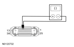
Refer to Wiring Diagrams Cell 42 , Vehicle Dynamic Systems for schematic and connector information.
NOTICE: Use the correct probe adapter(s) when making measurements. Failure to use the correct probe adapter(s) may damage the connector
NOTE: Failure to disconnect the battery when instructed results in false resistance readings. Refer to Section 414-01 .
| Test Step | Result / Action to Take | ||||||||
|---|---|---|---|---|---|---|---|---|---|
| A1 RECHECK THE ABS MODULE DTCs | |||||||||
| Yes
GO to A2 . No The system is operating correctly at this time. The DTC may have been set due to a previous low battery voltage condition. | ||||||||
| A2 CHECK FOR CHARGING SYSTEM DTCs IN THE PCM | |||||||||
| Yes
REFER to Section 414-00 . No GO to A3 . | ||||||||
| A3 CHECK THE BATTERY CONDITION AND STATE OF CHARGE | |||||||||
| Yes
GO to A4 . No REFER to Section 414-01 . | ||||||||
| A4 CHECK THE ABS MODULE VOLTAGE SUPPLY | |||||||||
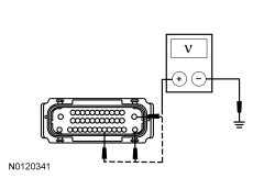 | Yes
GO to A5 . No VERIFY the fuses are OK. If OK, REPAIR the circuit in question for an open. If not OK, REFER to the Wiring Diagrams Manual to identify the possible causes of the short circuit. CLEAR the DTC. REPEAT the self-test. | ||||||||
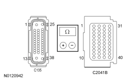
| A5 CHECK THE ABS MODULE GROUND CIRCUIT | |||||||||
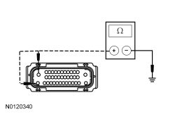 | Yes
GO to A6 . No REPAIR circuit GD120 (BK/GN) for open circuit. CLEAR the DTCs. REPEAT the self-test. | ||||||||
| A6 CHECK THE ABS MODULE GROUND EYELET AT THE CHASSIS | |||||||||
| Yes
GO to A7 . No The concern was caused by a loose or corroded connector. CLEAR the DTCs. REPEAT self-test. | ||||||||
| A7 CHECK FOR CORRECT ABS MODULE OPERATION | |||||||||
| Yes
INSTALL a new ABS module. REFER to Anti-Lock Brake System (ABS) Module in this section. TEST the system for normal operation. No The system is operating correctly at this time. The concern may have been caused by a loose or corroded connector. |
Pinpoint Test B: DTC B11E8:17
Refer to Wiring Diagrams Cell 42 , Vehicle Dynamic Systems for schematic and connector information.
NOTICE: Use the correct probe adapter(s) when making measurements. Failure to use the correct probe adapter(s) may damage the connector.
NOTE: DTC B11E8:17 may be stored in the module memory due to past battery charging or vehicle jump starting events.
| Test Step | Result / Action to Take |
|---|---|
| B1 CHECK FOR DTC B11E8:17, B1317, B1676, P0563 (PCM) OR U3003:17 SET IN OTHER MODULES | |
| Yes
REFER to Section 414-00 to diagnose an overcharging condition. No GO to B2 . |
| B2 CHECK THE BATTERY VOLTAGE | |
| Yes
REFER to Section 414-00 to diagnose an overcharging condition. No GO to B3 . |
| B3 RECHECK FOR DTC B11E8:17 | |
| Yes
INSTALL a new ABS module. REFER to Anti-Lock Brake System (ABS) Module in this section. TEST the system for normal operation. No The system is operating normally at this time. The DTC may have been set previously during battery charging or while jump starting the vehicle. |
Pinpoint Test C: DTCs C0020:12, C0020:15 and C0020:71
Refer to Wiring Diagrams Cell 42 , Vehicle Dynamic Systems for schematic and connector information.
When the ignition key is turned to the ON position, the ABS module commands the Hydraulic Control Unit (HCU) pump on for 100 ms (±6 ms) and is then commanded off. After 6 ms, the ABS module reads the voltage that is being generated by the HCU pump. If the voltage indicates the motor is spinning at less than 500 rpm, there may be a locked motor. If this condition is detected 4 times, DTC C0020:12 sets. The pump motor is checked for an open circuit 2 seconds after the most recent successful pump motor off command. If the pump motor feedback remains greater than 0.75 volt for more than 50 ms (±6 ms) after these conditions have been met, DTC C0020:15 sets.
NOTICE: Use the correct probe adapter(s) when making measurements. Failure to use the correct probe adapter(s) may damage the connector.
NOTE: Failure to disconnect the battery when instructed results in false resistance readings. Refer to Section 414-01 .
| Test Step | Result / Action to Take |
|---|---|
| C1 CHECK THE PUMP MOTOR (PMP_MOTOR) ACTIVE COMMAND | |
| Yes
GO to C2 . No TOGGLE the PMP_MOTOR active command OFF. GO to C3 . |
| C2 CHECK FOR FAULT REPEATABILITY | |
| Yes
GO to C3 . No The system is operating correctly at this time. The concern may have been caused by a loose or corroded connector. |
| C3 CHECK THE ABS MODULE GROUND EYELET AT THE CHASSIS | |
| Yes
GO to C4 . No The concern was caused by a loose or corroded connector. CLEAR the DTCs. REPEAT self-test. |
| C4 CHECK THE PUMP MOTOR VOLTAGE SUPPLY TO THE ABS MODULE | |
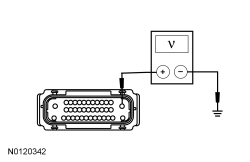 | Yes
GO to C5 . No VERIFY that BJB fuse 8 (40A) is OK. If OK, REPAIR circuit SBB08 (VT/RD). If not OK, REFER to the Wiring Diagrams manual to identify the cause of the circuit short. CLEAR the DTCs. REPEAT the self-test. |
| C5 CHECK THE ABS MODULE GROUND CIRCUITS FOR AN OPEN | |
| Yes
GO to C6 . No REPAIR circuit GD120 (BK/GN) for an open circuit. CLEAR the DTCs. REPEAT the self-test. |
| C6 CHECK FOR CORRECT ABS MODULE OPERATION | |
| Yes
INSTALL a new ABS module. REFER to Anti-Lock Brake System (ABS) Module in this section. GO to C7 . No The system is operating correctly at this time. The concern may have been caused by a loose or corroded connector. CLEAR the DTCs. REPEAT the self-test. |
| C7 CHECK FOR FAULT REPEATABILITY | |
| Yes
INSTALL a new HCU . REFER to Hydraulic Control Unit (HCU) in this section. TEST the system for normal operation. No The repairs are complete. The system is operating correctly at this time. |
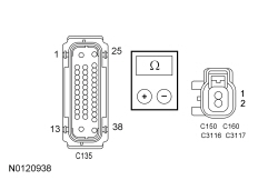
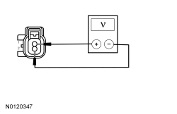
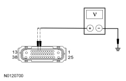
Pinpoint Test D: DTCs C0031:13, C0031:17, C0031:23 (LF), C0034:13, C0034:17, C0034:23 (RF), C0037:13, C0037:17, C0037:23 (LR), C003A:13, C003A:17 and C003A:23 (RR)
The wheel speed sensors are active sensors and generate a square wave signal that is sent to the ABS module. When the ignition is turned to the RUN position, the ABS module carries out a self-test to determine if the sensors are functional. Voltage and ground are supplied to the front and rear wheel speed sensors from the ABS module along a pair of wires.
Wheel speed sensor DTCs automatically clear when a successful test drive is carried out. A successful test drive includes speeds above 32 km/h (20 mph) and at least one ABS stop.
| DTC Description | Fault Trigger Conditions |
|---|---|
| These DTCs set in continuous memory and on-demand when the ABS module detects that the wheel speed sensor circuit is open or has high resistance. |
| These DTCs set in continuous memory and on-demand when the ABS module detects that the wheel speed sensor circuit indicates higher voltage than expected. |
| These DTCs set in continuous memory and on-demand when the ABS module detects that the wheel speed sensor circuit is shorted to ground. |
NOTICE: Use the correct probe adapter(s) when making measurements. Failure to use the correct probe adapter(s) may damage the connector.
| Test Step | Result / Action to Take | |||||||||||||||||||||||||||||||||||||||
|---|---|---|---|---|---|---|---|---|---|---|---|---|---|---|---|---|---|---|---|---|---|---|---|---|---|---|---|---|---|---|---|---|---|---|---|---|---|---|---|---|
| D1 CHECK FOR FAULT REPEATABILITY | ||||||||||||||||||||||||||||||||||||||||
| Yes
If the Rotunda Active Wheel Speed Sensor Tester is available, GO to D2 . If the Rotunda Active Wheel Speed Sensor Tester is not available, GO to D4 . No INSPECT the wheel speed sensors and wheel speed sensor wiring. REPAIR or INSTALL new as necessary. REFER to Wheel Speed Sensor — Front or Wheel Speed Sensor — Rear in this section. If any other DTCs are retrieved, REFER to the ABS Module DTC Chart in this section. | |||||||||||||||||||||||||||||||||||||||
| D2 CHECK THE ABS MODULE OUTPUT USING THE ROTUNDA ACTIVE WHEEL SPEED SENSOR TESTER | ||||||||||||||||||||||||||||||||||||||||
| Yes
GO to D3 . No GO to D5 . | |||||||||||||||||||||||||||||||||||||||
| D3 CHECK THE WHEEL SPEED SENSOR OUTPUT WITH THE ROTUNDA ACTIVE WHEEL SPEED SENSOR TESTER | ||||||||||||||||||||||||||||||||||||||||
| Yes
The system is operating correctly at this time. The concern may have been caused by a loose or corroded connector. CLEAR the DTCs. REPEAT the self-test. No If the current overload LED is not illuminated and the sensor output LEDs do not illuminate or if the current overload LED is illuminated red, INSTALL a new wheel speed sensor. REFER to Wheel Speed Sensor — Front or Wheel Speed Sensor — Rear in this section. CLEAR the DTCs. REPEAT the self-test. If the current overload LED is not illuminated and the sensor output LEDs illuminate green, but do not flash, INSTALL a new wheel speed sensor. REFER to Wheel Speed Sensor — Front or Wheel Speed Sensor — Rear in this section. CLEAR the DTCs. REPEAT the self-test. | |||||||||||||||||||||||||||||||||||||||
| D4 CHECK THE WHEEL SPEED SENSOR CIRCUITS FOR A SHORT TO BATTERY VOLTAGE | ||||||||||||||||||||||||||||||||||||||||
 | Yes
REPAIR the affected circuit(s) for a short to voltage. CLEAR the DTCs. REPEAT the self-test. No GO to D5 . | |||||||||||||||||||||||||||||||||||||||
| D5 CHECK THE WHEEL SPEED SENSOR CIRCUITS FOR A SHORT TO GROUND | ||||||||||||||||||||||||||||||||||||||||
 | Yes
GO to D6 . No REPAIR the affected circuit(s) for a short to ground. CLEAR the DTCs. REPEAT the self-test. | |||||||||||||||||||||||||||||||||||||||
| D6 CHECK THE WHEEL SPEED CIRCUITS FOR AN OPEN | ||||||||||||||||||||||||||||||||||||||||
 | Yes
GO to D7 . No REPAIR the affected circuit(s) for an open circuit. CLEAR the DTCs. REPEAT the self-test. | |||||||||||||||||||||||||||||||||||||||
| D7 CHECK FOR SHORTED WHEEL SPEED SENSOR CIRCUITS | ||||||||||||||||||||||||||||||||||||||||
 | Yes
GO to D8 . No REPAIR the affected circuit(s). CLEAR the DTCs. REPEAT the self-test. | |||||||||||||||||||||||||||||||||||||||
| D8 CHECK FOR CORRECT ABS MODULE OUTPUT | ||||||||||||||||||||||||||||||||||||||||
 | Yes
REPLACE the suspect wheel speed sensor. REFER to Wheel Speed Sensor — Front or Wheel Speed Sensor — Rear in this section. CLEAR the DTCs. REPEAT the self-test. No GO to D9 . | |||||||||||||||||||||||||||||||||||||||
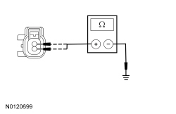
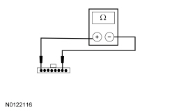
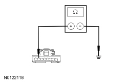
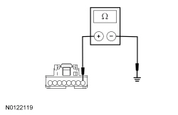
| D9 CHECK THE WHEEL SPEED SENSOR OUTPUT | ||||||||||||||||||||||||||||||||||||||||
NOTE: The digital multimeter must have the leads in the current sensing ports and the correct range selected. 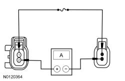 | Yes
GO to D10 . No INSTALL a new wheel speed sensor. REFER to Wheel Speed Sensor — Front or Wheel Speed Sensor — Rear in this section. CLEAR the DTCs. REPEAT the self-test. | |||||||||||||||||||||||||||||||||||||||
| D10 CHECK FOR CORRECT ABS MODULE OPERATION | ||||||||||||||||||||||||||||||||||||||||
| Yes
INSTALL a new ABS module. REFER to Anti-Lock Brake System (ABS) Module in this section. TEST the system for normal operation. No The system is operating correctly at this time. The concern may have been caused by a loose or corroded connector. CLEAR the DTCs. REPEAT the self-test. | |||||||||||||||||||||||||||||||||||||||
Pinpoint Test E: DTCs C0031:2F, C0031:62, C0034:2F, C0034:62, C0037:2F, C0037:62, C003A:2F, C003A:62 and C0078:61
The wheel speed sensors are active sensors and generate a square wave signal that is sent to the ABS module. When the ignition is turned to the RUN position, the ABS module carries out a self-test to determine if the sensors are functional. Voltage and ground are supplied to the front wheel speed sensors from the ABS module along 2 circuits.
Wheel speed sensor DTCs are set in continuous memory and they automatically clear when a successful test drive is carried out. A successful test drive includes speeds above 32 km/h (20 mph) and at least one ABS stop.
| DTC Description | Fault Trigger Conditions |
|---|---|
| These DTCs set in continuous memory when the vehicle speed exceeds 20 km/h (12 mph), and the ABS module detects an erratic wheel speed sensor acceleration. It can also be set by damaged tone rings, mismatched wheel and/or tire sizes or driving the vehicle on one or more deflated tires. |
| These DTCs set in continuous memory if the ABS module detects one of the wheel speed sensors has a missing signal or varies by 20% of the rest of the wheel speed sensors. There are no wheel speed sensor shorted or open circuit faults present in memory. |
| This DTC sets in continuous memory when the one wheel speed velocity differs from the rest by 25% or more. There are no wheel speed sensor faults set in memory. It can also be set by damaged tone rings, mismatched wheel and/or tire sizes or driving the vehicle on one or more deflated tires. |
NOTICE: Use the correct probe adapter(s) when making measurements. Failure to use the correct probe adapter(s) may damage the connector.
| Test Step | Result / Action to Take | |||||||||||||||
|---|---|---|---|---|---|---|---|---|---|---|---|---|---|---|---|---|
| E1 CHECK THE DTCs FROM THE SELF-TEST | ||||||||||||||||
| Yes
GO to Pinpoint Test D . No GO to E2 . | |||||||||||||||
| E2 CHECK THE TIRE SIZES AND PRESSURE | ||||||||||||||||
| Yes
GO to E3 . No INSTALL the correct size tire/wheel or ADJUST tire pressure as necessary. CLEAR the DTCs. REPEAT the self-test. | |||||||||||||||
| E3 MONITOR THE WHEEL SPEED SENSOR PIDs | ||||||||||||||||
| Yes
GO to E11 . No GO to E4 . | |||||||||||||||
| E4 CHECK THE WHEEL SPEED SENSOR FOR DAMAGE | ||||||||||||||||
| Yes
GO to E5 . No INSTALL a new wheel speed sensor. REFER to Wheel Speed Sensor — Front or Wheel Speed Sensor — Rear in this section. CLEAR the DTCs. REPEAT the self-test. | |||||||||||||||
| E5 INSPECT THE WHEEL SPEED SENSOR MOUNTING | ||||||||||||||||
| Yes
GO to E6 . No TIGHTEN the wheel speed sensor to specification. REFER to Specifications in this section. CLEAR the DTCs. REPEAT the self-test. | |||||||||||||||
| E6 CHECK TONE RING FOR DAMAGE | ||||||||||||||||
| Yes
For wheel speed sensor testing with the Rotunda Active Wheel Speed Sensor Tester, GO to E7 . For wheel speed sensor testing without the Rotunda Active Wheel Speed Sensor Tester, GO to E9 . No INSTALL a new tone ring as necessary. REFER to Wheel Speed Sensor Ring — Front or Wheel Speed Sensor Ring — Rear in this section. CLEAR the DTCs. REPEAT the self-test. | |||||||||||||||
| E7 CHECK THE ABS MODULE OUTPUT USING THE ROTUNDA ACTIVE WHEEL SPEED SENSOR TESTER | ||||||||||||||||
| Yes
GO to E8 . No GO to E11 . | |||||||||||||||
| E8 CHECK THE WHEEL SPEED SENSOR OUTPUT WITH THE ROTUNDA ACTIVE WHEEL SPEED SENSOR TESTER | ||||||||||||||||
| Yes
The system is operating correctly at this time. The concern may have been caused by a loose or corroded connector. CLEAR the DTCs. REPEAT the self-test. No If the current overload LED is not illuminated and the sensor output LEDs do not illuminate or if the current level LED is illuminated red, INSTALL a new wheel speed sensor. REFER to Wheel Speed Sensor — Front or Wheel Speed Sensor — Rear in this section. CLEAR the DTCs. REPEAT the self-test. If the current overload LED is not illuminated and the sensor output LEDs illuminate green, but do not flash, INSTALL a new wheel speed sensor. REFER to Wheel Speed Sensor — Front or Wheel Speed Sensor — Rear in this section. CLEAR the DTCs. REPEAT the self-test. If the sensor output LEDs still illuminate but do not flash REPLACE the suspect tone ring(s). REFER to Wheel Speed Sensor Ring — Front or Wheel Speed Sensor Ring — Rear in this section. | |||||||||||||||
| E9 CHECK FOR CORRECT ABS MODULE OUTPUT | ||||||||||||||||
| Yes
GO to E10 . No GO to E11 . | |||||||||||||||
| E10 CHECK THE WHEEL SPEED SENSOR OUTPUT | ||||||||||||||||
| Yes
GO to E11 . No INSTALL a new wheel speed sensor. REFER to Wheel Speed Sensor — Front or Wheel Speed Sensor — Rear in this section. CLEAR the DTCs. REPEAT the self-test. | |||||||||||||||
| E11 CHECK FOR CORRECT ABS MODULE OPERATION | ||||||||||||||||
| Yes
INSTALL a new ABS module. REFER to Anti-Lock Brake System (ABS) Module in this section. TEST the system for normal operation. No The system is operating correctly at this time. The concern may have been caused by a loose or corroded connector. CLEAR the DTCs. REPEAT the self-test. |
Pinpoint Test F: DTCs C0040:72 and C0040:73
The ABS module receives brake pedal input from the PCM over the High Speed Controller Area Network (HS-CAN). The ABS module compares this information against other inputs (wheel speed signals, vehicle speed signal, brake pressure transducer) to determine if the brake pedal input is valid.
NOTICE: Use the correct probe adapter(s) when making measurements. Failure to use the correct probe adapter(s) may damage the connector.
| Test Step | Result / Action to Take |
|---|---|
| F1 CHECK THE STOPLAMPS FOR CORRECT OPERATION | |
| Yes
GO to F2 . No REFER to Section 417-01 . |
| F2 CHECK THE ABS MODULE DTCs | |
| Yes
GO to Pinpoint Test I . No For DTC C0040:72 GO to F3 . For DTC C0040:73, INSTALL a new stoplamp switch. REFER to Section 417-01 . CLEAR the DTCs. REPEAT the self-test. |
| F3 CHECK THE ABS MODULE BRAKE PRESSURE PID | |
| Yes
The system is operating correctly at this time. CLEAR the DTCs. REPEAT the self-test. No GO to F4 . |
| F4 CHECK THE ABS MODULE BRAKE PRESSURE PID | |
| Yes
INSTALL a new cruise control deactivator switch. REFER to Section 419-03 . CLEAR the DTCs. REPEAT the self-test. No GO to F5 . |
| F5 CHECK THE ABS MODULE BRAKE PRESSURE PID | |
| Yes
INSTALL a new stoplamp switch. REFER to Section 417-01 . CLEAR the DTCs. REPEAT the self-test. No GO to F6 . |
| F6 CHECK FOR CORRECT ABS MODULE OPERATION | |
| Yes
INSTALL a new ABS module. REFER to Anti-Lock Brake System (ABS) Module in this section. TEST the system for normal operation. No The system is operating correctly at this time. The concern may have been caused by a loose or corroded connector. CLEAR the DTCs. REPEAT the self-test. |
Pinpoint Test G: DTC C1A98:54
Refer to Wiring Diagrams Cell 42 , Vehicle Dynamic Systems for schematic and connector information.
The ABS module needs to be calibrated whenever a component specific to the Electronic Stability Control (ESC) system is disconnected or a new component is installed. Calibration allows the ABS module to identify the zero position of the sensors so the system can operate correctly.
NOTE: The stability/traction control indicator (sliding car icon) flashes when a system calibration is required. Calibration is required after the ABS module or the Restraints Control Module (RCM) is replaced.
NOTE: The vehicle must be on level ground, at a complete standstill, in NEUTRAL with the brakes applied, and not on a hoist while carrying out the calibration procedure. Any vehicle movement results in calibration failure.
| Test Step | Result / Action to Take |
|---|---|
| G1 CHECK FOR ABS MODULE DTCs | |
| Yes
DIAGNOSE all other DTCs first. REFER to the ABS Module DTC Chart in this section. No GO to G2 . |
| G2 CALIBRATE THE ABS MODULE | |
| Yes
GO to G3 . No GO to G4 . |
| G3 CHECK FOR RETURNING DTCs | |
| Yes
The calibration is complete. The concern may have been caused by an incorrect or incomplete calibration. No GO to G4 . |
| G4 CHECK FOR CORRECT ABS MODULE OPERATION | |
| Yes
INSTALL a new ABS module. REFER to Anti-Lock Brake System (ABS) Module in this section. CLEAR the DTCs. REPEAT the self-test. No The system is operating correctly at this time. The concern may have been caused by a loose or corroded connector. CLEAR the DTCs. CARRY OUT the self-test with the brake pedal not applied. |
Pinpoint Test H: DTCs C1A99:14, C1A99:17, C1A99:2F, C1A99:62, C1A99:65 and C1A99:67
The ABS module uses internal pressure sensors to determine correct operation by monitoring internal Hydraulic Control Unit (HCU) hydraulic pressures. These DTCs set if the brake pressure sensor signals do not match. This fault could set by either an internal ABS module failure or an HCU pressure sensor failure. The pressure sensors are internal to the HCU and cannot be serviced separately.
| DTC Description | Fault Trigger Conditions |
|---|---|
| Sets in continuous memory if the brake pressure sensor signal is lower than expected. |
| Sets in continuous memory if the brake pressure sensor signal is higher than expected. |
| Sets in continuous memory if the brake pressure sensor signal is erratic or fluctuating abnormally. This fault could set by either an internal ABS module failure or a pressure sensor failure. |
| Sets in continuous memory if the brake pressure sensor signal fails the internal accuracy check. |
| Sets in continuous memory if the brake pressure sensor signals are not active. |
| Sets in continuous memory if the master cylinder pressure exceeds the allowed limit after an ABS event. |
| Test Step | Result / Action to Take |
|---|---|
| H1 CHECK THE BRAKE PEDAL AND BRACKET | |
| Yes
GO to H2 . No REPAIR or INSTALL new components as necessary. REFER to Section 206-06 . |
| H2 CHECK FOR DTCs C1A99:14, C1A99:17, C1A99:2F, C1A99:62, C1A99:65, C1A99:67 TO RETURN | |
| Yes
GO to H3 . No The system is operating correctly at this time. The concern may have been caused by air trapped in the hydraulic brake system. CLEAR the DTCs. REPEAT the self-test. |
| H3 CHECK FOR CORRECT ABS MODULE HCU TORQUE VALUES | |
| Yes
INSTALL a new ABS module. REFER to Anti-Lock Brake System (ABS) Module in this section. TEST the system for normal operation. No TIGHTEN all ABS module-to- HCU fasteners. REFER to Hydraulic Control Unit (HCU) in this section. CLEAR the DTCs. REPEAT the self-test. |
Pinpoint Test I: DTC U0100:00
Refer to Wiring Diagrams Cell 42 , Vehicle Dynamic Systems for schematic and connector information.
| Test Step | Result / Action to Take |
|---|---|
| I1 VERIFY THE SCAN TOOL COMMUNICATES WITH THE PCM | |
| Yes
GO to I2 . No REFER to Section 418-00 to diagnose no communication with the PCM. |
| I2 CHECK THE ABS MODULE CMDTCs | |
| Yes
GO to I3 . No The system is operating correctly at this time. The DTC may have been set due to high network traffic or an intermittent fault condition. |
| I3 RETRIEVE THE RECORDED DTCs FROM THE PCM KOEO SELF-TEST | |
| Yes
REFER to Section 303-14 . No GO to I4 . |
| I4 RETRIEVE THE RECORDED DTCs FROM THE ABS MODULE SELF-TEST | |
| Yes
For DTC B11E8:16, GO to Pinpoint Test A . For DTC B11E8:17, GO to Pinpoint Test B . No GO to I5 . |
| I5 CHECK FOR DTC U0100:00 SET IN OTHER MODULES | |
| Yes
INSTALL a new PCM. REFER to Section 303-14 . TEST the system for normal operation. No INSTALL a new ABS module. REFER to Anti-Lock Brake System (ABS) Module in this section. TEST the system for normal operation. |
Pinpoint Test J: DTC U0131:00
| Test Step | Result / Action to Take |
|---|---|
| J1 VERIFY THE CUSTOMER CONCERN | |
| Yes
GO to J2 . No The system is operating normally at this time. The DTC may have been set due to high network traffic or an intermittent fault condition. |
| J2 CHECK THE COMMUNICATION NETWORK | |
| Yes
GO to J3 . No REFER to Section 418-00 . |
| J3 RETRIEVE THE RECORDED DTCs FROM THE ABS MODULE AND PSCM SELF-TESTS | |
| Yes
For DTC B11E8:16, GO to Pinpoint Test A . For DTC B11E8:17, GO to Pinpoint Test B . For the PSCM , REFER to Section 211-00 . No GO to J4 . |
| J4 RECHECK THE ABS MODULE DTCs | |
| Yes
GO to J5 . No The system is operating correctly at this time. The DTC may have been set due to high network traffic or an intermittent fault condition. |
| J5 CHECK FOR DTC U0131:87 SET IN THE IPC | |
| Yes
INSTALL a new PSCM . REFER to Section 211-00 . CLEAR the DTCs. REPEAT the ABS module self-test. No INSTALL a new ABS module. REFER to Anti-Lock Brake System (ABS) Module in this section. TEST the system for normal operation. |
Pinpoint Test K: DTC U0151:00
Refer to Wiring Diagrams Cell 42 , Vehicle Dynamic Systems for schematic and connector information.
| Test Step | Result / Action to Take |
|---|---|
| K1 VERIFY THE CUSTOMER CONCERN | |
| Yes
GO to K2 . No The system is operating normally at this time. The DTC may have been set due to high network traffic or an intermittent fault condition. |
| K2 CHECK THE COMMUNICATION NETWORK | |
| Yes
GO to K3 . No REFER to Section 418-00 . |
| K3 RETRIEVE THE RECORDED DTCs FROM THE ABS MODULE AND RCM MODULE SELF-TESTS | |
| Yes
For DTC B11E8:16, GO to Pinpoint Test A . For DTC B11E8:17, GO to Pinpoint Test B . For the RCM , REFER to Section 501-20B . No GO to K4 . |
| K4 RECHECK THE ABS MODULE DTCs | |
| Yes
GO to K5 . No The system is operating correctly at this time. The DTC may have been set due to high network traffic or an intermittent fault condition. |
| K5 CHECK FOR DTC U0151:00 SET IN OTHER MODULES | |
| Yes
INSTALL a new RCM . REFER to Section 501-20B . CLEAR the DTCs. REPEAT the ABS module self-test. No INSTALL a new ABS module. REFER to Anti-Lock Brake System (ABS) Module in this section. TEST the system for normal operation. |
Pinpoint Test L: DTC U0155:00
Refer to Wiring Diagrams Cell 42 , Vehicle Dynamic Systems for schematic and connector information.
| Test Step | Result / Action to Take |
|---|---|
| L1 VERIFY THE CUSTOMER CONCERN | |
| Yes
GO to L2 . No The system is operating normally at this time. The DTC may have been set due to high network traffic or an intermittent fault condition. |
| L2 CHECK THE COMMUNICATION NETWORK | |
| Yes
GO to L3 . No REFER to Section 418-00 . |
| L3 RETRIEVE THE RECORDED DTCs FROM THE ABS MODULE AND IPC SELF-TESTS | |
| Yes
For DTC B11E8:16, GO to Pinpoint Test A . For DTC B11E8:17, GO to Pinpoint Test B . For the IPC , REFER to Section 413-01 . No GO to L4 . |
| L4 RECHECK THE ABS MODULE DTCs | |
| Yes
GO to L5 . No The system is operating correctly at this time. The DTC may have been set due to high network traffic or an intermittent fault condition. |
| L5 CHECK FOR DTC U0155:00 SET IN OTHER MODULES | |
| Yes
INSTALL a new IPC . REFER to Section 413-01 . CLEAR the DTCs. REPEAT the ABS module self-test. No INSTALL a new ABS module. REFER to Anti-Lock Brake System (ABS) Module in this section. TEST the system for normal operation. |
Pinpoint Test M: DTCs U1A00:49 and U1A00:87
The Restraints Control Module (RCM) measures vehicle yaw rate and lateral acceleration and sends the information to the ABS module along a dedicated Controller Area Network (CAN). This dedicated CAN is used only for communication between the RCM and the ABS module. The yaw rate sensor lateral accelerometer are contained in the RCM .
 WARNING: Never probe the electrical connectors on airbag, Safety Canopy or side air curtain assemblies. Failure to follow this instruction may result in the accidental deployment of these assemblies, which increases the risk of serious personal injury or death.
NOTICE: Use the correct probe adapter(s) when making measurements. Failure to use the correct probe adapter(s) may damage the connector.
| Test Step | Result / Action to Take | |||||||||
|---|---|---|---|---|---|---|---|---|---|---|
| M1 CHECK FOR AN HS-CAN CONCERN WITH THE RCM | ||||||||||
| Yes
GO to M2 . No REFER to Section 418-00 to diagnose the RCM does not respond to the scan tool. | |||||||||
| M2 VERIFY THE RCM PART NUMBER | ||||||||||
| Yes
GO to M3 . No INSTALL the correct RCM . REFER to Section 501-20B . CLEAR the DTCs. REPEAT the self-test. | |||||||||
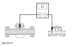
| M3 CHECK THE DEDICATED CAN CIRCUITS FOR A SHORT TO VOLTAGE | ||||||||||
 | Yes
REPAIR the affected circuit(s) for a short to voltage. CLEAR the DTCs. REPEAT the self-test. No GO to M4 . | |||||||||
| M4 CHECK THE DEDICATED CAN CIRCUITS FOR A SHORT TO GROUND | ||||||||||
 | Yes
GO to M5 . No REPAIR the affected circuit(s). TEST the system for normal operation. | |||||||||
| M5 CHECK THE DEDICATED CAN CIRCUITS FOR A SHORT TOGETHER | ||||||||||
 | Yes
GO to M6 . No REPAIR the circuits. CLEAR the DTCs. REPEAT the self-test. | |||||||||
| M6 CHECK THE DEDICATED CAN CIRCUITS FOR AN OPEN | ||||||||||
 | Yes
GO to M7 . No REPAIR the affected circuit(s). CLEAR the DTCs. CYCLE the ignition key. REPEAT the self-test. | |||||||||
| M7 CHECK FOR CORRECT RCM OPERATION | ||||||||||
| Yes
INSTALL a new RCM . REFER to Section 501-20B . CLEAR the DTCs. REPEAT the self-test. If DTCs U1A00:49 and U1A00:87 are retrieved again, GO to M8 . No The system is operating correctly at this time. The concern may have been caused by a loose or corroded connector. CLEAR the DTCs. REPEAT the self-test. | |||||||||
| M8 CHECK FOR CORRECT ABS MODULE OPERATION | ||||||||||
| Yes
INSTALL a new ABS module. REFER to Anti-Lock Brake System (ABS) Module in this section. TEST the system for normal operation. No The system is operating correctly at this time. The concern may have been caused by a loose or corroded connector. CLEAR the DTCs. REPEAT the self-test. |
Pinpoint Test N: DTC U3002:62
Refer to Wiring Diagrams Cell 42 , Vehicle Dynamic Systems for schematic and connector information.
When the ignition is turned to the RUN position, the ABS module and the PCM share Vehicle Identification Number (VIN) information over the High Speed Controller Area Network (HS-CAN).
| Test Step | Result / Action to Take |
|---|---|
| N1 VERIFY PCM VIN | |
| Yes
GO to N2 . No CARRY OUT Programmable Module Installation (PMI) for the PCM. REFER to Section 418-01 , using the Integrated Diagnostic System (IDS) when the original module is NOT available. TEST the system for normal operation. |
| N2 VERIFY ABS MODULE PART NUMBER | |
| Yes
CARRY OUT PMI for the ABS module. REFER to Section 418-01 , using the IDS when the original module is NOT available. TEST the system for normal operation. No INSTALL a new ABS module. REFER to Anti-Lock Brake System (ABS) Module in this section. CLEAR the DTC. CYCLE the ignition key. REPEAT the self-test. |
Pinpoint Test O: THE TRACTION CONTROL SYSTEM CANNOT BE DISABLED
Refer to Wiring Diagrams Cell 42 , Vehicle Dynamic Systems for schematic and connector information.
The traction control switch (part of the hazard flasher lamp switch) can be used by the driver to disable and enable the traction control systems. When the ignition is turned to the RUN position the stability/traction control OFF indicator (sliding car OFF icon) in the Instrument Panel Cluster (IPC) illuminates momentarily as a test. Momentarily pressing the switch disables the traction control system. When the traction control system is disabled through the use of the switch, the sliding car OFF icon illuminates continuously. The conventional ABS system cannot be disabled through the use of the stability/traction control switch. If a MyKey® restricted key is in use with the AdvanceTrac® always-on feature configured to on, the traction control system cannot be disabled. Only an admin key can be used to change a MyKey® traction control system setting from always-on to user select.
NOTICE: Use the correct probe adapter(s) when making measurements. Failure to use the correct probe adapter(s) may damage the connector.
| Test Step | Result / Action to Take |
|---|---|
| O1 CHECK FOR COMMUNICATION DTCs | |
| Yes
GO to Pinpoint Test L . No GO to O2 . |
| O2 CHECK THE STABILITY TRACTION CONTROL SWITCH STAB_CTRL_SW PID | |
| Yes
The system is operating correctly at this time. No GO to O3 . |
| O3 CHECK THE STABILITY TRACTION CONTROL SWITCH | |
 | Yes
GO to O4 . No INSTALL a new hazard flasher lamp switch. REFER to Section 417-01 . TEST the system for normal operation. |
| O4 CHECK STABILITY/TRACTION CONTROL CIRCUIT FOR AN OPEN | |
 | Yes
GO to O5 . No REPAIR circuit CCA15 (YE/GY) for an open. TEST the system for normal operation. |
| O5 CHECK STABILITY/TRACTION CONTROL CIRCUIT FOR A SHORT TO GROUND | |
 | Yes
GO to O6 . No REPAIR circuit CCA15 (YE/GY) for a short to ground. TEST the system for normal operation. |
| O6 CHECK GROUND CIRCUIT FOR AN OPEN | |
 | Yes
GO to O7 . No REPAIR circuit GD116 (BK/VT) for an open. TEST the system for normal operation. |
| O7 CHECK THE IPC CONNECTOR | |
| Yes
INSTALL a new IPC . REFER to Section 413-01 . TEST the system for normal operation. No The system is operating correctly at this time. Concern may have been caused by a loose or corroded connector. |