
NUD105-R025D or equivalent

FLU77-4 or equivalent

SECTION 414-00: Charging System
| 2014 Mustang Workshop Manual
|
DIAGNOSIS AND TESTING
| Procedure revision date: 01/07/2013
|
| Flex Probe Kit
NUD105-R025D or equivalent |
| Fluke 77-IV Digital Multimeter
FLU77-4 or equivalent |
| Vehicle Communication Module (VCM) and Integrated Diagnostic System (IDS) software with appropriate hardware, or equivalent scan tool
|
Pinpoint Test A: DTCs B1317, B1676 and/or P0563
Refer to Wiring Diagrams Cell 12 , Charging System for schematic and connector information.
NOTE: DTC B1317 or B1676 can be set if the vehicle has been recently jump started, the battery has been recently charged or the battery has been discharged. The battery may become discharged due to excessive load(s) on the charging system from aftermarket accessories or if vehicle accessories have been operating for an extended period of time without the engine running.
With the engine running, the charging system supplies voltage to the battery and the vehicle electrical system through the battery B+ cable. The voltage that is supplied to the vehicle electrical system is used for the operation of the various vehicle systems and modules. Many modules monitor this voltage and if it rises above a calibrated set point, this DTC sets.
NOTE: Make sure battery voltage is greater than 12.2 volts prior to and during this pinpoint test.
NOTE: Do not have a battery charger attached during vehicle testing.
| Test Step | Result / Action to Take |
|---|---|
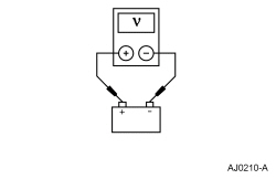
| A1 CHECK BATTERY CONDITION | |
| Yes
GO to A2 . No INSTALL a new battery. REFER to Section 414-01 . CLEAR the DTCs. REPEAT the self-test. TEST the system for normal operation. |
| A2 RETRIEVE PCM DTCs | |
| Yes
REFER to the DTC Chart for the correct pinpoint test and DIAGNOSE those DTCs first. No GO to A3 . |
| A3 MONITOR PCM PID GENERATOR VOLTAGE DESIRED (GENVDSD) | |
| Yes
GO to A4 . No GO to A11 . |
| A4 MONITOR PCM PID GENERATOR VOLTAGE DESIRED (GENVDSD) | |
 | Yes
The fault is not present at this time. This may indicate an intermittent fault. CARRY OUT a Wiggle Test on the charging system circuits to try and RECREATE the concern. CHECK generator connections for corrosion, loose connections and/or bent terminals. REPAIR as necessary. CLEAR the DTCs. REPEAT the self-test. TEST the system for normal operation. No GO to A5 . |
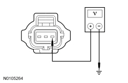
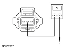
| A5 CHECK THE A SENSE VOLTAGE | |
 | Yes
GO to A6 . No VERIFYBattery Junction Box (BJB) fuse 17 (10A) is OK. If OK, REPAIR corroded or loose connections at the battery positive C1100C ,Battery Junction Box (BJB) C1035A, generator C102A and circuits SDC02 (RD) or SBB17 (RD). If not OK, REFER to the Wiring Diagrams manual to identify the possible causes of the circuit short. CLEAR the DTCs. REPEAT the self-test. TEST the system for normal operation. |
| A6 A SENSE CIRCUIT LOAD TEST | |
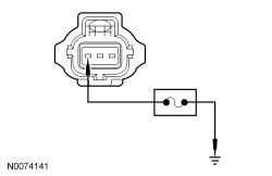
NOTICE: The following step uses a test light to simulate normal circuit loads. Use only the test light recommended in the Special Tools table at the beginning of this section. To avoid connector terminal damage, use the Flex Probe Kit for the test light probe connection to the vehicle. Do not use the test light probe directly on any connector. NOTE: This step puts a load on the A sense circuit. If there are corroded or loose connections, loading the circuit may help show the fault. A 250-350 mA incandescent 12-volt test lamp is required for this step. This circuit will not be loaded properly using an LED-style test lamp. 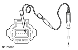 | Yes
GO to A7 . No REPAIR corroded or loose connections at the battery positive C1100C ,Battery Junction Box (BJB) C1035A, generator C102A and circuits SDC02 (RD) or SBB17 (RD). CLEAR the DTCs. REPEAT the self-test. TEST the system for normal operation. |
| A7 CHECK THE GENERATOR OUTPUT | |
| Yes
INSTALL a new generator. Refer to Generator — 3.7L , Generator — 5.0L or Generator — 5.8L (4V) . CLEAR the DTCs. REPEAT the self-test. TEST the system for normal operation. No GO to A8 . |
| A8 MONITOR PCM PIDs GENERATOR COMMAND (GENCMD), GENERATOR MONITOR (GENMON) AND GENERATOR VOLTAGE DESIRED (GENVDSD) | |
 | Yes
GO to A9 . No GO to A11 . |
| A9 COMPARE PCM MODULE SUPPLY VOLTAGE (VPWR) PID TO BATTERY VOLTAGE | |
| Yes
INSTALL a new generator. Refer to Generator — 3.7L , Generator — 5.0L or Generator — 5.8L (4V) . CLEAR the DTCs. REPEAT the self-test. TEST the system for normal operation. No GO to A10 . |
| A10 CHECK PCM SUPPLY VOLTAGE CIRCUITS | |
 | Yes
GO to A11 . No REPAIR high resistance or loose connections in the affected circuit(s). CLEAR the DTCs. REPEAT the self-test. TEST the system for normal operation. |
| A11 CHECK FOR CORRECT PCM OPERATION | |
| Yes
INSTALL a new PCM. REFER to Section 303-14 . CLEAR the DTCs. REPEAT the self-test. TEST the system for normal operation. No The system is operating correctly at this time. The concern may have been caused by a loose or corroded connector. CLEAR the DTCs. REPEAT the self-test. |
Pinpoint Test B: DTC P0532, B1318 and/or B1676
Refer to Wiring Diagrams Cell 12 , Charging System for schematic and connector information.
NOTE: DTCs B1318 or B1676 can be set if the vehicle has been recently jump started, the battery has been recently charged or the battery has been discharged. The battery may become discharged due to excessive load(s) on the charging system from aftermarket accessories or if vehicle accessories have been operating for an extended period of time without the engine running.
With the engine running, the charging system supplies voltage to the battery and the vehicle electrical system through the battery B+ cable. The voltage that is supplied to the vehicle electrical system is used for the operation of the vehicle and the various modules. Many modules monitor this voltage and if it drops below a calibrated set point, a DTC will be set.
NOTE: Make sure battery voltage is greater than 12.2 volts prior to and during this pinpoint test.
NOTE: Do not have a battery charger attached during vehicle testing.
| Test Step | Result / Action to Take |
|---|---|
| B1 CHECK THE BATTERY CONDITION | |
| Yes
GO to B2 . No INSTALL a new battery. REFER to Section 414-01 . CLEAR the DTCs. REPEAT the self-test. TEST the system for normal operation. |
| B2 CHECK THE VOLTAGE DROP IN THE VEHICLE GROUNDS | |
 | Yes
GO to B3 . No INSPECT for and REPAIR any corrosion or looseness in the engine ground, generator ground or the battery ground. CLEAR the DTCs. REPEAT the self-test. TEST the system for normal operation. |
| B3 CHECK THE VOLTAGE DROP IN THE GENERATOR B+ CIRCUIT | |
 | Yes
GO to B4 . No VERIFY the High Current Battery Junction Box (BJB) 200A fuse is OK. If OK, INSPECT for and REPAIR any corrosion or looseness in circuit SBF01 (RD), High-Current Battery Junction Box (BJB) C1617A, generator B+ C102B or C102C and positive battery cable connections. CLEAR the DTCs. REPEAT the self-test. TEST the system for normal operation. If fuse is not OK, INSPECT and REPAIR the cause of the circuit short before replacing the High Current Battery Junction Box (BJB). |
| B4 CHECK FOR CURRENT DRAINS | |
| Yes
REPAIR as necessary. CLEAR the DTCs. REPEAT the self-test. TEST the system for normal operation. No For 3.7L manual transmission , CARRY OUT the Generator Clutch component test in this section. If the generator clutch tests OK, CHECK with the customer to determine if any electrical system(s) may have been accidently left on. If nothing unusual is found, CLEAR the DTCs. REPEAT the self-test. TEST the system for normal operation. GO to Pinpoint Test D to continue diagnosis of the charging system. For all others , no problems found at this time. CHECK with the customer to determine if any electrical system(s) may have been accidently left on. If nothing unusual is found, CLEAR the DTCs. REPEAT the self-test. TEST the system for normal operation. GO to Pinpoint Test D to continue diagnosis of the charging system. |
Pinpoint Test C: DTC P0620
Refer to Wiring Diagrams Cell 12 , Charging System for schematic and connector information.
The PCM monitors the generator output via the GENMON circuit. The PCM uses the GENCOM circuit to command the generator to either increase or decrease output. If the GENCOM circuit (generator control circuit) or the A sense circuit is open or shorted to ground, the PCM will be unable to control the generators output. When the engine rises above approximately 2,000 rpm, the generator defaults to a steady voltage of approximately 13.5 volts and the PCM sends a request to the Instrument Cluster (IC) to illuminate the charging system warning indicator.
NOTE: Make sure battery voltage is greater than 12.2 volts prior to and during this pinpoint test.
NOTE: Do not have a battery charger attached during vehicle testing.
| Test Step | Result / Action to Take |
|---|---|
| C1 CHECK THE BATTERY CONDITION | |
| Yes
GO to C2 . No INSTALL a new battery. REFER to Section 414-01 . CLEAR the DTCs. REPEAT the self-test. TEST the system for normal operation. |
| C2 CHECK THE GENERATOR B+ CONNECTION | |
 | Yes
GO to C3 . No VERIFY the High Current Battery Junction Box (BJB) 200A fuse is OK. If OK, INSPECT for and REPAIR any corrosion or looseness in circuit SBF01 (RD), High-Current Battery Junction Box (BJB) C1617A, generator B+ C102B or C102C and positive battery cable connections. CLEAR the DTCs. REPEAT the self-test. TEST the system for normal operation. If fuse is not OK, INSPECT and REPAIR the cause of the circuit short before replacing the High Current Battery Junction Box (BJB). |
| C3 CHECK THE VOLTAGE DROP IN THE B+ CIRCUIT | |
| Yes
GO to C4 . No INSPECT for and REPAIR any corrosion in the B+ circuit SBF01 (RD), High Current Battery Junction Box (BJB) C1617A, generator B+ C102B or C102C and positive battery cable connections. CLEAR the DTCs. REPEAT the self-test. TEST the system for normal operation. |
| C4 A SENSE CIRCUIT LOAD TEST | |
NOTICE: The following step uses a test light to simulate normal circuit loads. Use only the test light recommended in the Special Tools table at the beginning of this section. To avoid connector terminal damage, use the Flex Probe Kit for the test light probe connection to the vehicle. Do not use the test light probe directly on any connector. NOTE: This step puts a load on the A sense circuit. If there are corroded or loose connections, loading the circuit may help show the fault. A 250-350 mA incandescent 12-volt test lamp is required for this step. This circuit will not be loaded properly using an LED-style test lamp. | Yes
GO to C5 . No VERIFY BJB fuse 17 (10A) is OK. If OK, REPAIR circuit SBB17 (RD). If not OK, REFER to the Wiring Diagrams Manual to identify the possible causes of the circuit short. CLEAR the DTCs. REPEAT the self-test. TEST the system for normal operation. |
| C5 CHECK THE GENERATOR COMMAND LINE FAULT (GENCMD_LF) PID | |
| Yes
GO to C6 . No GO to C9 . |
| C6 CHECK THE GENERATOR COMMAND CIRCUIT FOR A SHORT TO VOLTAGE | |
 | Yes
GO to C7 . No GO to C11 . |
| C7 COMPARE THE PCM PIDs GENERATOR MONITOR (GENMON) AND GENERATOR COMMAND (GENCMD) | |
| Yes
GO to C8 . No GO to C12 . |
| C8 CHECK THE GENERATOR COMMAND CIRCUIT FOR DAMAGE OR AN OPEN | |
 | Yes
GO to C9 . No REPAIR circuit CDC10 (BU/OG). CLEAR the DTCs. REPEAT the self-test. TEST the system for normal operation. |
| C9 CHECK THE GENERATOR COMMAND CIRCUIT FOR A SHORT TO GROUND | |
 | Yes
GO to C10 . No REPAIR the circuit. CLEAR the DTCs. REPEAT the self-test. TEST the system for normal operation. |
| C10 CHECK THE CHARGING SYSTEM CIRCUITS FOR INTERMITTENT FAULTS | |
| Yes
INSTALL a new generator. Refer to Generator — 3.7L , Generator — 5.0L or Generator — 5.8L (4V) . CLEAR the DTCs. REPEAT the self-test. TEST the system for normal operation. No The fault is not present at this time. This may indicate an intermittent fault. CARRY OUT a Wiggle Test on the charging system circuits to try and RECREATE the concern. CHECK generator connections for corrosion, loose connections and/or bent terminals. REPAIR as necessary. CLEAR the DTCs. REPEAT the self-test. TEST the system for normal operation. |
| C11 CHECK THE GENERATOR COMMAND CIRCUIT AND PCM FOR A SHORT TO VOLTAGE | |
| Yes
REPAIR circuit CDC10 (BU/OG). CLEAR the DTCs. REPEAT the self-test. TEST the system for normal operation. No INSTALL a new PCM. REFER to Section 303-14 . CLEAR the DTCs. REPEAT the self-test. TEST the system for normal operation. |
| C12 INSPECT GENERATOR CIRCUITS | |
| Yes
INSTALL a new PCM. REFER to Section 303-14 . CLEAR the DTCs. REPEAT the self-test. TEST the system for normal operation. No REPAIR high resistance or loose connections in the affected circuit(s). CLEAR the DTCs. REPEAT the self-test. TEST the system for normal operation. |
Pinpoint Test D: DTCs P0625 and P0626
Refer to Wiring Diagrams Cell 12 , Charging System for schematic and connector information.
The PCM monitors the generator output via the GENMON circuit (generator field terminal circuit). If the PCM cannot read the GENMON circuit due to an open or short to ground, when the engine rises above approximately 2,000 rpm, the generator defaults to a steady voltage of approximately 13.5 volts and the PCM sends a request to the Instrument Cluster (IC) to illuminate the charging system warning indicator.
NOTE: Make sure battery voltage is greater than 12.2 volts prior to and during this pinpoint test.
NOTE: Do not have a battery charger attached during vehicle testing.
| Test Step | Result / Action to Take | ||||||||
|---|---|---|---|---|---|---|---|---|---|
| D1 CHECK THE BATTERY CONDITION | |||||||||
| Yes
GO to D2 . No INSTALL a new battery. REFER to Section 414-01 . CLEAR the DTCs. REPEAT the self-test. TEST the system for normal operation. | ||||||||
| D2 CHECK THE HIGH CURRENT BATTERY JUNCTION BOX AND GENERATOR B+ CONNECTION | |||||||||
| Yes
GO to D3 . No VERIFY the high current BJB 200A fuse is OK. If OK, INSPECT and REPAIR any corrosion or looseness in circuit SBF01 (RD), high current BJB C1617A, generator B+ C102B or C102C and positive battery cable connections. CLEAR the DTCs. REPEAT the self-test. TEST the system for normal operation. If not OK, INSPECT and REPAIR the cause of the circuit short before replacing the high current BJB . | ||||||||
| D3 CHECK THE A SENSE VOLTAGE | |||||||||
| Yes
GO to D4 . No VERIFYBattery Junction Box (BJB) fuse 17 (10A) is OK. If OK, REPAIR corroded or loose connections at the battery positive C1100C ,Battery Junction Box (BJB) C1035A, generator C102A and circuits SDC02 (RD) or SBB17 (RD). If not OK, REFER to the Wiring Diagrams manual to identify the possible causes of the circuit short. CLEAR the DTCs. REPEAT the self-test. TEST the system for normal operation. | ||||||||
| D4 MONITOR THE PCM PID GENERATOR MONITOR (GENMON) | |||||||||
| Yes
GO to D5 . No GO to D10 . | ||||||||
| D5 MONITOR THE PCM PIDs GENERATOR MONITOR (GENMON) AND GENERATOR VOLTAGE DESIRED (GENVDSD) WITH THE ENGINE RUNNING AND NO LOADS | |||||||||
| Yes
GO to D6 . No GO to D11 . | ||||||||
| D6 MONITOR THE PCM PIDs GENERATOR MONITOR (GENMON), GENERATOR VOLTAGE DESIRED (GENVDSD) WITH THE ENGINE AT IDLE LOADS ON | |||||||||
| Yes
GO to D7 . No GO to D11 . | ||||||||
| D7 MONITOR THE PCM PIDs GENERATOR MONITOR (GENMON), MODULE SUPPLY VOLTAGE (VPWR) AND GENERATOR VOLTAGE DESIRED (GENVDSD) WITH THE ENGINE AT 3,000 RPM | |||||||||
| Yes
GO to D8 . No GO to D11 . | ||||||||
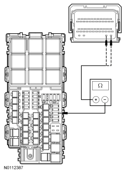
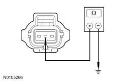
| D8 CHECK THE GENERATOR B+ RESISTANCE | |||||||||
 | Yes
GO to D9 . No INSTALL a new generator. Refer to Generator — 3.7L , Generator — 5.0L or Generator — 5.8L (4V) . CLEAR the DTCs. REPEAT the self-test. TEST the system for normal operation. | ||||||||
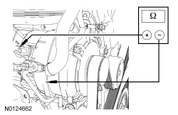
| D9 CHECK THE RESISTANCE OF THE VOLTAGE REGULATOR INTERNAL CIRCUITS TO GROUND | |||||||||
 | Yes
The fault is not present at this time. This may indicate an intermittent fault. CARRY OUT a Wiggle Test on the charging system circuits to try and RECREATE the concern. CHECK generator connections for corrosion, loose connections and/or bent terminals. REPAIR as necessary. CLEAR the DTCs. REPEAT the self-test. TEST the system for normal operation. No INSTALL a new generator. Refer to Generator — 3.7L , Generator — 5.0L or Generator — 5.8L (4V) . CLEAR the DTCs. REPEAT the self-test. TEST the system for normal operation. | ||||||||
| D10 CHECK THE PCM PID GENERATOR MONITOR (GENMON) INPUT TO THE PCM | |||||||||
 | Yes
GO to D14 . No GO to D15 . | ||||||||
| D11 A SENSE CIRCUIT LOAD TEST | |||||||||
NOTICE: The following step uses a test light to simulate normal circuit loads. Use only the test light recommended in the Special Tools table at the beginning of this section. To avoid connector terminal damage, use the Flex Probe Kit for the test light probe connection to the vehicle. Do not use the test light probe directly on any connector. NOTE: This step puts a load on the A sense circuit. If there are corroded or loose connections, loading the circuit may help show the fault. A 250-350 mA incandescent 12-volt test lamp is required for this step. This circuit will not be loaded properly using an LED-style test lamp. | Yes
GO to D12 . No VERIFYBattery Junction Box (BJB) fuse 17 (10A) is OK. If OK, REPAIR corroded or loose connections at the battery positive C1100C ,Battery Junction Box (BJB) C1035A, generator C102A or circuits SDC02 (RD) or SBB17 (RD). If not OK, REFER to the Wiring Diagrams manual to identify the possible causes of the circuit short. CLEAR the DTCs. REPEAT the self-test. TEST the system for normal operation. | ||||||||
| D12 B+ CIRCUIT LOAD TEST | |||||||||
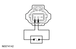
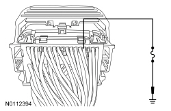
NOTE: This step puts a load on the B+ circuit. If there are corroded or loose connections, loading the circuit may help show the fault. A glass bulb style test lamp is required for this step. This circuit will not be loaded properly using an LED-style test lamp. 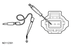 | Yes
GO to D13 . No REPAIR circuit CDC15 (VT) for high resistance. CLEAR the DTCs. REPEAT the self-test. TEST the system for normal operation. | ||||||||
| D13 CHECK THE GENERATOR COMMAND CIRCUIT FOR DAMAGE OR AN OPEN | |||||||||
| Yes
GO to D14 . No REPAIR circuit CDC10 (BU/OG). CLEAR the DTCs. REPEAT the self-test. TEST the system for normal operation. | ||||||||
| D14 COMPARE THE PCM PIDs GENERATOR MONITOR (GENMON) AND GENERATOR COMMAND (GENCMD) | |||||||||
| Yes
INSTALL a new generator. Refer to Generator — 3.7L , Generator — 5.0L or Generator — 5.8L (4V) . CLEAR the DTCs. REPEAT the self-test. TEST the system for normal operation. No GO to D16 . | ||||||||
| D15 INSPECT GENERATOR CIRCUITS | |||||||||
| Yes
INSTALL a new PCM. REFER to Section 303-14 . CLEAR the DTCs. REPEAT the self-test. TEST the system for normal operation. No REPAIR the affected circuit(s). CLEAR the DTCs. REPEAT the self-test. TEST the system for normal operation. | ||||||||
| D16 INSPECT PCM CIRCUITS | |||||||||
| Yes
INSTALL a new PCM. REFER to Section 303-14 . CLEAR the DTCs. REPEAT the self-test. TEST the system for normal operation. No REPAIR the affected circuit(s). CLEAR the DTCs. REPEAT the self-test. TEST the system for normal operation |
Pinpoint Test E: DTC P065B
Refer to Wiring Diagrams Cell 12 , Charging System for schematic and connector information.
The PCM monitors the generator output via the GENMON circuit. The signal that is monitored by the PCM on the GENMON circuit is a controlled frequency range. If the signal is outside of this prescribed range, the PCM is be unable to read the signal. When the engine rises above approximately 2,000 rpm, the generator defaults to a steady voltage of approximately 13.5 volts and the PCM sends a request to the Instrument Cluster (IC) to illuminate the charging system warning indicator lamp.
NOTE: Make sure battery voltage is greater than 12.2 volts prior to carrying out this pinpoint test.
NOTE: Do not have a battery charger attached during vehicle testing.
| Test Step | Result / Action to Take |
|---|---|
| E1 CHECK THE BATTERY CONDITION | |
| Yes
GO to E2 . No INSTALL a new battery. REFER to Section 414-01 . CLEAR the DTCs . REPEAT the self-test. TEST the system for normal operation. |
| E2 CHECK THE GENERATOR B+ CONNECTION | |
| Yes
GO to E3 . No VERIFY the High Current Battery Junction Box (BJB) 200A fuse is OK. If OK, INSPECT for and REPAIR any corrosion or looseness in circuit SBF01 (RD), High-Current Battery Junction Box (BJB) C1617A, generator B+ C102B or C102C and positive battery cable connections. CLEAR the DTCs. REPEAT the self-test. TEST the system for normal operation. If fuse is not OK, INSPECT and REPAIR the cause of the circuit short before replacing the High Current Battery Junction Box (BJB). |
| E3 A SENSE CIRCUIT LOAD TEST | |
NOTICE: The following step uses a test light to simulate normal circuit loads. Use only the test light recommended in the Special Tools table at the beginning of this section. To avoid connector terminal damage, use the Flex Probe Kit for the test light probe connection to the vehicle. Do not use the test light probe directly on any connector. NOTE: This step puts a load on the A sense circuit. If there are corroded or loose connections, loading the circuit may help show the fault. A 250-350 mA incandescent 12-volt test lamp is required for this step. This circuit will not be loaded properly using an LED-style test lamp. | Yes
GO to E4 . No VERIFY BJB fuse 17 (10A) is OK. If OK, REPAIR circuit SBB17 (RD). If not OK, REFER to the Wiring Diagrams Manual to identify the possible causes of the circuit short. CLEAR the DTCs. REPEAT the self-test. TEST the system for normal operation. |
| E4 CHECK THE GENERATOR MONITOR FREQUENCY (GENMON_HZ) PID | |
| Yes
GO to E8 . No GO to E5 . |
| E5 CHECK THE PCM GENERATOR MONITOR FREQUENCY (GENMON_HZ) PID WITH GENERATOR C102A DISCONNECTED | |
| Yes
GO to E7 . No GO to E6 . |
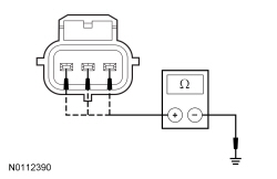
| E6 CHECK GENERATOR CIRCUITRY | |
 | Yes
INSPECT the harness for wire to wire shorts or insulation chaffing, mis-pinned connectors and correct wire colors and REPAIR generator circuit CDC15 (VT) as needed. CLEAR the DTCs. REPEAT the self-test. TEST the system for normal operation. No INSTALL a new PCM. REFER to Section 303-14 . CLEAR the DTCs. REPEAT the self-test. TEST the system for normal operation. |
| E7 MONITOR THE PCM PID GENERATOR MONITOR FREQUENCY (GENMON_HZ) WHILE ACTIVATING THE GENERATOR VOLTAGE DESIRED (GENVDSD) PID | |
| Yes
INSTALL a new generator. Refer to Generator — 3.7L , Generator — 5.0L or Generator — 5.8L (4V) . CLEAR the DTCs. REPEAT the self-test. TEST the system for normal operation. No INSTALL a new PCM. REFER to Section 303-14 . CLEAR the DTCs. REPEAT the self-test. TEST the system for normal operation. |
| E8 CHECK THE PCM GENERATOR COMMAND LINE FAULT (GENCMD_LF) PID | |
| Yes
INSTALL a new generator. Refer to Generator — 3.7L , Generator — 5.0L or Generator — 5.8L (4V) . CLEAR the DTCs. REPEAT the self-test. TEST the system for normal operation. No The fault is not present at this time. This may indicate an intermittent fault. CARRY OUT a wiggle test on the charging system circuits to try and RECREATE the concern. CHECK the generator and High Current BJB connections for corrosion, loose connections and/or bent terminals. REPAIR as necessary. CLEAR the DTCs. REPEAT the self-test. TEST the system for normal operation. |
Pinpoint Test F: The Generator is Noisy
Refer to Wiring Diagrams Cell 12 , Charging System for schematic and connector information.
The generator is belt-driven by the engine accessory drive system. There are 2 sources of generator noise: bearing noise and electrical fault noise. A generator with certain types of diode or stator failures may also produce an audible noise.
| Test Step | Result / Action to Take |
|---|---|
| F1 CHECK FOR ACCESSORY DRIVE BELT NOISE AND LOOSE MOUNTING BRACKETS | |
| Yes
GO to F2 . No REPAIR as necessary. REFER to Section 303-05 for diagnosis and testing of the accessory drive system. TEST the system for normal operation. |
| F2 CHECK THE GENERATOR MOUNTING | |
| Yes
GO to F3 . No REPAIR as necessary. TEST the system for normal operation. |
| F3 CHECK THE GENERATOR FOR MECHANICAL NOISE | |
| Yes
For 3.7L manual transmission , CARRY OUT the Generator Clutch component test in this section. If the generator clutch tests OK, INSTALL a new generator. REFER to Generator — 3.7L in this section. For all others , INSTALL a new generator. Refer to Generator — 3.7L , Generator — 5.0L or Generator — 5.8L (4V) . DTCs. No REFER to Section 303-00 to diagnose the source of the engine noise. |
Pinpoint Test G: Radio Interference
Refer to Wiring Diagrams Cell 12 , Charging System for schematic and connector information.
The generator radio suppression equipment reduces interference transmitted through the speakers by the vehicle electrical system.
NOTE: If the OEM audio unit has been replaced with an aftermarket unit, the vehicle may not pass this test. Return the vehicle to OEM condition before following this pinpoint test.
NOTE: If the engine is operated at greater than 2,000 rpm momentarily, the generator self-excites. Make sure when the generator is disconnected the engine rpm stays below 2,000 rpm. If it does rise above 2,000 rpm, turn the ignition to the off position and start the test over again.
NOTE: Inspect for any aftermarket accessories that have been added to the vehicle. Check the wiring for these accessories and be sure they have not been attached to the generator circuits and are positioned away from the generator wiring.
| Test Step | Result / Action to Take |
|---|---|
| G1 VERIFY THE GENERATOR IS THE SOURCE OF THE RADIO INTERFERENCE | |
| Yes
REFER to Section 415-00 for diagnosis and testing of the in-vehicle entertainment system. No INSTALL a new generator. Refer to Generator — 3.7L , Generator — 5.0L or Generator — 5.8L (4V) . TEST the system for normal operation. |
Component tests
Generator Clutch
NOTE: This procedure only applies to the 3.7L manual transmission.
Remove the generator. For additional information, refer to Generator — 3.7L in this section.