
FLU77-4 or equivalent


105-R025D or equivalent
SECTION 417-01: Exterior Lighting
| 2014 Mustang Workshop Manual
|
DIAGNOSIS AND TESTING
| Procedure revision date: 01/07/2013
|
| Fluke 77-IV Digital Multimeter
FLU77-4 or equivalent |
| Vehicle Communication Module (VCM) and Integrated Diagnostic System (IDS) software with appropriate hardware, or equivalent scan tool
|
| Flex Probe Kit
105-R025D or equivalent |
Principles of Operation
NOTE: The Smart Junction Box (SJB) is also known as the Generic Electronic Module (GEM).
The SJB monitors the headlamp switch position by sending a voltage signal to the headlamp switch. When the fog lamp switch (part of the headlamp switch) is engaged, the voltage reference signal is routed to ground.
The fog lamps can be turned on when the following conditions are met:
When the SJB receives an input from the headlamp switch indicating a request for the fog lamps, the SJB energizes the fog lamp relay (integrated into the SJB ). When the fog lamp relay is energized, voltage is routed to the fog lamps and the fog lamps on indicator (located within the headlamp switch). The GT fog lamps are equipped with an LED that is only serviced with the fog lamp assembly.
Inspection and Verification
Visual Inspection Chart
| Electrical |
|---|
|
NOTE: Make sure to use the latest scan tool software release.
If the cause is not visually evident, connect the scan tool to the Data Link Connector (DLC).NOTE: The Vehicle Communication Module (VCM) LED prove-out confirms power and ground from the DLC are provided to the VCM .
If the scan tool does not communicate with the VCM :Symptom Chart
| Condition | Possible Sources | Action |
|---|---|---|
|
| |
|
|
|
|
| |
|
|
Pinpoint Tests
Pinpoint Test S: Both Fog Lamps Are Inoperative
Refer to Wiring Diagrams Cell 86 , Fog Lamps for schematic and connector information.
The Smart Junction Box (SJB) sends a voltage signal to the headlamp switch to monitor the fog lamp request. When the fog lamp switch is engaged, the voltage signal is routed to ground.
When the SJB detects the fog lamps on request, the SJB energizes the fog lamp relay (integrated into the SJB ). When the fog lamp relay is energized, voltage is routed to the fog lamps.
This pinpoint test is intended to diagnose the following:
NOTICE: Use the correct probe adapter(s) when making measurements. Failure to use the correct probe adapter(s) may damage the connector.
| Test Step | Result / Action to Take |
|---|---|
| S1 CHECK THE SJB FOG LAMP SWITCH PID | |
| Yes
VERIFY the SJB fuse 21 (15A) is OK. If OK, GO to S4 . If not OK, REFER to the Wiring Diagrams Manual to identify the possible causes of the circuit short. No GO to S2 . |
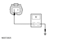
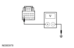
| S2 CHECK FOR VOLTAGE TO THE HEADLAMP SWITCH | |
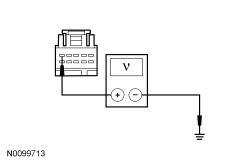 | Yes
INSTALL a new headlamp switch. REFER to Headlamp Switch in this section. TEST the system for normal operation. No GO to S3 . |
| S3 CHECK THE FOG LAMPS ON REQUEST INPUT CIRCUIT FOR AN OPEN | |
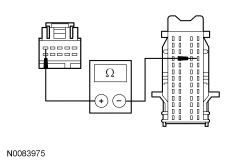 | Yes
GO to S5 . No REPAIR circuit CLF21 (GY/VT) for an open. TEST the system for normal operation. |
| S4 BYPASS THE SJB | |
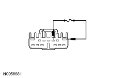 | Yes
REMOVE the jumper wire. GO to S6 . No LEAVE the jumper wire connected. GO to S5 . |
| S5 CHECK FOR VOLTAGE TO THE FOG LAMP | |
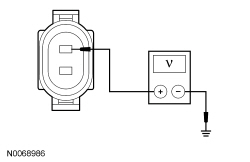 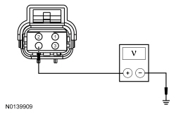  | Yes
REPAIR the ground circuit in question for an open. TEST the system for normal operation. No REPAIR circuit CLF12 (BN/YE) for an open. TEST the system for normal operation. |
| S6 CHECK FOR CORRECT SJB OPERATION | |
| Yes
INSTALL a new SJB . REFER to Section 419-10 . TEST the system for normal operation. No The system is operating correctly at this time. The concern may have been caused by a loose or corroded connector. |
Pinpoint Test T: An Individual Fog Lamp Is Inoperative
Refer to Wiring Diagrams Cell 86 , Fog Lamps for schematic and connector information.
When the SJB receives an input from the headlamp switch indicating a request for the fog lamps, the SJB energizes the fog lamp relay (integrated into the SJB ). When the fog lamp relay is energized, voltage is routed to the fog lamps and the fog lamps on indicator (located within the headlamp switch).
This pinpoint test is intended to diagnose the following:
NOTICE: Use the correct probe adapter(s) when making measurements. Failure to use the correct probe adapter(s) may damage the connector.
| Test Step | Result / Action to Take |
|---|---|
| T1 CHECK FOR VOLTAGE TO THE FOG LAMP | |
| Yes
For all except GT, REPAIR the ground circuit in question for an open. TEST the system for normal operation. For GT, GO to T2 . No REPAIR circuit CLF12 (BN/YE) for an open. TEST the system for normal operation. |
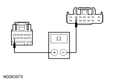
| T2 CHECK THE FOG LAMP GROUND CIRCUIT | |
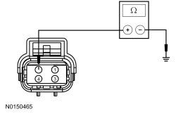 | Yes
INSTALL a new fog lamp assembly. Fog Lamp . No REPAIR the ground circuit in question for an open. TEST the system for normal operation. |
Pinpoint Test U: The Fog Lamps Are On Continuously
Refer to Wiring Diagrams Cell 86 , Fog Lamps for schematic and connector information.
The Smart Junction Box (SJB) sends a voltage signal to the headlamp switch to monitor the fog lamp request. When the fog lamp switch is engaged, the voltage signal is routed to ground.
When the SJB detects the fog lamps on request, the SJB energizes the fog lamp relay (integrated into the SJB ). When the fog lamp relay is energized, voltage is routed to the fog lamps, and on a separate output, to the headlamp switch for the fog lamps on indicator.
This pinpoint test is intended to diagnose the following:
NOTICE: Use the correct probe adapter(s) when making measurements. Failure to use the correct probe adapter(s) may damage the connector.
| Test Step | Result / Action to Take |
|---|---|
| U1 CHECK FOR RECORDED SJB DTCs | |
| Yes
GO to U2 . No GO to U4 . |
| U2 CHECK THE HEADLAMP SWITCH | |
| Yes
GO to U3 . No INSTALL a new headlamp switch. REFER to Headlamp Switch in this section. TEST the system for normal operation. |
| U3 CHECK THE FOG LAMPS ON REQUEST INPUT CIRCUIT FOR A SHORT TO GROUND | |
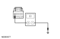 | Yes
GO to U6 . No REPAIR circuit CLF21 (GY/VT) for a short to ground. CLEAR the DTCs. REPEAT the self-test. |
| U4 CHECK THE SJB FOG LAMPS OUTPUT CIRCUIT FOR A SHORT TO VOLTAGE (TO HEADLAMP SWITCH) | |
| Yes
GO to U5 . No REPAIR circuit CLF12 (BN/YE) for a short to voltage. TEST the system for normal operation. |
| U5 CHECK THE SJB FOG LAMPS OUTPUT CIRCUIT FOR A SHORT TO VOLTAGE (TO THE FOG LAMPS) | |
| Yes
REPAIR circuit CLF12 (BN/YE) for a short to voltage. TEST the system for normal operation. No GO to U6 . |
| U6 CHECK FOR CORRECT SJB OPERATION | |
| Yes
INSTALL a new SJB . REFER to Section 419-10 . TEST the system for normal operation. No The system is operating correctly at this time. The concern may have been caused by a loose or corroded connector. CLEAR any DTCs. REPEAT the self-test. |
Pinpoint Test V: The Fog Lamps On Indicator Is Inoperative
Refer to Wiring Diagrams Cell 86 , Fog Lamps for schematic and connector information.
When the Smart Junction Box (SJB) detects the fog lamps on request, the SJB energizes the fog lamp relay (integrated into the SJB ). When the fog lamp relay is energized, voltage is routed to the fog lamps, and on a separate output, to the headlamp switch for the fog lamps on indicator.
This pinpoint test is intended to diagnose the following:
NOTICE: Use the correct probe adapter(s) when making measurements. Failure to use the correct probe adapter(s) may damage the connector.
| Test Step | Result / Action to Take |
|---|---|
| V1 CHECK THE HEADLAMP SWITCH | |
 | Yes
INSTALL a new headlamp switch. REFER to Headlamp Switch in this section. TEST the system for normal operation. No GO to V2 . |
| V2 CHECK THE SJB FOG LAMPS OUTPUT CIRCUIT FOR AN OPEN | |
 | Yes
GO to V3 . No REPAIR circuit CLF12 (BN/YE) for an open. CLEAR the DTCs. REPEAT the self-test. |
| V3 CHECK FOR CORRECT SJB OPERATION | |
| Yes
INSTALL a new SJB . REFER to Section 419-10 . TEST the system for normal operation. No The system is operating correctly at this time. The concern may have been caused by a loose or corroded connector. CLEAR any DTCs. REPEAT the self-test. |