
FLU77-4 or equivalent


105-R025D or equivalent
SECTION 417-01: Exterior Lighting
| 2014 Mustang Workshop Manual
|
DIAGNOSIS AND TESTING
| Procedure revision date: 01/07/2013
|
| Fluke 77-IV Digital Multimeter
FLU77-4 or equivalent |
| Vehicle Communication Module (VCM) and Integrated Diagnostic System (IDS) software with appropriate hardware, or equivalent scan tool
|
| Flex Probe Kit
105-R025D or equivalent |
Principles of Operation
NOTE: The Smart Junction Box (SJB) is also known as the Generic Electronic Module (GEM).
The SJB monitors the multifunction switch position by sending multiple voltage signals to the multifunction switch. When the multifunction switch is in the LH or RH TURN positions, or the hazard lamp switch is pressed, that input signal is routed to ground.
When the SJB receives a request for a turn signal or hazard lamps, the SJB supplies voltage to the front turn lamps and sends a message to the Body Control Module B (BCM-B) to flash (sequential or non-sequential) the rear lamps.
The timed on/off cycle is determined by the SJB and is set to flash approximately 80 times per minute if both the front and rear turn lamps operate correctly. If an individual turn signal lamp is determined inoperative by the SJB or the BCM-B , the SJB and the BCM-B (non-sequentially) flash the remaining turn lamp(s) approximately 160 times per minute.
The timed on/off cycle for the hazard lamps is set to flash approximately 80 times per minute.
The rear turn lamps are set to flash sequentially from the inboard lamp to the outboard lamp. The rear lamps do not flash sequentially for the hazard function.
Field-Effect Transistor (FET) Protection
Field-Effect Transistor (FET) is a type of transistor that when used with module software can be used to monitor and control current flow on module outputs. The FET protection strategy is used to prevent module damage in the event of excessive current flow.
The SJB utilizes a FET protective circuit strategy for many of its outputs (for example, a headlamp output circuit). Output loads (current level) are monitored for excessive current (typically short circuits) and are shut down (turns off the voltage or ground provided by the module) when a fault event is detected. A continuous DTC is stored at the fault event and a cumulative counter is started.
When the demand for the output is no longer present, the module resets the FET circuit protection to allow the circuit to function. The next time the driver requests a circuit to activate that has been shut down by a previous short ( FET protection) and the circuit remains shorted, the FET protection shuts off the circuit again and the cumulative counter advances.
When the excessive circuit load occurs often enough, the module shuts down the output until a repair procedure is carried out. Each FET protected circuit has 3 predefined levels of short circuit tolerance based on the harmful effect of each circuit fault on the FET and the ability of the FET to withstand it. A module lifetime level of fault events is established based upon the durability of the FET . If the total tolerance level is determined to be 600 fault events, the 3 predefined levels would be 200, 400 and 600 fault events.
When each tolerance level is reached, the continuous DTC that was stored on the first failure cannot be cleared by a command to clear the continuous DTCs. The module does not allow this code to be cleared or the circuit restored to normal operation until a successful self-test proves that the fault has been repaired. After the self-test has successfully completed (no on-demand DTCs present), DTC B106E and the associated continuous DTC (the DTC related to the shorted circuit) automatically clears and the circuit function returns.
When the first or second level is reached, the continuous DTC (associated with the short circuit) sets along with DTC B106E. These DTCs can be cleared using the module on-demand self-test, then the Clear DTC operation on the scan tool (if the on-demand test shows the fault corrected). The module never resets the fault event counter to zero and continues to advance the fault event counter as short circuit fault events occur.
If the number of short circuit fault events reach the third level, then DTCs B106F and B1342 set along with the associated continuous DTC. This DTC cannot be cleared and the module must be replaced.
The SJB FET protected circuits for the turn lamp system are the LH and RH front turn lamp output circuits.
Inspection and Verification
Visual Inspection Chart
| Mechanical | Electrical |
|---|---|
|
|
NOTE: Make sure to use the latest scan tool software release.
If the cause is not visually evident, connect the scan tool to the Data Link Connector (DLC).NOTE: The Vehicle Communication Module (VCM) LED prove-out confirms power and ground from the DLC are provided to the VCM .
If the scan tool does not communicate with the VCM :Symptom Chart
| Condition | Possible Sources | Action |
|---|---|---|
|
| |
|
| |
|
|
|
|
| |
|
|
Pinpoint Tests
Pinpoint Test L: The Turn Signal Lamps Are Inoperative
Refer to Wiring Diagrams Cell 90 , Turn Signal/Stop/Hazard Lamps for schematic and connector information.
The Smart Junction Box (SJB) sends voltage signals to the multifunction switch. When the multifunction switch is switched to the LH or RH TURN position, the voltage signal is routed to ground. When the SJB detects the multifunction switch is in the LH or RH TURN position, the SJB sends voltage to the appropriate front turn lamps.
This pinpoint test is intended to diagnose the following:
NOTICE: Use the correct probe adapter(s) when making measurements. Failure to use the correct probe adapter(s) may damage the connector.
| Test Step | Result / Action to Take |
|---|---|
| L1 CHECK FOR CORRECT HIGH BEAM OPERATION | |
| Yes
VERIFY the SJB fuse 6 (20A) is OK. If OK, GO to L2 . If not OK, REFER to the Wiring Diagrams Manual to identify the possible causes of the circuit short. No REFER to Headlamps in this section. |
| L2 CHECK THE MULTIFUNCTION SWITCH | |
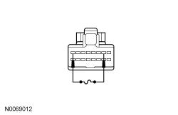  | Yes
REMOVE the jumper wire. INSTALL a new multifunction switch. REFER to Section 211-05 . TEST the system for normal operation. No REMOVE the jumper wire. GO to L3 . |
| L3 CHECK TURN SIGNAL REQUEST INPUT CIRCUIT FOR AN OPEN | |
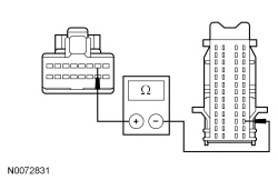  | Yes
GO to L4 . No REPAIR circuit CLS39 (VT/WH) (LH turn signal) or circuit CLS41 (GY/YE) (RH turn signal) for an open. TEST the system for normal operation. |
| L4 CHECK FOR CORRECT SJB OPERATION | |
| Yes
INSTALL a new SJB . REFER to Section 419-10 . TEST the system for normal operation. No The system is operating correctly at this time. The concern may have been caused by a loose or corroded connector. |
Pinpoint Test M: The Turn Signal Lamps Are Always On
Refer to Wiring Diagrams Cell 90 , Turn Signal/Stop/Hazard Lamps for schematic and connector information.
The Smart Junction Box (SJB) sends voltage signals to the multifunction switch. When the multifunction switch is switched to the LH or RH TURN position, the voltage signal is routed to ground. When the SJB detects the multifunction switch is in the LH or RH TURN position, the SJB sends voltage to the appropriate front turn lamps.
This pinpoint test is intended to diagnose the following:
NOTICE: Use the correct probe adapter(s) when making measurements. Failure to use the correct probe adapter(s) may damage the connector.
| Test Step | Result / Action to Take |
|---|---|
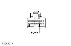
| M1 CHECK THE MULTIFUNCTION SWITCH | |
| Yes
GO to M2 . No INSTALL a new multifunction switch. REFER to Section 211-05 . CLEAR the DTCs. REPEAT the self-test. |
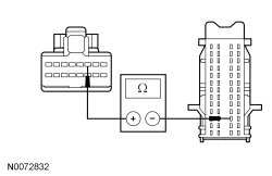
| M2 CHECK THE TURN SIGNAL REQUEST INPUT CIRCUIT FOR A SHORT TO GROUND | |
 | Yes
GO to M3 . No REPAIR circuit CLS39 (VT/WH) (LH turn signal) or circuit CLS41 (GY/YE) (RH turn signal) for a short to ground. CLEAR the DTCs. REPEAT the self-test. |
| M3 CHECK FOR CORRECT SJB OPERATION | |
| Yes
INSTALL a new SJB . REFER to Section 419-10 . TEST the system for normal operation. No The system is operating correctly at this time. The concern may have been caused by a loose or corroded connector. CLEAR any DTCs. REPEAT the self-test. |
Pinpoint Test N: One Turn Signal/Hazard Lamp Is Inoperative/Always On
Refer to Wiring Diagrams Cell 90 , Turn Signal/Stop/Hazard Lamps for schematic and connector information.
When the Smart Junction Box (SJB) detects the multifunction switch is in the LH TURN position, the SJB provides voltage to the LH front turn lamp. When the SJB detects the multifunction switch is in the RH TURN position, the SJB provides voltage to the RH front turn lamp. The rear turn lamps are controlled utilizing the rear stoplamp circuitry.
| DTC Description | Fault Trigger Conditions |
|---|---|
| A continuous DTC that sets when the SJB has temporarily shut down the output driver. The module has temporarily disabled a stoplamp output because an excessive current draw exists (such as a short to ground). The SJB cannot enable the stoplamp output until the cause of the short is corrected, the DTCs have been cleared and a successful self-test is run. |
| A continuous DTC that sets when the SJB has permanently shut down the output driver. The module has permanently disabled a stoplamp output because an excessive current draw fault (such as a short to ground) has exceeded the limits that the SJB can withstand. The cause of the excessive current draw MUST be corrected before a new SJB is installed. |
| An on-demand DTC that sets when the SJB detects an open or short to voltage on the RH front turn lamp voltage supply circuit. |
| A continuous and on-demand DTC that sets when the SJB detects a short to ground on the RH front turn lamp voltage supply circuit. |
| An on-demand DTC that sets when the SJB detects an open or short to voltage on the LH front turn lamp voltage supply circuit. |
| A continuous and on-demand DTC that sets when the SJB detects a short to ground on the LH front turn lamp voltage supply circuit. |
This pinpoint test is intended to diagnose the following:
NOTICE: Use the correct probe adapter(s) when making measurements. Failure to use the correct probe adapter(s) may damage the connector.
| Test Step | Result / Action to Take |
|---|---|
| N1 DETERMINE IF A TURN LAMP IS ALWAYS ON | |
| Yes
GO to N2 . No GO to N3 . |
| N2 CHECK THE SJB TURN LAMP OUTPUT CIRCUIT FOR A SHORT TO VOLTAGE | |
| Yes
REPAIR circuit CLS21 (BU/GN) (LH front turn lamp) or circuit CLS25 (YE/VT) (RH front turn lamp) for a short to voltage. CLEAR the DTCs. REPEAT the self-test. No GO to N9 . |
| N3 USE THE RECORDED DTCs FROM THE SJB SELF-TEST | |
| Yes
GO to N6 . No GO to N4 . |
| N4 CHECK THE BULB HOLDER FOR A SHORT TO GROUND | |
 | Yes
INSTALL a new bulb holder. TEST the system for normal operation. No GO to N5 . |
| N5 CHECK THE SJB TURN LAMP OUTPUT CIRCUIT FOR A SHORT TO GROUND | |
 | Yes
GO to N9 . No REPAIR circuit CLS21 (BU/GN) (LH turn) or circuit CLS25 (YE/VT) (RH turn) for a short to ground. CLEAR the DTCs. REPEAT the self-test After the repair: If no DTCs are present, TEST the system for normal operation If DTC B106E is present, CLEAR the DTCs and REPEAT the self-test (required to enable the turn lamp output driver if DTC B106E is present). TEST the system for normal operation. If DTC B106F is present, INSTALL a new SJB SJB . REFER to Section 419-10 . TEST the system for normal operation. |
| N6 CHECK FOR VOLTAGE TO THE FRONT TURN LAMP | |
| Yes
GO to N7 . No GO to N8 . |
| N7 CHECK FOR VOLTAGE TO THE FRONT TURN LAMP USING THE CONNECTOR GROUND | |
 | Yes
INSTALL a new bulb holder. CLEAR the DTCs. REPEAT the self-test. No REPAIR circuit GD129 (BK/YE) for an open. CLEAR the DTCs. REPEAT the self-test. |
| N8 CHECK THE SJB TURN LAMP OUTPUT CIRCUIT FOR AN OPEN | |
 | Yes
GO to N9 . No REPAIR circuit CLS21 (BU/GN) (LH turn) or circuit CLS25 (YE/VT) (RH turn) for an open. CLEAR the DTCs. REPEAT the self-test |
| N9 CHECK FOR CORRECT SJB OPERATION | |
| Yes
INSTALL a new SJB . REFER to Section 419-10 . TEST the system for normal operation. No The system is operating correctly at this time. The concern may have been caused by a loose or corroded connector. CLEAR the DTCs. REPEAT the self-test. |
Pinpoint Test O: The Hazard Lamps Are Inoperative/Always On
Refer to Wiring Diagrams Cell 90 , Turn Signal/Stop/Hazard Lamps for schematic and connector information.
The Smart Junction Box (SJB) sends a voltage signal to the hazard flasher lamp switch. The hazard flasher lamp switch is a momentary contact switch. When the hazard flasher lamp switch is engaged, the voltage signal is routed to ground. When the SJB detects a request for the hazard lamps, the SJB provides voltage to all the front turn lamps and a message to the Body Control Module B (BCM-B) to flash the rear lamps on and off.
This pinpoint test is intended to diagnose the following:
NOTICE: Use the correct probe adapter(s) when making measurements. Failure to use the correct probe adapter(s) may damage the connector.
| Test Step | Result / Action to Take |
|---|---|
| O1 CHECK THE RECORDED DTCs FROM THE SJB SELF-TEST | |
| Yes
GO to O2 . No GO to O4 . |
| O2 CHECK THE HAZARD FLASHER LAMP SWITCH | |
| Yes
GO to O3 . No INSTALL a new hazard flasher lamp switch. REFER to Hazard Flasher Lamp Switch in this section. CLEAR the DTCs. REPEAT the self-test. |
| O3 CHECK THE HAZARD FLASHER REQUEST INPUT CIRCUIT FOR A SHORT TO GROUND | |
 | Yes
GO to O7 . No REPAIR circuit CLS32 (BN/YE) for a short to ground. CLEAR the DTCs. REPEAT the self-test. |
| O4 CHECK FOR A VOLTAGE REFERENCE SIGNAL TO THE HAZARD FLASHER LAMP SWITCH | |
 | Yes
GO to O6 . No GO to O5 . |
| O5 CHECK THE HAZARD FLASH REQUEST INPUT CIRCUIT FOR AN OPEN | |
 | Yes
GO to O7 . No REPAIR circuit CLS32 (BN/YE) for an open. TEST the system for normal operation. |
| O6 CHECK THE HAZARD FLASHER LAMP SWITCH GROUND CIRCUIT FOR AN OPEN | |
 | Yes
INSTALL a new hazard flasher lamp switch. REFER to Hazard Flasher Lamp Switch in this section. CLEAR the DTCs. REPEAT the self-test. No REPAIR circuit GD116 (BK/VT) for an open. TEST the system for normal operation. |
| O7 CHECK FOR CORRECT SJB OPERATION | |
| Yes
INSTALL a new SJB . REFER to Section 419-10 . TEST the system for normal operation. No The system is operating correctly at this time. The concern may have been caused by a loose or corroded connector. CLEAR the DTCs. REPEAT the self-test. |
Pinpoint Test P: The Sequential Feature Of A Rear Turn Lamp Is Inoperative
Refer to Wiring Diagrams Cell 90 , Turn Signal/Stop/Hazard Lamps for schematic and connector information.
When the Smart Junction Box (SJB) detects the multifunction switch in the LH or RH TURN position, the SJB sends a message to the Body Control Module B (BCM-B) indicating a LH or RH turn signal. The BCM-B then flashes the rear lamp sequentially from the inboard lamp to the outboard lamp.
The BCM-B sends a voltage signal to each inboard LED lamp through a feedback circuit. If the BCM-B detects a fault from the feedback circuit, the turn lamps flash fast for the side affected (LH or RH) and the sequential feature is disabled.
| DTC Description | Fault Trigger Conditions |
|---|---|
| A continuous and on-demand DTC that sets when the BCM-B detects an inoperative inboard LED lamp or a short to ground from the left rear turn lamp feedback circuit. |
| A continuous and on-demand DTC that sets when the BCM-B detects an inoperative inboard LED lamp or an open/short to voltage from the left rear turn lamp feedback circuit. |
| A continuous and on-demand DTC that sets when the BCM-B detects an inoperative inboard LED lamp or a short to ground from the right rear turn lamp feedback circuit. |
| A continuous and on-demand DTC that sets when the BCM-B detects an inoperative inboard LED lamp or an open/short to voltage from the right rear turn lamp feedback circuit. |
This pinpoint test is intended to diagnose the following:
NOTICE: Use the correct probe adapter(s) when making measurements. Failure to use the correct probe adapter(s) may damage the connector.
| Test Step | Result / Action to Take | ||||||||||||||||||||||||||||||||
|---|---|---|---|---|---|---|---|---|---|---|---|---|---|---|---|---|---|---|---|---|---|---|---|---|---|---|---|---|---|---|---|---|---|
| P1 CHECK THE STOPLAMP OPERATION | |||||||||||||||||||||||||||||||||
| Yes
GO to P2 . No REFER to Stoplamps in this section. | ||||||||||||||||||||||||||||||||
| P2 CHECK FOR REAR LAMP CIRCUIT DTC | |||||||||||||||||||||||||||||||||
| Yes
GO to P5 . No GO to P3 . | ||||||||||||||||||||||||||||||||
| P3 CHECK THE REAR JUMPER HARNESS FOR SHORTS | |||||||||||||||||||||||||||||||||
| Yes
GO to P4 . No REPAIR or INSTALL a new rear lamp jumper harness. CLEAR the DTCs. REPEAT the self-test. | ||||||||||||||||||||||||||||||||
| P4 CHECK THE REAR TURN LAMPS CIRCUITS FOR A SHORT TOGETHER | |||||||||||||||||||||||||||||||||
LH Rear Lamp
RH Rear Lamp
 | Yes
GO to P9 . No REPAIR the circuits in question for a short to each other. TEST the system for normal operation. | ||||||||||||||||||||||||||||||||
| P5 CHECK REAR LAMP OUTAGE CIRCUIT | |||||||||||||||||||||||||||||||||
 | Yes
GO to P6 . No GO to P7 . | ||||||||||||||||||||||||||||||||
| P6 CHECK THE REAR JUMPER HARNESS | |||||||||||||||||||||||||||||||||
| Yes
INSTALL a new LED lamp. CLEAR the DTCs. REPEAT the self-test. TEST the system for normal operation. No REPAIR or INSTALL a new rear lamp jumper harness. CLEAR the DTCs. REPEAT the self-test. | ||||||||||||||||||||||||||||||||
| P7 CHECK REAR LAMP OUTAGE CIRCUIT FOR A SHORT TO VOLTAGE | |||||||||||||||||||||||||||||||||
| Yes
REPAIR circuit CLS54 (BU/OG) (LH rear lamp) or circuit CLS55 (GN/BU) (RH rear lamp) for a short to voltage. CLEAR the DTCs. REPEAT the self-test. TEST the system for normal operation. No GO to P8 . | ||||||||||||||||||||||||||||||||
| P8 CHECK REAR LAMP OUTAGE CIRCUIT FOR A SHORT TO GROUND | |||||||||||||||||||||||||||||||||
 | Yes
GO to P9 . No REPAIR circuit CLS54 (BU/OG) (LH rear lamp) or circuit CLS55 (GN/BU) (RH rear lamp) for a short to ground. CLEAR the DTCs. REPEAT the self-test. TEST the system for normal operation. | ||||||||||||||||||||||||||||||||
| P9 CHECK FOR CORRECT BCM-B OPERATION | |||||||||||||||||||||||||||||||||
| Yes
INSTALL a new BCM-B . REFER to Section 419-10 . TEST the system for normal operation. No The system is operating correctly at this time. The concern may have been caused by a loose or corroded connector. |