
FLU77-4 or equivalent


105-R025D or equivalent
SECTION 417-01: Exterior Lighting
| 2014 Mustang Workshop Manual
|
DIAGNOSIS AND TESTING
| Procedure revision date: 01/07/2013
|
| Fluke 77-IV Digital Multimeter
FLU77-4 or equivalent |
| Vehicle Communication Module (VCM) and Integrated Diagnostic System (IDS) software with appropriate hardware, or equivalent scan tool
|
| Flex Probe Kit
105-R025D or equivalent |
Principles of Operation
NOTE: The Smart Junction Box (SJB) is also known as the Generic Electronic Module (GEM).
Exterior Lighting
The SJB monitors the headlamp switch position by sending voltage signals on multiple circuits to the headlamp switch. There is one circuit for each headlamp switch position. At any given time, one of the signal circuits is switched to ground.
If the SJB does not detect any of the inputs to the headlamp switch are active (switched to ground) for 5 seconds, the SJB turns the parking lamps and headlamps on and keeps them on until the battery saver feature times out.
Additionally, if the SJB detects multiple headlamp switch input circuits short to ground, the SJB turns the parking lamps and headlamps on and keeps them on until the battery saver feature times out.
Refer to Exterior Lighting in the Description and Operation portion of this section for information regarding the Battery Saver feature.
If either situation occurs, the SJB cannot be ruled immediately as being at fault. This is normal behavior of the SJB design as it has detected a fault with the inputs from the headlamp switch.
The SJB monitors the multifunction switch for a flash-to-pass or high beam request. There are 2 voltage reference circuits monitoring this. When the multifunction switch is in the FLASH-TO-PASS or HIGH BEAM position, the voltage signal is routed to ground.
NOTE: The flash-to-pass feature does not require any input from the headlamp switch.
When the SJB receives an input requesting the headlamps on, the SJB supplies voltage to the low beams. If the low beams are on and the SJB receives a request for high beams (or a flash-to-pass request), the SJB energizes an internal relay which routes voltage to the headlamps.
Headlamp Functionality
The High Intensity Discharge (HID) headlamps utilize a second (hot at all times) voltage feed to the HID ballasts.
When the low beams are requested (based on inputs to the SJB ), the HID ballasts energize and provide high voltage to the HID bulbs.
When the high beams are requested, the HID ballasts remain powered and a shutter within each headlamp is activated. This changes the headlamp beam pattern to illuminate a greater distance.
If the low beams are off when the flash-to-pass is requested, the HID ballasts and the shutters within the headlamps are activated for approximately 0.5 second. If the low beams are on when the flash-to-pass is requested, the shutters within the headlamps are activated as long as the multifunction switch is held in the FLASH-TO-PASS position.
Field-Effect Transistor (FET) Protection
Field-Effect Transistor (FET) is a type of transistor that when used with module software can be used to monitor and control current flow on module outputs. The FET protection strategy is used to prevent module damage in the event of excessive current flow.
The SJB utilizes a FET protective circuit strategy for many of its outputs (for example, a headlamp output circuit). Output loads (current level) are monitored for excessive current (typically short circuits) and are shut down (turns off the voltage or ground provided by the module) when a fault event is detected. A continuous DTC is stored at the fault event and a cumulative counter is started.
When the demand for the output is no longer present, the module resets the FET circuit protection to allow the circuit to function. The next time the driver requests a circuit to activate that has been shut down by a previous short ( FET protection) and the circuit remains shorted, the FET protection shuts off the circuit again and the cumulative counter advances.
When the excessive circuit load occurs often enough, the module shuts down the output until a repair procedure is carried out. Each FET protected circuit has 3 predefined levels of short circuit tolerance based on the harmful effect of each circuit fault on the FET and the ability of the FET to withstand it. A module lifetime level of fault events is established based upon the durability of the FET . If the total tolerance level is determined to be 600 fault events, the 3 predefined levels would be 200, 400 and 600 fault events.
When each tolerance level is reached, the continuous DTC that was stored on the first failure cannot be cleared by a command to clear the continuous DTCs. The module does not allow this code to be cleared or the circuit restored to normal operation until a successful self-test proves that the fault has been repaired. After the self-test has successfully completed (no on-demand DTCs present), DTC B106E and the associated continuous DTC (the DTC related to the shorted circuit) automatically clear and the circuit function returns.
When the first or second level is reached, the continuous DTC (associated with the short circuit) sets along with DTC B106E. These DTCs can be cleared using the module on-demand self-test, then the Clear DTC operation on the scan tool (if the on-demand test shows the fault corrected). The module never resets the fault event counter to zero and continues to advance the fault event counter as short circuit fault events occur.
If the number of short circuit fault events reach the third level, then DTCs B106F and B1342 set along with the associated continuous DTC. This DTC cannot be cleared and the module must be replaced.
The SJB FET protected output circuits for the headlamp system are the LH low beam and the RH low beam output circuits.
Inspection and Verification
Visual Inspection Chart
| Mechanical | Electrical |
|---|---|
|
|
NOTE: Make sure to use the latest scan tool software release.
If the cause is not visually evident, connect the scan tool to the Data Link Connector (DLC).NOTE: The Vehicle Communication Module (VCM) LED prove-out confirms power and ground from the DLC are provided to the VCM .
If the scan tool does not communicate with the VCM :Symptom Chart
Diagnostics in this manual assume a certain skill level and knowledge of Ford-specific diagnostic practices. Refer to Diagnostic Methods in Section 100-00 for information about these practices.
| Condition | Possible Sources | Action |
|---|---|---|
|
|
|
|
| |
|
|
|
|
|
|
|
|
|
|
| |
|
| |
|
|
Pinpoint Tests
Pinpoint Test A: Both High Beams Are Inoperative
Refer to Wiring Diagrams Cell 85 , Headlamps/Autolamps for schematic and connector information.
When the headlamp switch is placed in the HEADLAMPS ON position, the Smart Junction Box (SJB) monitors the high beam request circuit from the multifunction switch. When the multifunction switch is placed in the HIGH BEAM position, the signal is routed to ground. The SJB then energizes the high beam relay (integrated into the SJB ) which supplies voltage to the headlamps.
This pinpoint test is intended to diagnose the following:
NOTICE: Use the correct probe adapter(s) when making measurements. Failure to use the correct probe adapter(s) may damage the connector.
| Test Step | Result / Action to Take |
|---|---|
| A1 CHECK THE HIGH BEAM INDICATOR | |
| Yes
VERIFY the SJB fuse 23 (15A) is OK. If OK, GO to A5 . If not OK, REFER to the Wiring Diagrams Manual to identify the possible causes of the circuit short. No GO to A2 . |
| A2 CHECK FOR VOLTAGE TO THE MULTIFUNCTION SWITCH | |
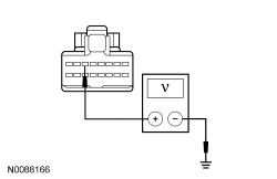 | Yes
GO to A3 . No GO to A4 . |
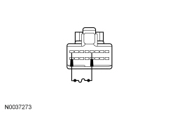
| A3 BYPASS THE MULTIFUNCTION SWITCH | |
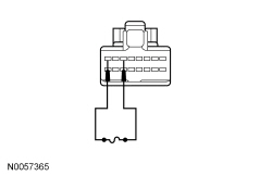 | Yes
REMOVE the jumper wire. INSTALL a new multifunction switch. REFER to Section 211-05 . TEST the system for normal operation. No REMOVE the jumper wire. REPAIR circuit GD116 (BK/VT) for an open. |
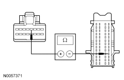
| A4 CHECK THE HIGH BEAM REQUEST INPUT CIRCUIT FOR AN OPEN | |
 | Yes
GO to A6 . No REPAIR circuit CLF17 (WH/OG) for an open. TEST the system for normal operation. |
| A5 CHECK THE SJB HIGH BEAM OUTPUT CIRCUIT FOR AN OPEN | |
NOTE: An assistant may be required to listen for the high beam shutters activating for this step. 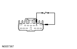 | Yes
REMOVE the jumper wire. GO to A6 . No REMOVE the jumper wire. REPAIR circuit CLF08 (YE/VT) for an open. TEST the system for normal operation. |
| A6 CHECK FOR CORRECT SJB OPERATION | |
| Yes
INSTALL a new SJB . REFER to Section 419-10 . TEST the system for normal operation. No The system is operating correctly at this time. The concern may have been caused by a loose or corroded connector. |
Pinpoint Test B: One Low Beam Headlamp Is Inoperative
Diagnostics in this manual assume a certain skill level and knowledge of Ford-specific diagnostic practices. Refer to Diagnostic Methods in Section 100-00 for information about these practices.
Refer to Wiring Diagrams Cell 85 , Headlamps/Autolamps for schematic and connector information.
When the Smart Junction Box (SJB) detects the headlamp switch in the HEADLAMPS ON position and the multifunction switch in the LOW BEAM position, the SJB provides voltage to the LH and RH low beam headlamps.
The headlamps utilize a second (hot at all times) voltage feed to the ballasts from the Battery Junction Box (BJB).
When the ballasts receive the headlamp on voltage from the SJB , the ballasts provide high voltage to the HID bulbs.
| DTC Description | Fault Trigger Conditions |
|---|---|
| A continuous DTC that sets when the SJB has temporarily shut down the output driver. The module has temporarily disabled a low beam output because an excessive current draw exists (such as a short to ground). The SJB cannot enable the low beam output until the cause of the short is corrected, the DTCs have been cleared and a successful self-test is run. |
| A continuous DTC that sets when the SJB has permanently shut down the output driver. The module has permanently disabled a low beam output because an excessive current draw fault (such as a short to ground) has exceeded the limits that the SJB can withstand. The cause of the excessive current draw MUST be corrected before a new SJB is installed. |
| An on-demand DTC that sets when the SJB detects an open from the RH low beam output circuit. |
| A continuous and on-demand DTC that sets when the SJB detects a short to ground from the RH low beam output circuit. |
| An on-demand DTC that sets when the SJB detects an open from the LH low beam output circuit. |
| A continuous and on-demand DTC that sets when the SJB detects a short to ground from the LH low beam output circuit. |
NOTICE: Use the correct probe adapter(s) when making measurements. Failure to use the correct probe adapter(s) may damage the connector.
| Test Step | Result / Action to Take | ||||||||||||||||||||||||||||||||
|---|---|---|---|---|---|---|---|---|---|---|---|---|---|---|---|---|---|---|---|---|---|---|---|---|---|---|---|---|---|---|---|---|---|
| B1 CHECK FOR VOLTAGE TO THE HEADLAMP | |||||||||||||||||||||||||||||||||
 | Yes
GO to B2 . No VERIFY the SJB fuse 7 (10A) (LH low beam) or fuse 8 (10A) (RH low beam) is OK. GO to B6 . | ||||||||||||||||||||||||||||||||
| B2 CHECK BALLAST SUPPLY VOLTAGE TO THE HEADLAMP | |||||||||||||||||||||||||||||||||
| Yes
GO to B3 . No VERIFY the BJB fuse 26 (20A) (LH headlamp) or fuse 27 (20A) (RH headlamp) is OK. If OK, REPAIR the circuit in question for an open. TEST the system for normal operation. If not OK, REFER to the Wiring Diagrams Manual to identify the possible causes of the circuit short. GO to B9 . | ||||||||||||||||||||||||||||||||
| B3 CHECK FOR VOLTAGE TO THE HEADLAMP USING THE CONNECTOR GROUND | |||||||||||||||||||||||||||||||||
| Yes
GO to B4 . No REPAIR circuit GD129 (BK/YE) or circuit GD123 (BK/GY) for an open. TEST the system for normal operation. | ||||||||||||||||||||||||||||||||
| B4 CHECK THE HEADLAMP BULB HARNESS FOR AN OPEN OR SHORT | |||||||||||||||||||||||||||||||||
| Yes
GO to B5 . No INSTALL a new headlamp bulb harness. TEST the system for normal operation. | ||||||||||||||||||||||||||||||||
| B5 CHECK THE BALLAST | |||||||||||||||||||||||||||||||||
| Yes
INSTALL a new ballast. REFER to Ballast in this section. TEST the system for normal operation. No INSTALL a new HID bulb. REFER to Headlamp Bulb in this section. TEST the system for normal operation. | ||||||||||||||||||||||||||||||||
| B6 USE THE RECORDED DTCs FROM THE SJB SELF-TEST | |||||||||||||||||||||||||||||||||
| Yes
GO to B7 . No GO to B8 . | ||||||||||||||||||||||||||||||||
| B7 CHECK THE SJB LOW BEAM OUTPUT CIRCUIT FOR AN OPEN | |||||||||||||||||||||||||||||||||
 | Yes
GO to B11 . No REPAIR circuit CLF04 (BN/BU) (LH headlamp) or circuit CLF05 (BU/GN) (RH headlamp) for an open. CLEAR the DTCs. REPEAT the self-test. | ||||||||||||||||||||||||||||||||
| B8 ISOLATE THE HEADLAMP AS THE CAUSE OF THE SHORT | |||||||||||||||||||||||||||||||||
| Yes
GO to B9 . No GO to B10 . | ||||||||||||||||||||||||||||||||
| B9 CHECK THE HEADLAMP BULB HARNESS FOR A SHORT TO GROUND | |||||||||||||||||||||||||||||||||
| Yes
INSTALL a new ballast. REFER to Ballast in this section. TEST the system for normal operation. No INSTALL a new headlamp bulb harness. TEST the system for normal operation. | ||||||||||||||||||||||||||||||||
| B10 CHECK THE SJB LOW BEAM OUTPUT CIRCUIT FOR A SHORT TO GROUND | |||||||||||||||||||||||||||||||||
| Yes
GO to B11 . No REPAIR circuit CLF04 (BN/BU) (LH headlamp) or circuit CLF05 (BU/GN) (RH headlamp) for a short to ground. After the repair: If no DTCs are present, TEST the system for normal operation. If DTC B106E is present, CLEAR the DTCs and REPEAT the self-test (required to enable the low beam output driver if DTC B106E is present) . TEST the system for normal operation. If DTC B106F is present, INSTALL a new SJB . REFER to Section 419-10 . TEST the system for normal operation. | ||||||||||||||||||||||||||||||||
| B11 CHECK FOR CORRECT SJB OPERATION | |||||||||||||||||||||||||||||||||
| Yes
INSTALL a new SJB . REFER to Section 419-10 . TEST the system for normal operation. No The system is operating correctly at this time. The concern may have been caused by a loose or corroded connector. CLEAR the DTCs. REPEAT the self-test. | ||||||||||||||||||||||||||||||||
Pinpoint Test C: One High Beam Headlamp Is Inoperative
Refer to Wiring Diagrams Cell 85 , Headlamps/Autolamps for schematic and connector information.
Diagnostics in this manual assume a certain skill level and knowledge of Ford-specific diagnostic practices. Refer to Diagnostic Methods in Section 100-00 for information about these practices.
When the Smart Junction Box (SJB) detects the headlamp switch in the HEADLAMPS ON position and the multifunction switch in the HIGH BEAM position, the SJB energizes the high beam relay (integrated into the SJB ). When the relay is energized, the relay routes voltage to the headlamps.
The High Intensity Discharge (HID) headlamps utilize a shutter within each headlamp. When the shutter is activated, the headlamp beam pattern changes to illuminate a greater distance.
NOTICE: Use the correct probe adapter(s) when making measurements. Failure to use the correct probe adapter(s) may damage the connector.
| Test Step | Result / Action to Take | ||||||||||||||||||||||||
|---|---|---|---|---|---|---|---|---|---|---|---|---|---|---|---|---|---|---|---|---|---|---|---|---|---|
| C1 CHECK THE LOW BEAM OPERATION | |||||||||||||||||||||||||
| Yes
GO to C2 . No GO to Pinpoint Test B . | ||||||||||||||||||||||||
| C2 CHECK FOR VOLTAGE TO THE HEADLAMP | |||||||||||||||||||||||||
| Yes
INSTALL a new headlamp assembly. REFER to Headlamp Assembly in this section. TEST the system for normal operation. No REPAIR circuit CLF08 (YE/VT) for an open. TEST the system for normal operation. | ||||||||||||||||||||||||
Pinpoint Test D: The Low Beam(s) Are Always On
Diagnostics in this manual assume a certain skill level and knowledge of Ford-specific diagnostic practices. Refer to Diagnostic Methods in Section 100-00 for information about these practices.
Refer to Wiring Diagrams Cell 85 , Headlamps/Autolamps for schematic and connector information.
The Smart Junction Box (SJB) sends voltage signals to the headlamp switch (OFF, PARKING LAMPS and HEADLAMPS). At any given time, the headlamp switch routes one of the input circuits to ground.
When the SJB detects the headlamp switch in the HEADLAMPS ON position (or a fault with one of the headlamp switch input circuits for more than 5 seconds) and the multifunction switch in the LOW BEAM position, the SJB provides voltage to the low beam headlamps.
The headlamps utilize a second (hot at all times) voltage feed to the HID ballasts.
When the ballasts receive the headlamp on voltage from the SJB , the ballasts provide high voltage to the HID bulbs.
| DTC Description | Fault Trigger Conditions |
|---|---|
| An on-demand DTC that can set when the SJB detects the headlamps on input circuit is short to ground. |
| An on-demand DTC that can set when the SJB detects multiple headlamp switch inputs active at the same time. |
| An on-demand DTC that sets when the SJB detects the headlamp switch off input circuit open. |
| An on-demand DTC that sets when the SJB detects the RH low beam output circuit shorted to voltage. |
| An on-demand DTC that sets when the SJB detects the LH low beam output circuit shorted to voltage. |
NOTICE: Use the correct probe adapter(s) when making measurements. Failure to use the correct probe adapter(s) may damage the connector.
| Test Step | Result / Action to Take | ||||||||||||||||||||||||
|---|---|---|---|---|---|---|---|---|---|---|---|---|---|---|---|---|---|---|---|---|---|---|---|---|---|
| D1 CHECK FOR AUTOLAMP DTCs | |||||||||||||||||||||||||
| Yes
GO to Pinpoint Test H . No GO to D2 . | ||||||||||||||||||||||||
| D2 CHECK THE SJB HEADLAMP SWITCH PIDs | |||||||||||||||||||||||||
NOTE: Make sure the headlamp switch is lined up in the correct position when monitoring the PIDs. NOTE: Only one PID should indicate ON at each headlamp switch position. | Yes
GO to D7 . No If the PID HDLMP_AUT_CKT disagrees, GO to Pinpoint Test H . Otherwise, GO to D3 . | ||||||||||||||||||||||||
| D3 CHECK FOR VOLTAGE TO THE HEADLAMP SWITCH | |||||||||||||||||||||||||
 | Yes
GO to D4 . No GO to D5 . | ||||||||||||||||||||||||
| D4 CHECK FOR VOLTAGE BETWEEN THE OFF CIRCUIT AND GROUND | |||||||||||||||||||||||||
| Yes
INSTALL a new headlamp switch. REFER to Headlamp Switch in this section. CLEAR the DTCs. REPEAT the self-test. No REPAIR circuit GD116 (BK/VT) for an open. CLEAR the DTCs. REPEAT the self-test. | ||||||||||||||||||||||||
| D5 CHECK THE HEADLAMP SWITCH INPUT CIRCUITS FOR A SHORT TO GROUND | |||||||||||||||||||||||||
| Yes
GO to D6 . No REPAIR the circuit in question for a short to ground. CLEAR the DTCs. REPEAT the self-test. | ||||||||||||||||||||||||
| D6 CHECK THE HEADLAMP SWITCH INPUT CIRCUITS FOR AN OPEN | |||||||||||||||||||||||||
 | Yes
GO to D7 . No REPAIR the circuit in question for an open. CLEAR the DTCs. REPEAT the self-test. | ||||||||||||||||||||||||
| D7 CHECK THE SJB OUTPUT | |||||||||||||||||||||||||
| Yes
GO to D8 . No GO to D9 . | ||||||||||||||||||||||||
| D8 CHECK THE SJB LOW BEAM OUTPUT CIRCUIT FOR A SHORT TO VOLTAGE | |||||||||||||||||||||||||
| Yes
REPAIR circuit CLF04 (BN/BU) (LH headlamp) or circuit CLF05 (BU/GN) (RH headlamp) for a short to voltage. CLEAR the DTCs. REPEAT the self-test. No INSTALL a new ballast. REFER to Ballast in this section. TEST the system for normal operation. | ||||||||||||||||||||||||
| D9 CHECK FOR CORRECT SJB OPERATION | |||||||||||||||||||||||||
| Yes
INSTALL a new SJB . REFER to Section 419-10 . TEST the system for normal operation. No The system is operating correctly at this time. The concern may have been caused by a loose or corroded connector. CLEAR the DTCs. REPEAT the self-test. | ||||||||||||||||||||||||
Pinpoint Test E: The High Beam(s) Are Always On
Diagnostics in this manual assume a certain skill level and knowledge of Ford-specific diagnostic practices. Refer to Diagnostic Methods in Section 100-00 for information about these practices.
Refer to Wiring Diagrams Cell 85 , Headlamps/Autolamps for schematic and connector information.
The Smart Junction Box (SJB) sends a voltage signal to the multifunction switch. When the multifunction switch is placed in the FLASH-TO-PASS or HIGH BEAM position, the voltage signal is routed to ground. When the SJB detects a request for flash-to-pass or high beams (when the low beams are on), the SJB energizes the high beam relay (integrated into the SJB ), which routes voltage to the headlamps.
NOTE: If the high beam circuit is supplied voltage when the headlamps are not on, the headlamps do not illuminate. The circuit only supplies voltage to activate the high beam shutters within the headlamp assemblies. The low beams must be on for light to illuminate from the headlamps.
NOTICE: Use the correct probe adapter(s) when making measurements. Failure to use the correct probe adapter(s) may damage the connector.
| Test Step | Result / Action to Take | ||||||||||||||||||||||||
|---|---|---|---|---|---|---|---|---|---|---|---|---|---|---|---|---|---|---|---|---|---|---|---|---|---|
| E1 CHECK FOR DTC B1510 OR DTC B2A23 | |||||||||||||||||||||||||
| Yes
GO to E2 . No GO to E4 . | ||||||||||||||||||||||||
| E2 CHECK THE MULTIFUNCTION SWITCH | |||||||||||||||||||||||||
| Yes
GO to E3 . No INSTALL a new multifunction switch. REFER to Section 211-05 . CLEAR the DTCs. REPEAT the self-test. | ||||||||||||||||||||||||
| E3 CHECK THE HIGH BEAM AND FLASH-TO-PASS REQUEST INPUT CIRCUITS FOR A SHORT TO GROUND | |||||||||||||||||||||||||
 | Yes
GO to E5 . No REPAIR the circuit in question for a short to ground. CLEAR the DTCs. REPEAT the self-test. | ||||||||||||||||||||||||
| E4 CHECK THE SJB HIGH BEAM OUTPUT CIRCUIT FOR A SHORT TO VOLTAGE | |||||||||||||||||||||||||
NOTE: If only an individual high beam is always on, install a new headlamp assembly. Refer to Headlamp Assembly in this section.
| Yes
REPAIR circuit CLF08 (YE/VT) for a short to voltage. CLEAR the DTCs. REPEAT the self-test. No GO to E5 . | ||||||||||||||||||||||||
| E5 CHECK FOR CORRECT SJB OPERATION | |||||||||||||||||||||||||
| Yes
INSTALL a new SJB . REFER to Section 419-10 . TEST the system for normal operation. No The system is operating correctly at this time. The concern may have been caused by a loose or corroded connector. CLEAR the DTCs. REPEAT the self-test. | ||||||||||||||||||||||||
Pinpoint Test F: The Flash-To-Pass Feature Is Inoperative
Refer to Wiring Diagrams Cell 85 , Headlamps/Autolamps for schematic and connector information.
The Smart Junction Box (SJB) sends a voltage signal to the multifunction switch. When the multifunction switch is placed in the FLASH-TO-PASS position, the voltage signal is routed to ground. When the SJB detects a request for flash-to-pass, the SJB provides voltage to the high beam headlamps.
If the low beams are off when flash-to-pass is requested, the HID ballasts and the shutters within the headlamps are activated for approximately 0.5 seconds. If the low beams are on when flash-to-pass is requested, the shutters within the headlamps are activated as long as the multifunction switch is held in the FLASH-TO-PASS position.
This pinpoint test is intended to diagnose the following:
NOTICE: Use the correct probe adapter(s) when making measurements. Failure to use the correct probe adapter(s) may damage the connector.
| Test Step | Result / Action to Take |
|---|---|
| F1 VERIFY THE HIGH BEAM HEADLAMP OPERATION | |
| Yes
GO to F2 . No GO to Pinpoint Test A . |
| F2 CHECK THE MULTIFUNCTION SWITCH | |
 | Yes
REMOVE the jumper wire. INSTALL a new multifunction switch. REFER to Section 211-05 . TEST the system for normal operation. No REMOVE the jumper wire. GO to F3 . |
| F3 CHECK THE FLASH-TO-PASS REQUEST INPUT CIRCUIT FOR AN OPEN | |
 | Yes
GO to F4 . No REPAIR circuit CLF27 (GN/BN) for an open. TEST the system for normal operation. |
| F4 CHECK FOR CORRECT SJB OPERATION | |
| Yes
INSTALL a new SJB . REFER to Section 419-10 . TEST the system for normal operation. No The system is operating correctly at this time. The concern may have been caused by a loose or corroded connector. |