
FLU77-4 or equivalent


105-R025D or equivalent
SECTION 417-01: Exterior Lighting
| 2014 Mustang Workshop Manual
|
DIAGNOSIS AND TESTING
| Procedure revision date: 01/07/2013
|
| Fluke 77-IV Digital Multimeter
FLU77-4 or equivalent |
| Vehicle Communication Module (VCM) and Integrated Diagnostic System (IDS) software with appropriate hardware, or equivalent scan tool
|
| Flex Probe Kit
105-R025D or equivalent |
Principles of Operation
NOTE: For the perimeter lighting feature, refer to Section 501-14 .
NOTE: The Smart Junction Box (SJB) is also known as the Generic Electronic Module (GEM).
Exterior Lighting
The SJB monitors the headlamp switch position by sending voltage signals on multiple circuits to the headlamp switch. There is one circuit for each headlamp switch position. At any given time, one of the signal circuits is switched to ground.
If the SJB does not detect any of the inputs to the headlamp switch is active (switched to ground) for 5 seconds, the SJB turns the parking lamps and headlamps on and keeps them on until the battery saver feature times out.
Additionally, if the SJB detects multiple headlamp switch input circuits short to ground, the SJB turns the parking lamps and headlamps on and keeps them on until the battery saver feature times out.
Refer to Exterior Lighting for information regarding the Battery Saver feature.
If the above situation occurs, the SJB cannot be ruled immediately as being at fault. This is normal behavior of the SJB design as it has detected a fault with the inputs from the headlamp switch.
Autolamps Feature
The SJB monitors the light sensor with a voltage reference signal. The light sensor input to the SJB varies with the ambient light conditions.
When the SJB receives an input from the headlamp switch indicating a request for the autolamps, the SJB monitors the light sensor for the ambient light condition. If the SJB determines the ambient light level is dark, the SJB supplies voltage to the exterior lamps.
If the ignition switch is already in the RUN position and the vehicle enters a dark/lighted area (such as when entering/exiting a non-lighted tunnel during the daytime), the transition from light to dark (or dark to light) needs to last 15 seconds before the SJB turns the exterior lamps on or off. This strategy is to prevent the exterior lamps from unnecessarily flashing on and off.
The SJB does react quicker under extreme light conditions. If the SJB has detected a very dark condition, the exterior lamps are turned on after 1.5 seconds. If the SJB has detected a very high ambient light level, the exterior lamps are turned off after 4 seconds.
Headlamps On With Wipers On Feature
If the headlamp switch is in the AUTOLAMPS ON position and the front wipers are on for more than 10 seconds (except during a mist wipe or while the wipers are on to clear washer fluid during a wash condition), the exterior lamps are turned on. The exterior lamps are turned off when the ignition switch is changed to the OFF or ACC position, the headlamp switch is placed in the OFF position, or the front wipers are off for more than 30 seconds. The exception to this is when the exterior lights are on because of darkness determined by the light sensor.
For diagnostics regarding the headlamps on with wipers on feature, refer to Section 501-16 .
Inspection and Verification
Visual Inspection Chart
| Mechanical | Electrical |
|---|---|
|
|
NOTE: Make sure to use the latest scan tool software release.
If the cause is not visually evident, connect the scan tool to the Data Link Connector (DLC).NOTE: The Vehicle Communication Module (VCM) LED prove-out confirms power and ground from the DLC are provided to the VCM .
If the scan tool does not communicate with the VCM :Symptom Chart
| Condition | Possible Sources | Action |
|---|---|---|
|
| |
|
|
Pinpoint Tests
Pinpoint Test G: The Autolamps Are Inoperative
Refer to Wiring Diagrams Cell 85 , Headlamps/Autolamps for schematic and connector information.
When the Smart Junction Box (SJB) detects the headlamp switch in the AUTOLAMPS ON position, the SJB monitors the light sensor input. The light sensor determines the amount of light based on the input received from the ambient lighting conditions. When the ambient light level has reached a point (determined by the internal programming of the SJB ), the SJB provides voltage to the headlamps, parking and license plate lamps.
This pinpoint test is intended to diagnose the following:
NOTICE: Use the correct probe adapter(s) when making measurements. Failure to use the correct probe adapter(s) may damage the connector.
| Test Step | Result / Action to Take |
|---|---|
| G1 CHECK THE MANUAL HEADLAMP OPERATION | |
| Yes
GO to G2 . No REFER to Headlamps or Parking, Rear and License Plate Lamps in this section. |
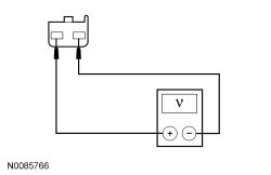
| G2 CHECK FOR VOLTAGE TO THE LIGHT SENSOR | |
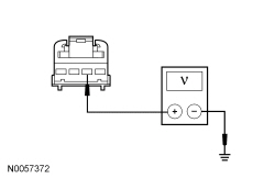  | Yes
INSTALL a new light sensor. REFER to Light Sensor in this section. TEST the system for normal operation. No GO to G3 . |
| G3 CHECK FOR CORRECT SJB OPERATION | |
| Yes
INSTALL a new SJB . REFER to Section 419-10 . TEST the system for normal operation. No The system is operating correctly at this time. The concern may have been caused by a loose or corroded connector. CLEAR the DTCs. REPEAT the self-test. |
Pinpoint Test H: The Autolamps Are On Continuously
Refer to Wiring Diagrams Cell 85 , Headlamps/Autolamps for schematic and connector information.
The Smart Junction Box (SJB) sends a voltage signal to the headlamp switch and light sensor.
When the headlamp switch is placed in the AUTOLAMPS ON position, the voltage signal is routed to ground. When the SJB detects the headlamp switch in the AUTOLAMPS ON position, the SJB monitors the light sensor input. The light sensor determines the amount of light based on the input received from the ambient lighting conditions. When the ambient light level has reached a point (determined by the internal programming of the SJB ), the SJB provides voltage to the headlamps, parking and license plate lamps.
| DTC Description | Fault Trigger Conditions |
|---|---|
| An on-demand DTC that sets when the SJB detects the autolamps on input circuit shorted to ground. |
| An on-demand DTC that sets when the SJB detects an open on the light sensor input circuit. |
| A continuous and on-demand DTC that sets when the SJB detects a short to ground on the light sensor input circuit. |
| An on-demand DTC that sets when the SJB detects a short to ground from the wipers on input circuit. |
This pinpoint test is intended to diagnose the following:
NOTICE: Use the correct probe adapter(s) when making measurements. Failure to use the correct probe adapter(s) may damage the connector.
| Test Step | Result / Action to Take |
|---|---|
| H1 CHECK THE SJB AUTOLAMP ON REQUEST PID | |
NOTE: Make sure the headlamp switch is lined up in the correct position when monitoring the PID. | Yes
GO to H5 . No GO to H2 . |
| H2 CHECK FOR A VOLTAGE SIGNAL TO THE HEADLAMP SWITCH | |
 | Yes
INSTALL a new headlamp switch. REFER to Headlamp Switch in this section. CLEAR the DTCs. REPEAT the self-test. No GO to H3 . |
| H3 CHECK THE AUTOLAMPS ON REQUEST INPUT CIRCUIT FOR A SHORT TO GROUND | |
 | Yes
GO to H4 . No REPAIR circuit CLF19 (VT/GN) for a short to ground. CLEAR the DTCs. REPEAT the self-test. |
| H4 CHECK THE AUTOLAMPS ON REQUEST INPUT CIRCUIT FOR AN OPEN | |
 | Yes
GO to H16 . No REPAIR circuit CLF19 (VT/GN) for an open. CLEAR the DTCs. REPEAT the self-test. |
| H5 CHECK THE SJB HEADLAMP SWITCH PIDs | |
NOTE: Make sure the headlamp switch is lined up in the correct position when monitoring the PIDs. NOTE: Only one PID should indicate ON at each headlamp switch position. | Yes
GO to H6 . No GO to Pinpoint Test D . |
| H6 USE THE RECORDED DTCs FROM THE SJB SELF-TEST | |
| Yes
For DTC B2008, GO to H8 . For DTC B1791, GO to H10 . For DTC B1793, GO to H14 . No GO to H7 . |
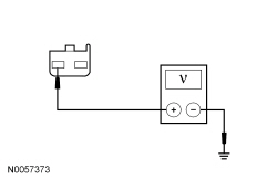
| H7 CHECK FOR VOLTAGE TO THE LIGHT SENSOR (NO DTCs) | |
| Yes
INSTALL a new light sensor. REFER to Light Sensor in this section. CLEAR the DTCs. REPEAT the self-test. No GO to H16 . |
| H8 CHECK THE WINDSHIELD WIPER MOTOR | |
| Yes
GO to H9 . No INSTALL a new windshield wiper motor. REFER to Section 501-16 . TEST the system for normal operation. |
| H9 CHECK THE WIPERS ON INPUT CIRCUIT FOR A SHORT TO GROUND | |
 | Yes
GO to H16 . No REPAIR circuit CRW01 (WH) for a short to ground. CLEAR the DTCs. REPEAT the self-test. |
| H10 CHECK FOR VOLTAGE TO THE LIGHT SENSOR (DTC B1791) | |
| Yes
GO to H13 . No GO to H11 . |
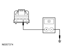
| H11 CHECK THE LIGHT SENSOR INPUT CIRCUIT FOR A SHORT TO VOLTAGE | |
| Yes
REPAIR circuit VLF14 (BU/BN) for a short to voltage. CLEAR the DTCs. REPEAT the self-test. No GO to H12 . |
| H12 CHECK THE LIGHT SENSOR INPUT CIRCUIT FOR AN OPEN | |
  | Yes
GO to H16 . No REPAIR circuit VLF14 (BU/BN) for an open. CLEAR the DTCs. REPEAT the self-test. |
| H13 CHECK FOR VOLTAGE TO THE LIGHT SENSOR USING THE CONNECTOR GROUND | |
  | Yes
INSTALL a new light sensor. REFER to Light Sensor in this section. CLEAR the DTCs. REPEAT the self-test. No REPAIR circuit GD116 (BK/VT) for an open. CLEAR the DTCs. REPEAT the self-test. |
| H14 CHECK FOR VOLTAGE TO THE LIGHT SENSOR (DTC B1793) | |
| Yes
INSTALL a new light sensor. REFER to Light Sensor in this section. CLEAR the DTCs. REPEAT the self-test. No GO to H15 . |
| H15 CHECK THE LIGHT SENSOR INPUT CIRCUIT FOR A SHORT TO GROUND | |
  | Yes
GO to H16 . No REPAIR circuit VLF14 (BU/BN) for a short to ground. CLEAR the DTCs. REPEAT the self-test. |
| H16 CHECK FOR CORRECT SJB OPERATION | |
| Yes
INSTALL a new SJB . REFER to Section 419-10 . TEST the system for normal operation. No The system is operating correctly at this time. The concern may have been caused by a loose or corroded connector. CLEAR the DTCs. REPEAT the self-test. |