
FLU77-4 or equivalent


105-R025D or equivalent
SECTION 417-01: Exterior Lighting
| 2014 Mustang Workshop Manual
|
DIAGNOSIS AND TESTING
| Procedure revision date: 01/07/2013
|
| Fluke 77-IV Digital Multimeter
FLU77-4 or equivalent |
| Vehicle Communication Module (VCM) and Integrated Diagnostic System (IDS) software with appropriate hardware, or equivalent scan tool
|
| Flex Probe Kit
105-R025D or equivalent |
Principles of Operation
NOTE: The Smart Junction Box (SJB) is also known as the Generic Electronic Module (GEM).
The SJB monitors the headlamp switch position by sending voltage signals on multiple circuits to the headlamp switch. There is one circuit for each headlamp switch position. At any given time, one of the signal circuits is switched to ground.
If the SJB does not detect any of the inputs to the headlamp switch is active (switched to ground) for 5 seconds, the SJB turns the parking lamps and headlamps on and keeps them on until the battery saver feature times out.
Additionally, if the SJB detects multiple headlamp switch input circuits short to ground, the SJB turns the parking lamps and headlamps on and keeps them on until the battery saver feature times out.
Refer to Exterior Lighting for information regarding the Battery Saver feature.
If the above situation occurs, the SJB cannot be ruled immediately as being at fault. This is normal behavior of the SJB design as it has detected a fault with the inputs from the headlamp switch.
Inspection and Verification
Visual Inspection Chart
| Mechanical | Electrical |
|---|---|
|
|
NOTE: Make sure to use the latest scan tool software release.
If the cause is not visually evident, connect the scan tool to the Data Link Connector (DLC).NOTE: The Vehicle Communication Module (VCM) LED prove-out confirms power and ground from the DLC are provided to the VCM .
If the scan tool does not communicate with the VCM :Symptom Chart
| Condition | Possible Sources | Action |
|---|---|---|
|
|
|
|
|
Pinpoint Tests
Pinpoint Test Q: One Or More Parking, Rear or License Plate Lamps Is Inoperative
Refer to Wiring Diagrams Cell 92 , Parking, Rear and License Lamps for schematic and connector information.
When the headlamp switch is placed in the PARKING LAMPS ON position, the Smart Junction Box (SJB) energizes the parking lamp relay coil (integrated into the SJB ). When the parking lamp relay is energized, voltage is routed to the rear and front parking lamps.
This pinpoint test is intended to diagnose the following:
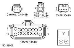
NOTICE: Use the correct probe adapter(s) when making measurements. Failure to use the correct probe adapter(s) may damage the connector.
| Test Step | Result / Action to Take | |||||||||||||||||||||||||||||||||||||||
|---|---|---|---|---|---|---|---|---|---|---|---|---|---|---|---|---|---|---|---|---|---|---|---|---|---|---|---|---|---|---|---|---|---|---|---|---|---|---|---|---|
| Q1 DETERMINE IF ALL THE PARKING LAMPS ARE INOPERATIVE | ||||||||||||||||||||||||||||||||||||||||
| Yes
PLACE the headlamp switch in the OFF position. VERIFY the SJB fuse 22 (15A) is OK. If OK, GO to Q6 . If not OK, REFER to the Wiring Diagrams Manual to identify the possible causes of the circuit short. No If all the front parking lamps are inoperative, GO to Q2 . If all the rear parking and license plate lamps are inoperative, GO to Q3 . For all others, GO to Q4 . | |||||||||||||||||||||||||||||||||||||||
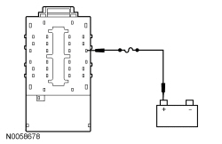
| Q2 CHECK THE SJB PARKING LAMP OUTPUT CIRCUIT FOR AN OPEN (FRONT LAMPS) | ||||||||||||||||||||||||||||||||||||||||
 | Yes
REMOVE the jumper wire. GO to Q7 . No REMOVE the jumper wire. REPAIR circuit CLS30 (VT/WH) for an open. TEST the system for normal operation. | |||||||||||||||||||||||||||||||||||||||
| Q3 CHECK THE SJB PARKING LAMP OUTPUT CIRCUIT FOR AN OPEN (REAR LAMPS) | ||||||||||||||||||||||||||||||||||||||||
 | Yes
REMOVE the jumper wire. GO to Q7 . No REMOVE the jumper wire. REPAIR circuit CLS30 (VT/WH) for an open. TEST the system for normal operation. | |||||||||||||||||||||||||||||||||||||||
| Q4 CHECK FOR VOLTAGE TO THE INOPERATIVE LAMP | ||||||||||||||||||||||||||||||||||||||||
 | Yes
GO to Q5 . No REPAIR circuit CLS30 (VT/WH) for an open. TEST the system for normal operation. | |||||||||||||||||||||||||||||||||||||||
| Q5 CHECK THE VOLTAGE TO THE INOPERATIVE LAMP USING THE CONNECTOR GROUND | ||||||||||||||||||||||||||||||||||||||||
| Yes
For any side marker or license plate lamp, INSTALL a new bulb holder. TEST the system for normal operation. For any front lamp, INSTALL a headlmap assembly. REFER to Headlamp Assembly . TEST the system for normal operation. For a rear lamp, GO to Q6 . No REPAIR the ground circuit in question for an open. TEST the system for normal operation. | |||||||||||||||||||||||||||||||||||||||
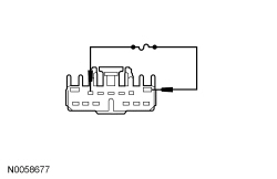
| Q6 CHECK THE REAR LAMP JUMPER HARNESS | ||||||||||||||||||||||||||||||||||||||||
| Yes
INSTALL a new LED lamp. TEST the system for normal operation. No REPAIR or INSTALL a new rear lamp jumper harness. TEST the system for normal operation. | |||||||||||||||||||||||||||||||||||||||
| Q7 CHECK FOR CORRECT SJB OPERATION | ||||||||||||||||||||||||||||||||||||||||
| Yes
INSTALL a new SJB . REFER to Section 419-10 . TEST the system for normal operation. No The system is operating correctly at this time. The concern may have been caused by a loose or corroded connector. |
Pinpoint Test R: The Parking, Rear Or License Plate Lamps Are On Continuously
Refer to Wiring Diagrams Cell 92 , Parking, Rear and License Lamps for schematic and connector information.
The Smart Junction Box (SJB) monitors the parking lamp request input from the headlamp switch. The SJB provides a ground for the parking lamp relay coil (integrated into the SJB ) when a request for the parking lamps is received. When the parking lamp relay is energized, voltage is routed to the rear and front parking lamps.
This pinpoint test is intended to diagnose the following:
NOTICE: Use the correct probe adapter(s) when making measurements. Failure to use the correct probe adapter(s) may damage the connector.
| Test Step | Result / Action to Take |
|---|---|
| R1 USE THE RECORDED DTCs FROM THE SJB SELF-TEST | |
| Yes
GO to R2 . No GO to R4 . |
| R2 CHECK FOR A VOLTAGE SIGNAL TO THE HEADLAMP SWITCH | |
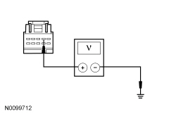 | Yes
INSTALL a new headlamp switch. REFER to Headlamp Switch in this section. CLEAR the DTCs. REPEAT the self-test. No GO to R3 . |
| R3 CHECK THE PARKING LAMP REQUEST INPUT CIRCUIT FOR A SHORT TO GROUND | |
 | Yes
GO to R6 . No REPAIR circuit CLS34 (GY) for a short to ground. CLEAR the DTCs. REPEAT the self-test. |
| R4 CHECK THE SJB PARKING LAMP OUTPUT CIRCUIT FOR A SHORT TO VOLTAGE (TO REAR LAMPS) | |
| Yes
REPAIR circuit CLS30 (VT/WH) for a short to voltage. TEST the system for normal operation. No GO to R5 . |
| R5 CHECK THE SJB PARKING LAMP OUTPUT CIRCUIT FOR A SHORT TO VOLTAGE (TO FRONT LAMPS) | |
| Yes
REPAIR circuit CLS30 (VT/WH) for a short to voltage. TEST the system for normal operation. No GO to R6 . |
| R6 CHECK FOR CORRECT SJB OPERATION | |
| Yes
INSTALL a new SJB . REFER to Section 419-10 . TEST the system for normal operation. No The system is operating correctly at this time. The concern may have been caused by a loose or corroded connector. CLEAR the DTCs. REPEAT the self-test. |