
FLU77-4 or equivalent

SECTION 307-01: Automatic Transaxle/Transmission — 6R80
| 2014 Mustang Workshop Manual
|
DIAGNOSIS AND TESTING
| Procedure revision date: 01/07/2013
|
 | Fluke 77-IV Digital Multimeter
FLU77-4 or equivalent |
 | Vehicle Communication Module (VCM) and Integrated Diagnostic System (IDS) software with appropriate hardware, or equivalent scan tool
|
When the electrical connector or solenoid body is disconnected, inspect the connector for terminal condition, corrosion and contamination. Also inspect the connector seal for damage. Clean, repair or install new components as required.
Power is routed through the Transmission Solenoid Power Control (TSPC) relay (inside the PCM) to all transmission solenoids. If the power circuit to the transmission solenoids or the TSPC relay fails open, then all solenoids are failed electrically OFF. CHECK for open, short to ground or the transmission connector disconnected. The TSPC relay will disable power to the transmission solenoids when certain transmission DTCs are set.
Shift Solenoid Pre-Diagnosis
Use the following shift solenoid operation information when carrying out Pinpoint Test A.
Solenoid Operation Chart
| Selector Lever Position | PCM Commanded Gear | Shift Solenoid | TCC NL | ||||
|---|---|---|---|---|---|---|---|
| SSA NL (1,2,3,4) | SSB NH (3,5,R) | SSC NL (CB 2,6) | SSD NH (CB L/R 4,5,6) | SSE NC | |||
| P | P | Off | On | Off | On | On | Off |
| R | R | Off | Off | Off | Off | On | Off |
| N | N | Off | On | Off | On a | On a | Off |
| D | 1 | On | On | Off | Off b | On | Off |
| 2 | On | On | On | On | Off | Off | |
| 3 | On | Off | Off | On | Off | Off | |
| 4 | On | On | Off | Off | Off | On/Off | |
| 5 | Off | Off | Off | Off | Off | On/Off | |
| 6 | Off | On | On | Off | Off | On/Off | |
| 3 | 3 | On | Off | Off | On | Off | Off |
| 2 | 2 | On | On | On | On | Off | Off |
| 1 | 1 | On | On | Off | Off | On | Off |
CB = Clutch brake
NC = Normally closed
NH = Normally high
NL = Normally low
Pinpoint Tests
Refer to Wiring Diagrams Cell 30 for schematic and connector information.
NOTE: Refer to all TSBs and On-Line Automotive Service Information System (OASIS) messages that pertain to the transmission concern and follow the procedure as described.
NOTE: The PCM connector C175T is used on vehicles equipped with a 5.0L (4V) engine and the PCM connector C1381T is used on vehicles equipped with a 3.7L engine.
NOTE: Refer to the Transmission Vehicle Harness Connector illustration within the Transmission Connector Layouts procedure in this section.
NOTE: Refer to the Transmission Leadframe Connector illustration within the Transmission Connector Layouts procedure in this section.
NOTE: If the scan tool is unable to access the transmission PIDs, refer to the Powertrain Control/Emissions Diagnosis (PC/ED) manual.
NOTE: Read and record all DTCs.
NOTE: Without a voltage signal return to the PCM, the Transmission Solenoid Power Control (TSPC) relay is commanded OFF. By using a fused jumper between a transmission solenoid control circuit and the signal return circuit, the TSPC relay circuit will supply power to the transmission solenoids when the ignition is cycled from OFF to ON. Do not use a solenoid control circuit that may be at fault, refer to Diagnostic Trouble Code (DTC) Charts in this section for a fault listing.
| Test Step | Result / Action to Take | ||||||||||||||||||||||||||||||||||||||||||||||||
|---|---|---|---|---|---|---|---|---|---|---|---|---|---|---|---|---|---|---|---|---|---|---|---|---|---|---|---|---|---|---|---|---|---|---|---|---|---|---|---|---|---|---|---|---|---|---|---|---|---|
| A1 CHECK THE SOLENOID POWER CIRCUIT FOR VOLTAGE | |||||||||||||||||||||||||||||||||||||||||||||||||
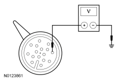 | Yes
GO to A4 . No GO to A2 . | ||||||||||||||||||||||||||||||||||||||||||||||||
| A2 CHECK THE SOLENOID POWER CIRCUIT FOR AN OPEN | |||||||||||||||||||||||||||||||||||||||||||||||||
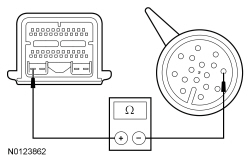  | Yes
GO to A3 . No REPAIR transmission vehicle harness circuit CET25 (BU/GN) for an open. CLEAR the DTC's. TEST the system for normal operation. If DTC P0657 returns, REPLACE the PCM. Section 303-14 . PROGRAM the PCM with the latest calibration level. PERFORM the Solenoid Body Strategy Data Download procedure. REFER to Solenoid Body Strategy in this section. TEST the system for normal operation. | ||||||||||||||||||||||||||||||||||||||||||||||||
| A3 CHECK THE SOLENOID POWER CIRCUIT FOR A SHORT TO GROUND | |||||||||||||||||||||||||||||||||||||||||||||||||
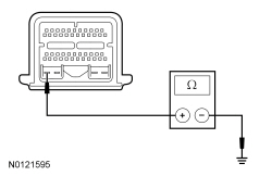  | Yes
GO to A4 . No REPAIR transmission vehicle harness circuit CET25 (BU/GN) for a short to ground. CLEAR the DTC's. TEST the system for normal operation. If DTC P0657 returns, REPLACE the PCM, Section 303-14 . PROGRAM the PCM with the latest calibration level. PERFORM the Solenoid Body Strategy Data Download procedure. REFER to Solenoid Body Strategy in this section. TEST the system for moral operation. | ||||||||||||||||||||||||||||||||||||||||||||||||
| A4 CHECK SOLENOID CONTROL CIRCUITS FOR AN OPEN | |||||||||||||||||||||||||||||||||||||||||||||||||
| Yes
GO to A5 . No REPAIR the transmission vehicle harness circuit which measured greater than 5 ohms. CLEAR the DTCs. TEST the system for normal operation. | ||||||||||||||||||||||||||||||||||||||||||||||||
| A5 CHECK SOLENOID CONTROL CIRCUITS FOR A SHORT TO GROUND | |||||||||||||||||||||||||||||||||||||||||||||||||
| Yes
GO to A6 . No REPAIR the transmission vehicle harness circuit which measured less than 10,000 ohms. CLEAR the DTCs. TEST the system for normal operation. | ||||||||||||||||||||||||||||||||||||||||||||||||
| A6 CHECK SOLENOID CONTROL CIRCUITS FOR A SHORT TO POWER | |||||||||||||||||||||||||||||||||||||||||||||||||
| Yes
REPAIR the transmission vehicle harness circuit shorted to power. CLEAR the DTCs. TEST the system for normal operation. No GO to A7 . | ||||||||||||||||||||||||||||||||||||||||||||||||
| A7 CHECK COMPONENT RESISTANCE | |||||||||||||||||||||||||||||||||||||||||||||||||
| Yes
REFER to Main Control to inspect for stuck valves or debris. If no problems are found, INSTALL suspected solonoid. REFER to Shift Solenoids (SS) . CLEAR the DTCs. TEST the system for normal operation. No GO to A8 . | ||||||||||||||||||||||||||||||||||||||||||||||||
| A8 CHECK SOLENOID RESISTANCE | |||||||||||||||||||||||||||||||||||||||||||||||||
| Yes
INSTALL a new molded leadframe, REFER to Shift Solenoids (SS) in this section. CLEAR the DTCs. TEST the system for normal operation. No REPLACE the suspected solenoid which failed the resistance check. REFER to Shift Solenoids (SS) in this section. CLEAR the transmission adaptive tables and perform the adaptive drive cycle. REFER to Shift Point Road Test in this section. TEST the system for normal operation. |
NOTE: Refer to the Transmission Vehicle Harness Connector illustration within the Transmission Connector Layouts procedure in this section.
NOTE: Refer to the Transmission Leadframe Connector illustration within the Transmission Connector Layouts procedure in this section.
NOTE: If the scan tool is unable to access the transmission PIDs, refer to the Powertrain Control/Emissions Diagnosis (PC/ED) manual.
NOTE: Read and record all DTCs.
| Test Step | Result / Action to Take | ||||||||||||||||||||||||||||||
|---|---|---|---|---|---|---|---|---|---|---|---|---|---|---|---|---|---|---|---|---|---|---|---|---|---|---|---|---|---|---|---|
| B1 CHECK TFT SENSOR SIGNAL INPUT | |||||||||||||||||||||||||||||||
| Yes
GO to B2 . No REPAIR vehicle harness circuit VET27 (BN/YE) for a short to ground. CLEAR the DTCs. TEST the system for normal operation. | ||||||||||||||||||||||||||||||
| B2 CHECK TFT SENSOR SIGNAL CIRCUIT | |||||||||||||||||||||||||||||||
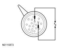 | Yes
GO to B4 . No GO to B3 . | ||||||||||||||||||||||||||||||
| B3 CHECK TFT SENSOR SIGNAL VOLTAGE | |||||||||||||||||||||||||||||||
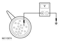 | Yes
GO to B4 . No INSPECT and REPAIR circuit VET27 (BN/YE) for an open. If an open circuit is not found, REPLACE the PCM, REFER to Section 303-14 . PROGRAM the PCM with the latest calibration level. PERFORM the Solenoid Body Strategy Data Download procedure. REFER to Solenoid Body Strategy in this section. TEST the system for normal operation. | ||||||||||||||||||||||||||||||
| B4 CHECK TFT SENSOR RESISTANCE | |||||||||||||||||||||||||||||||
TRANSMISSION FLUID TEMPERATURE (TFT)
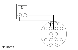 | Yes
REFER to Diagnosis By Symptom in this section to diagnose an overheating concern. No INSPECT and CLEAN the TFT sensor on the molded leadframe for metallic contamination. INSTALL a new molded leadframe if no debris was found, REFER to Shift Solenoids (SS) in this section. CLEAR the DTCs. TEST the system for normal operation. |
NOTE: Refer to the Transmission Vehicle Harness Connector illustration within the Transmission Connector Layouts procedure in this section.
NOTE: Refer to the Transmission Leadframe Connector illustration within the Transmission Connector Layouts procedure in this section.
NOTE: If the scan tool is unable to access the transmission PIDs, refer to the Powertrain Control/Emissions Diagnosis (PC/ED) manual.
NOTE: Read and record all DTCs.
| Test Step | Result / Action to Take | ||||||||||||||||
|---|---|---|---|---|---|---|---|---|---|---|---|---|---|---|---|---|---|
| C1 VERIFY DTCs | |||||||||||||||||
| Yes
GO to C3 . No GO to C2 . | ||||||||||||||||
| C2 VERIFY SELECTOR LEVER CABLE/LINKAGE ADJUSTMENT | |||||||||||||||||
| Yes
GO to C3 . No ADJUST the selector lever cable. REFER to Section 307-05 . | ||||||||||||||||
| C3 CHECK TR SENSOR ELECTRICAL OPERATION | |||||||||||||||||
| Yes
The problem is not in the TR sensor system. REFER to Diagnosis By Symptom in this section for further diagnosis. No GO to C4 . | ||||||||||||||||
| C4 CHECK TR SENSOR VPWR CIRCUIT FOR POWER | |||||||||||||||||
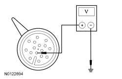 | Yes
INSPECT and REPAIR circuit LE111 (VT/GN) for an open. If an open is not found, REPLACE the PCM, REFER to Section 303-14 . PROGRAM the PCM with the latest calibration level. PERFORM the Solenoid Body Strategy Data Download procedure. REFER to Solenoid Body Strategy in this section. TEST the system for normal operation. No GO to C5 . | ||||||||||||||||
| C5 CHECK TR SENSOR SIGNAL CIRCUIT | |||||||||||||||||
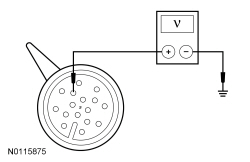 | Yes
GO to C6 . No INSPECT and REPAIR circuit CET60 (WH/GN) for an open. If an open circuit is not found, REPLACE the PCM, REFER to Section 303-14 . PROGRAM the PCM with the latest calibration level. PERFORM the Solenoid Body Strategy Data Download procedure. REFER to Solenoid Body Strategy in this section. TEST the system for normal operation. | ||||||||||||||||
| C6 CHECK TR SENSOR GROUND CIRCUIT | |||||||||||||||||
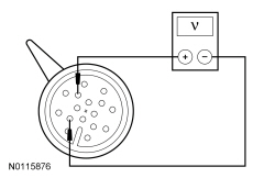 | Yes
GO to C7 . No REPAIR circuit RET24 (BN/BU) for an open. CLEAR the DTCs. TEST the system for normal operation. | ||||||||||||||||
| C7 CHECK TR SENSOR POWER CIRCUIT FOR A SHORT TO GROUND | |||||||||||||||||
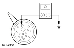 | Yes
GO to C8 . No REPAIR circuit CET60 (WH/GN) for a short to ground. CLEAR the DTCs. TEST the system for normal operation. | ||||||||||||||||
| C8 CHECK TR SENSOR CIRCUITS FOR A SHORT TO POWER | |||||||||||||||||
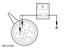 | Yes
REPAIR the circuit that is shorted to power. CLEAR the DTCs. TEST the system for normal operation. No GO to C9 . | ||||||||||||||||
| C9 CHECK TR SENSOR TO MANUAL VALVE | |||||||||||||||||
| Yes
REPLACE the PCM, REFER to Section 303-14 . PROGRAM the PCM with the latest calibration level. PERFORM the Solenoid Body Strategy Data Download procedure. REFER to Solenoid Body Strategy in this section. TEST the system for normal operation. No CONNECT the TR sensor to the manual valve, REFER to Transmission in this section. Or CLEAN all debris from the molded leadframe. RUN the Key ON Engine OFF (KOEO) self-test. If DTCs return, REPLACE the molded leadframe, REFER to Shift Solenoids (SS) in this section. |
NOTE: Refer to the Transmission Vehicle Harness Connector illustration within the Transmission Connector Layouts procedure in this section.
NOTE: Refer to the Transmission Leadframe Connector illustration within the Transmission Connector Layouts procedure in this section.
NOTE: If the scan tool is unable to access the transmission PIDs, refer to the Powertrain Control/Emissions Diagnosis (PC/ED) manual.
NOTE: Always drive the vehicle in a safe manner according to driving conditions and obey all traffic laws.
NOTE: Read and record all DTCs.
NOTE: If DTCs P0706, P0707, P0708, P0709, P1702 and/or P1921 are set, diagnose those DTCs first.
| Test Step | Result / Action to Take |
|---|---|
| D1 DRIVE CYCLE TEST | |
| Yes
REFER to Diagnosis By Symptom in this section for further diagnosis. No GO to D2 . |
| D2 CHECK TSS SENSOR SIGNAL CIRCUIT FOR AN OPEN | |
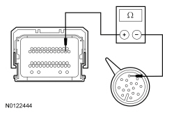 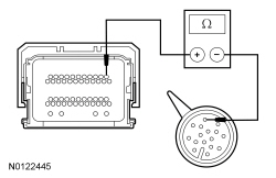 | Yes
GO to D3 . No REPAIR circuit VET33 (WH/OG) for an open. CLEAR the DTCs. TEST the system for normal operation. |
| D3 CHECK TSS SENSOR SIGNAL CIRCUIT FOR A SHORT TO GROUND | |
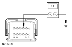 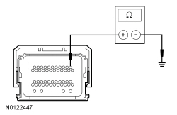 | Yes
GO to D4 . No REPAIR circuit VET33 (WH/OG) for a short to ground. CLEAR the DTCs. TEST the system for normal operation. |
| D4 CHECK TSS SENSOR SIGNAL CIRCUIT FOR A SHORT TO POWER | |
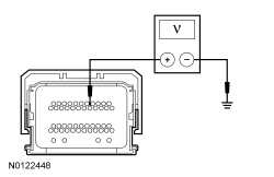 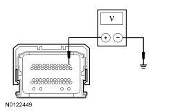 | Yes
REPAIR circuit VET33 (WH/OG) for a short to voltage. CLEAR the DTCs. TEST the system for normal operation. No GO to D5 . |
| D5 CHECK TSS SENSOR SIGNAL CIRCUIT FOR POWER | |
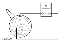 | Yes
INSPECT and REPAIR circuit RET24 (BN/BU) for an open. If an open is not found, REPLACE the PCM, REFER to Section 303-14 . PROGRAM the PCM with the latest calibration level. PERFORM the Solenoid Body Strategy Data Download procedure. REFER to Solenoid Body Strategy in this section. TEST the system for normal operation. No GO to D6 . |
| D6 CHECK TSS SENSOR VPWR CIRCUIT FOR POWER | |
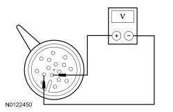 | Yes
INSPECT and REPAIR circuit LE111 (VT/GN) for an open. If an open is not found, REPLACE the PCM, REFER to Section 303-14 . PROGRAM the PCM with the latest calibration level. PERFORM the Solenoid Body Strategy Data Download procedure. REFER to Solenoid Body Strategy in this section. TEST the system for normal operation. No REPLACE the molded leadframe, REFER to Shift Solenoids (SS) in this section. CLEAR the DTCs. TEST the system for normal operation. |
NOTE: Refer to the Transmission Vehicle Harness Connector illustration within the Transmission Connector Layouts procedure in this section.
NOTE: Refer to the Transmission Leadframe Connector illustration within the Transmission Connector Layouts procedure in this section.
NOTE: If the scan tool is unable to access the transmission PIDs, refer to the Powertrain Control/Emissions Diagnosis (PC/ED) manual.
NOTE: Always drive the vehicle in a safe manner according to driving conditions and obey all traffic laws.
NOTE: Read and record all DTCs.
NOTE: If DTCs P0706, P0707, P0708, P0709, P1702 and/or P1921 are set, diagnose those DTCs first.
| Test Step | Result / Action to Take |
|---|---|
| E1 DRIVE CYCLE TEST | |
| Yes
REFER to Diagnosis By Symptom in this section for further diagnosis. No GO to E2 . |
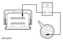
| E2 CHECK OSS SENSOR SIGNAL CIRCUIT FOR AN OPEN | |
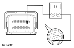  | Yes
GO to E3 . No REPAIR circuit VET26 (BN/GN) for an open. CLEAR the DTCs. TEST the system for normal operation. |
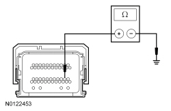
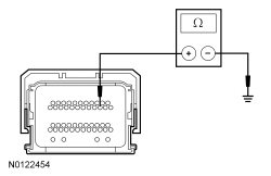
| E3 CHECK OSS SENSOR SIGNAL CIRCUIT FOR A SHORT TO GROUND | |
  | Yes
GO to E4 . No REPAIR circuit VET26 (BN/GN) for a short to ground. CLEAR the DTCs. TEST the system for normal operation. |
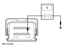
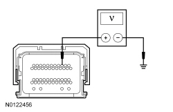
| E4 CHECK OSS SENSOR SIGNAL CIRCUIT FOR A SHORT TO POWER | |
  | Yes
REPAIR circuit VET26 (BN/GN) for a short to voltage. CLEAR the DTCs. TEST the system for normal operation. No GO to E5 . |
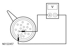
| E5 CHECK OSS SENSOR SIGNAL CIRCUIT FOR POWER | |
 | Yes
INSPECT and REPAIR circuit RET24 (BN/BU) for an open. If an open is not found, REPLACE the PCM, REFER to Section 303-14 . PROGRAM the PCM with the latest calibration level. PERFORM the Solenoid Body Strategy Data Download procedure. REFER to Solenoid Body Strategy in this section. TEST the system for normal operation. No GO to E6 . |
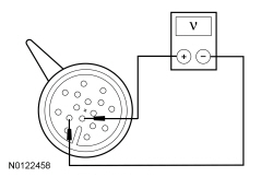
| E6 CHECK OSS SENSOR VPWR CIRCUIT FOR POWER | |
 | Yes
INSPECT and REPAIR circuit LE111 (VT/GN) for an open. If an open is not found, REPLACE the PCM, REFER to Section 303-14 . PROGRAM the PCM with the latest calibration level. PERFORM the Solenoid Body Strategy Data Download procedure. REFER to Solenoid Body Strategy in this section. TEST the system for normal operation. No REPLACE the molded leadframe, REFER to Shift Solenoids (SS) in this section. CLEAR the DTCs. TEST the system for normal operation |