SECTION 501-20B: Supplemental Restraint System
| 2014 Mustang Workshop Manual
|
DIAGNOSIS AND TESTING
| Procedure revision date: 04/24/2013
|
Airbag and Safety Belt Pretensioner Supplemental Restraint System (SRS)
Principles of Operation
The Restraints Control Module (RCM) continuously receives/monitors all inputs from the following Supplemental Restraint System (SRS) components:
- Front impact severity sensor (frontal restraints sensor)
- First row side impact sensor (left/right side restraints sensor 1)
- Safety belt buckle switches (driver and passenger)
- Driver seat track position sensor
- Occupant Classification System Module (OCSM)
If the
detects sudden vehicle deceleration and/or lateral deceleration based on the information received from all sensors and switches and determines that deployment is required, the
sends voltage and current to deploy the appropriate
components.
During a frontal or side crash, the
may deploy the following
components, based on crash severity and sensor input.
- Safety belt retractor pretensioner(s)
- Seat side air bag(s)
- Driver/passenger dual-stage air bag (one or both stages)
The fact that the safety belt retractor pretensioner(s) or air bags did not activate for both front seat occupants in a crash does not mean that something is wrong with the system.
The
performs a self-test of the complete
during each startup. If a
fault exists, the air bag warning indicator will illuminate and remain illuminated for the rest of the ignition cycle. In addition to the self-test at start up, the
continuously monitors all of its
components and circuitry for correct operation.
Air Bag Warning Indicator
The air bag warning indicator:
- located in the Instrument Panel Cluster (IPC) will prove out by lighting for 6 seconds and then turn off.
- will flash and/or illuminate based on the message the
receives from the
.
- will illuminate if the
does not receive a message from the
.
Air Bag Module Second Stage Deployment Check
Because the driver and passenger front air bags each have 2 deployment stages, it is possible that Stage 1 has deployed and Stage 2 has not.
If a front air bag module has deployed, it is
mandatory
that the front air bag module be remotely deployed using the appropriate air bag disposal procedure.
- For information on driver air bag module and/or passenger air bag module remote deployment, refer to
Pyrotechnic Device Disposal
in this section.
Clockspring
The clockspring:
- allows for continuous electrical connections between the driver air bag module and the
when the steering wheel is turned.
Driver Air Bag Module
The driver air bag module:
- is a dual-stage air bag, upon receiving a flow of current from the
, deploying at 1 of 2 different rates depending upon vehicle impact severity and sensor input.
Event Notification Signal
In the event of a crash, the
provides an event notification signal to the fuel pump driver module(s) to disable the fuel system.
The
does not monitor the event notification signal circuit for faults and will not set a DTC if a fault occurs.
High Speed Controller Area Network (HS-CAN)
This vehicle utilizes a communication system called a High Speed Controller Area Network (HS-CAN). The
communicates with various modules for required information about the vehicle. Refer to
Section 418-00
for information about the
.
Impact Sensor
The
uses 3 satellite sensors in addition to the
. The
is mounted to the center tunnel beneath the console. The front impact severity sensor (frontal restraint sensor) is located in the front of the vehicle, behind the grille, mounted on the radiator support. The side impact sensors are mounted in each of the doors, behind the trim panel. Mounting orientation is critical for correct operation of all impact sensors.
Occupant Classification System (OCS)
The Occupant Classification System (OCS) is found only on the front passenger seat. The front passenger seat
is comprised of a silicone gel-filled bladder mounted between the seat cushion foam and pan. An integrated
with pressure sensor is attached to the bladder by a flexible hose. The integrated
with pressure sensor is mounted to the seat frame. Pressure is applied to the
bladder when weight of any occupant or object in the front passenger seat is present. The pressure is then transferred through a tube and is sensed by the
pressure sensor. The
communicates front passenger classification information to the
via the
. The
uses this information when determining if the passenger air bag module is to be deployed in the event of a deployable crash. The
also uses this information for Passenger Air Bag Deactivation (PAD) indicator illumination strategy.
The
monitors the
for faults.
The
is also used for operation of the passenger Belt Minder®. For information on the passenger Belt Minder® feature, refer to
Section 501-20A
. To deactivate or reactivate the passenger Belt Minder® feature, refer to
Section 413-01
or the Owner's Literature.
Belt Tension Sensor (BTS)
The Belt Tension Sensor (BTS):
- is a 3-wire Hall-effect sensor located at the safety belt anchor point and is part of the front passenger safety belt and retractor assembly.
- is used in conjunction with the
.
The
is used by the
to identify the presence of a child safety seat on the front passenger seat. The
senses the tension on the safety belt assembly then provides an output to the
, indicating that the safety belt assembly is cinched. After sensing the weight applied to the seat by the occupant and using the
input, the
determines how the occupant should be classified and communicates the information to the
. If the occupant is classified as a child, the
then automatically deactivates the passenger air bag module and illuminates the
indicator.
Passenger Air Bag Deactivation (PAD) Indicator
The Restraints Control Module (RCM) controls the state of the Passenger Air Bag Deactivation (PAD) indicator through a direct hard-wire connection, based on information provided by the
system. An exemption to this is when the front passenger seat is determined to be empty, and therefore indication of a deactivated passenger air bag module is not necessary. In all other cases, the
indicator is off when the passenger air bag module is enabled.
When the ignition is ON, the
briefly activates the
indicator to prove out the indicator function and verify to the front occupants correct functional operation of the
indicator.
The following table indicates the passenger air bag status and the
indicator status based on the size of the front passenger occupant.
Passenger Air Bag and Passenger Air Bag Deactivation (PAD) Indicator Status
| Occupant Size
| Passenger Safety Belt Buckle Status
| Passenger Air Bag Status
| Indicator
|
|---|
| None
| Unbuckled
| Disabled
| Unlit
|
| None
| Buckled
| Disabled
| Lit
|
| Small
| Buckled/ Unbuckled
| Disabled
| Lit
|
| Large
| Buckled/ Unbuckled
| Enabled
| Unlit
|
Passenger Air Bag Module
The passenger air bag module:
- is a dual-stage air bag, deploying at 1 of 2 different rates depending upon vehicle impact severity and sensor input.
Restraints Control Module (RCM)
 WARNING: If a vehicle has been in a crash, inspect the restraints control module (RCM) and the impact sensor (if equipped) mounting areas for deformation. If damaged, restore the mounting areas to the original production configuration. A new RCM and sensors must be installed whether or not the airbags have deployed. Failure to follow these instructions may result in serious personal injury or death in a crash.
NOTE:
Carrying out Programmable Module Installation (PMI) will not enable the 911 assist option that is disabled.
The
carries out the following functions:
- Activates the driver, passenger and/or side air bag modules depending upon vehicle impact severity and the sensor inputs.
- Activates the driver and passenger retractor pretensioner(s) to control the tension of the driver and passenger safety belts in the event of a deployable crash
- Monitors the
for faults
- Sends a message to the
to illuminate the air bag warning indicator if a fault is detected
- Communicates through the Data Link Connector (DLC) the current or historical DTCs
The
monitors the
for possible faults. If a fault is detected, the
will request the
to illuminate the air bag warning indicator. When the ignition is turned OFF and then ON, the
will prove out the air bag warning indicator by lighting for 6 seconds. If no faults are detected by the
, the
will turn the air bag warning indicator off and it will remain off. If the
detects a fault, it will send a message to the
to turn the air bag warning indicator on and it will remain on for the rest of the ignition cycle. If the
requests illumination of the air bag warning indicator and the air bag warning indicator does not function, the
will automatically activate an audible chime. The chime is a series of 5 sets of 5 tone bursts. If the chime is heard, the
and the air bag warning indicator require repair.
The
includes a backup power supply. This feature provides sufficient backup power to deploy the air bags in the event that the ignition circuit is lost or damaged during impact. The backup power supply will deplete its stored energy approximately one minute after power and/or ground has been removed from the
.
Safety Belt Buckle Switches
The safety belt buckles are comprised of integrated circuits called Hall-effect switches. The safety belt buckle switches indicate to the
whether the safety belts are buckled or unbuckled.
The
supplies current to the safety belt buckle switch. Current flows through the switch, buckled or unbuckled to ground. The
will sense the difference in this current draw, approximately 6 mA (unbuckled) or 15 mA (buckled), and use this information in determining the deployment rate of the dual-stage driver and passenger air bag modules. If the
detects current out of this range, it will set a DTC.
The
also communicates the driver safety belt buckle switch status to the
, which monitors the information to control the safety belt warning indicator. For information on the safety belt warning indicator, refer to
Section 413-01
.
Safety Belt Retractor Pretensioner
Safety belt retractor pretensioners are pyrotechnic devices integrated to the safety belt retractor assemblies. Safety belt retractor pretensioners control the tension of the driver and passenger safety belts in the event of a deployable crash.
Seat Track Position Sensors
The seat track position sensors are comprised of integrated circuits called Hall-effect switches. The seat track position sensors indicate to the
the position of the driver and passenger seat. The
uses this information in determining the deployment rate of the dual-stage air bag modules.
Secondary Air Bag Warning (Chime)
The secondary air bag warning chime is an audible chime located in and controlled by the
. If a fault is detected with the air bag warning indicator, a DTC will be stored in memory of the
. Upon receiving the message from the
that a
fault has been detected, the
will sound the secondary air bag warning chime in a pattern of 5 sets of 5 beeps.
Seat Side Air Bag Module
The side air bag module is mounted in the seat backrest and will deploy upon receiving a flow of current from the
.
Fault PIDs
There are 2 types of fault PIDs that can be reported by the
. The first type, considered conventional, has only one level of fault reporting and identifies a specific concern for a given component and points to a particular diagnostic path, example: DTC B1317 (Battery Voltage High).
The second type uses a process within the software of the controller that maps the byte and bit to name a specific device and fault condition. This process is called bit-mapping and is referred to as fault PIDs in the diagnosis of the vehicle. This type does not identify the specific concern or component on the first level of fault reporting, example: DTC B2909 (
Fault). DTC B2909 can have up to 3 specific on-demand fault PIDs (areas of concern) associated with this DTC.
Those associated fault PIDs are an extension of the information provided by the DTC and are identified by the same DTC number. A scan tool must be used to view DTCs and their fault PIDs. Once a scan tool has retrieved a DTC, use the scan tool to view the fault PIDs. In the diagnostic path, other types of PIDs are sometimes used to determine the root cause (example: resistance or voltage PIDs).
When viewing fault PIDs, the scan tool can display the PIDs associated with that DTC, including the status or state that exists (on-demand [active] DTC) or existed (continuous memory [historic] DTC). Refer to the manufacturer instructions for the scan tool being used on how to view fault PIDs.
NOTE:
Do not mistake status information displayed with DTCs for fault PID information. Fault PIDs are only retrieved in the DataLogger function of the scan tool.
While the
does not
utilize fault PIDs for this vehicle, the
has fault PIDs for certain faults.
Prove Out Procedure
Turn ignition from OFF to the ON position and monitor the air bag warning indicator with all
components connected. The
will illuminate the air bag warning indicator continuously for approximately 6 seconds and then turn off. If a
fault is present, the air bag warning indicator will:
- fail to light.
- remain lit continuously.
- flash.
The air bag warning indicator may not illuminate to indicate a fault is present until approximately 30 seconds after the ignition has been turned from the OFF to the ON position. This is the time required for the
to complete the testing of the
. If the air bag warning indicator is inoperative and a
fault is detected, a chime will sound in a pattern of 5 sets of 5 beeps. If this occurs, the air bag warning indicator will need to be repaired before diagnosis can continue.
Inspection and Verification
- Verify the customer concern by checking the air bag warning indicator in the
. Refer to Prove Out the System in this section.
- Visually inspect for obvious signs of mechanical or electrical damage. Do not disconnect electrical connectors until directed to do so within the pinpoint test.
Visual Inspection Chart
| Mechanical
| Electrical
|
|---|
- Damaged Restraints Control Module (RCM) or loose mounting
- Damaged front impact severity sensor(s) or loose mounting
- Damaged side impact sensor(s) or loose mounting
- Damaged or disconnected Passenger Air Bag Deactivation (PAD) indicator
- Damaged or disconnected Occupant Classification System Module (OCSM) or loose mounting
| - Open Smart Junction Box (SJB) fuse 31 (10A) (
) or fuse 46 (7.5A) (
and
indicator)
- Damaged wiring harness
- Loose, damaged or corroded connectors
- Circuitry open/shorted
- Damaged shorting bars
- Loose, damaged or pinched passenger seat wire harness
|
- If an obvious cause for an observed or reported concern is found, correct the cause (if possible) before proceeding to the next step.
NOTE:
Make sure to use the latest scan tool software release.
If the cause is not visually evident, connect the scan tool to the
.
NOTE:
The Vehicle Communication Module (VCM) LED prove out confirms power and ground from the
are provided to the
.
If the scan tool does not communicate with the
:
- check the
connection to the vehicle.
- check the scan tool connection to the
.
- refer to
Section 418-00
, No Power To The Scan Tool, to diagnose no power to the scan tool.
- If the scan tool does not communicate with the vehicle:
- verify the ignition is ON.
- verify the scan tool operation with a known good vehicle.
- Carry out the network test.
- If the scan tool responds with no communication for one or more modules, refer to
Section 418-00
.
- If the network test passes, retrieve and record on-demand and Continuous Memory Diagnostic Trouble Codes (CMDTCs) from the
and
.
- If the DTCs retrieved are related to the concern, go to the
DTC chart or the
DTC chart in this section.
- If no DTCs related to the concern are retrieved, GO to
Symptom Chart
.
DTC Charts
The DTCs can be retrieved from the
and the
with a scan tool via the
.
Restraints Control Module (RCM) DTC Chart
NOTE:
Always make sure the correct Supplemental Restraint System (SRS) component is being installed. Parts released for other vehicles may not be compatible even if they appear physically similar. Check the part number listed in the Ford Catalog Advantage™ or equivalent to make sure the correct component is being installed. If an incorrect
component is installed, DTCs may set.
NOTE:
This module utilizes a 5-character DTC followed by a 2-character failure type code. The failure type code provides information about specific fault conditions such as opens or shorts to ground. Continuous Memory Diagnostic Trouble Codes (CMDTCs) have an additional 2-character DTC status code suffix to assist in determining DTC history.
| DTC
| Description
| Action To Take
|
|---|
| B0001:11
| Driver Frontal Stage 1 Deployment Control: Circuit Short to Ground
| GO to Pinpoint Test B
.
|
| B0001:12
| Driver Frontal Stage 1 Deployment Control: Circuit Short to Battery
| GO to Pinpoint Test B
.
|
| B0001:13
| Driver Frontal Stage 1 Deployment Control: Circuit Open
| GO to Pinpoint Test B
.
|
| B0001:1A
| Driver Frontal Stage 1 Deployment Control: Circuit Resistance Below Threshold
| GO to Pinpoint Test B
.
|
| B0001:2B
| Driver Frontal Stage 1 Deployment Control: Signal Cross Coupled
| GO to Pinpoint Test S
.
|
| B0001:4A
| Driver Frontal Stage 1 Deployment Control: Incorrect Component Installed
| GO to Pinpoint Test T
.
|
| B0002:11
| Driver Frontal Stage 2 Deployment Control: Circuit Short to Ground
| GO to Pinpoint Test C
.
|
| B0002:12
| Driver Frontal Stage 2 Deployment Control: Circuit Short to Battery
| GO to Pinpoint Test C
.
|
| B0002:13
| Driver Frontal Stage 2 Deployment Control: Circuit Open
| GO to Pinpoint Test C
.
|
| B0002:1A
| Driver Frontal Stage 2 Deployment Control: Circuit Resistance Below Threshold
| GO to Pinpoint Test C
.
|
| B0002:2B
| Driver Frontal Stage 2 Deployment Control: Signal Cross Coupled
| GO to Pinpoint Test S
.
|
| B0002:4A
| Driver Frontal Stage 2 Deployment Control: Incorrect Component Installed
| GO to Pinpoint Test T
.
|
| B0010:11
| Passenger Frontal Stage 1 Deployment Control: Circuit Short to Ground
| GO to Pinpoint Test D
.
|
| B0010:12
| Passenger Frontal Stage 1 Deployment Control: Circuit Short to Battery
| GO to Pinpoint Test D
.
|
| B0010:13
| Passenger Frontal Stage 1 Deployment Control: Circuit Open
| GO to Pinpoint Test D
.
|
| B0010:1A
| Passenger Frontal Stage 1 Deployment Control: Circuit Resistance Below Threshold
| GO to Pinpoint Test D
.
|
| B0010:2B
| Passenger Frontal Stage 1 Deployment Control: Signal Cross Coupled
| GO to Pinpoint Test S
.
|
| B0010:4A
| Passenger Frontal Stage 1 Deployment Control: Incorrect Component Installed
| GO to Pinpoint Test T
.
|
| B0011:11
| Passenger Frontal Stage 2 Deployment Control: Circuit Short to Ground
| GO to Pinpoint Test E
.
|
| B0011:12
| Passenger Frontal Stage 2 Deployment Control: Circuit Short to Battery
| GO to Pinpoint Test E
.
|
| B0011:13
| Passenger Frontal Stage 2 Deployment Control: Circuit Open
| GO to Pinpoint Test E
.
|
| B0011:1A
| Passenger Frontal Stage 2 Deployment Control: Circuit Resistance Below Threshold
| GO to Pinpoint Test E
.
|
| B0011:2B
| Passenger Frontal Stage 2 Deployment Control: Signal Cross Coupled
| GO to Pinpoint Test S
.
|
| B0011:4A
| Passenger Frontal Stage 2 Deployment Control: Incorrect Component Installed
| GO to Pinpoint Test T
.
|
| B0020:11
| Left Side Airbag Deployment Control: Circuit Short to Ground
| GO to Pinpoint Test F
.
|
| B0020:12
| Left Side Airbag Deployment Control: Circuit Short to Battery
| GO to Pinpoint Test F
.
|
| B0020:13
| Left Side Airbag Deployment Control: Circuit Open
| GO to Pinpoint Test F
.
|
| B0020:1A
| Left Side Airbag Deployment Control: Circuit Resistance Below Threshold
| GO to Pinpoint Test F
.
|
| B0020:2B
| Left Side Airbag Deployment Control: Signal Cross Coupled
| GO to Pinpoint Test S
.
|
| B0020:4A
| Left Side Airbag Deployment Control: Incorrect Component Installed
| GO to Pinpoint Test T
.
|
| B0028:11
| Right Side Airbag Deployment Control: Circuit Short to Ground
| GO to Pinpoint Test G
.
|
| B0028:12
| Right Side Airbag Deployment Control: Circuit Short to Battery
| GO to Pinpoint Test G
.
|
| B0028:13
| Right Side Airbag Deployment Control: Circuit Open
| GO to Pinpoint Test G
.
|
| B0028:1A
| Right Side Airbag Deployment Control: Circuit Resistance Below Threshold
| GO to Pinpoint Test G
.
|
| B0028:2B
| Right Side Airbag Deployment Control: Signal Cross Coupled
| GO to Pinpoint Test S
.
|
| B0028:4A
| Right Side Airbag Deployment Control: Incorrect Component Installed
| GO to Pinpoint Test T
.
|
| B0050:11
| Driver Seatbelt Sensor: Circuit Short to Ground
| GO to Pinpoint Test H
.
|
| B0050:12
| Driver Seatbelt Sensor: Circuit Short to Battery
| GO to Pinpoint Test H
.
|
| B0050:13
| Driver Seatbelt Sensor: Circuit Open
| GO to Pinpoint Test H
.
|
| B0050:1D
| Driver Seatbelt Sensor: Circuit Current Out of Range
| GO to Pinpoint Test H
.
|
| B0050:2B
| Driver Seatbelt Sensor: Signal Cross Coupled
| GO to Pinpoint Test S
.
|
| B0050:4A
| Driver Seatbelt Sensor: Incorrect Component Installed
| GO to Pinpoint Test T
.
|
| B0052:11
| Passenger Seatbelt Sensor: Circuit Short to Ground
| GO to Pinpoint Test I
.
|
| B0052:12
| Passenger Seatbelt Sensor: Circuit Short to Battery
| GO to Pinpoint Test I
.
|
| B0052:13
| Passenger Seatbelt Sensor: Circuit Open
| GO to Pinpoint Test I
.
|
| B0052:1D
| Passenger Seatbelt Sensor: Circuit Current Out of Range
| GO to Pinpoint Test I
.
|
| B0052:2B
| Passenger Seatbelt Sensor: Signal Cross Coupled
| GO to Pinpoint Test S
.
|
| B0052:4A
| Passenger Seatbelt Sensor: Incorrect Component Installed
| GO to Pinpoint Test T
.
|
| B0090:11
| Left Frontal Restraints Sensor: Circuit Short to Ground
| GO to Pinpoint Test J
.
|
| B0090:4A
| Left Frontal Restraints Sensor: Incorrect Component Installed
| GO to Pinpoint Test T
.
|
| B0090:81
| Left Frontal Restraints Sensor: Invalid Serial Data Received
| INSTALL a new front impact severity sensor. REFER to
Front Impact Severity Sensor
in this section.
|
| B0090:93
| Left Frontal Restraints Sensor: No Operation
| GO to Pinpoint Test J
.
|
| B0090:96
| Left Frontal Restraints Sensor: Component Internal Failure
| INSTALL a new front impact severity sensor. REFER to
Front Impact Severity Sensor
in this section.
|
| B0091:11
| Left Side Restraints Sensor 1: Circuit Short to Ground
| GO to Pinpoint Test K
.
|
| B0091:4A
| Left Side Restraints Sensor 1: Incorrect Component Installed
| GO to Pinpoint Test T
.
|
| B0091:81
| Left Side Restraints Sensor 1: Invalid Serial Data Received
| INSTALL a new driver side impact sensor. REFER to
Side Impact Sensor
in this section.
|
| B0091:93
| Left Side Restraints Sensor 1: No Operation
| GO to Pinpoint Test K
.
|
| B0091:96
| Left Side Restraints Sensor 1: Component Internal Failure
| INSTALL a new driver side impact sensor. REFER to
Side Impact Sensor
in this section.
|
| B0095:11
| Right Frontal Restraints Sensor: Circuit Short to Ground
| NOTE:
This vehicle is not equipped with this component. This DTC indicates the
is incorrectly configured or the incorrect
is installed to the vehicle.
INSTALL a new
and CARRY OUT Programmable Module Installation (PMI). Use as-built data when CARRYING OUT
. REFER to
Restraints Control Module (RCM)
in this section.
|
| B0095:4A
| Right Frontal Restraints Sensor: Incorrect Component Installed
| GO to Pinpoint Test T
.
|
| B0095:81
| Right Frontal Restraints Sensor: Invalid Serial Data Received
| NOTE:
This vehicle is not equipped with this component. This DTC indicates the
is incorrectly configured or the incorrect
is installed to the vehicle.
INSTALL a new
and CARRY OUT Programmable Module Installation (PMI). Use as-built data when CARRYING OUT
. REFER to
Restraints Control Module (RCM)
in this section.
|
| B0095:93
| Right Frontal Restraints Sensor: No Operation
| NOTE:
This vehicle is not equipped with this component. This DTC indicates the
is incorrectly configured or the incorrect
is installed to the vehicle.
INSTALL a new
and CARRY OUT Programmable Module Installation (PMI). Use as-built data when CARRYING OUT
. REFER to
Restraints Control Module (RCM)
in this section.
|
| B0095:96
| Right Frontal Restraints Sensor: Component Internal Failure
| NOTE:
This vehicle is not equipped with this component. This DTC indicates the
is incorrectly configured or the incorrect
is installed to the vehicle.
INSTALL a new
and CARRY OUT Programmable Module Installation (PMI). Use as-built data when CARRYING OUT
. REFER to
Restraints Control Module (RCM)
in this section.
|
| B0096:11
| Right Side Restraints Sensor 1: Circuit Short to Ground
| GO to Pinpoint Test L
.
|
| B0096:4A
| Right Side Restraints Sensor 1: Incorrect Component Installed
| INSTALL a new passenger side impact sensor. REFER to
Side Impact Sensor
in this section.
|
| B0096:81
| Right Side Restraints Sensor 1: Invalid Serial Data Received
| GO to Pinpoint Test L
.
|
| B0096:93
| Right Side Restraints Sensor 1: No Operation
| GO to Pinpoint Test L
.
|
| B0096:96
| Right Side Restraints Sensor 1: Component Internal Failure
| INSTALL a new passenger side impact sensor. REFER to
Side Impact Sensor
in this section.
|
| B00A0:09
| Occupant Classification System: Component Failure
| GO to Pinpoint Test M
.
|
| B00A0:4A
| Occupant Classification System: Incorrect Component Installed
| GO to Pinpoint Test M
.
|
| B00A0:63
| Occupant Classification System: Circuit / Component Protection Time-Out
| GO to Pinpoint Test M
.
|
| B00A0:64
| Occupant Classification System: Signal Plausibility Failure
| GO to Pinpoint Test M
.
|
| B00A0:68
| Occupant Classification System: Event Information
| GO to Pinpoint Test M
.
|
| B00B5:11
| Driver Seat Track Position Restraints Sensor: Circuit Short to Ground
| GO to Pinpoint Test N
.
|
| B00B5:12
| Driver Seat Track Position Restraints Sensor: Circuit Short to Battery
| GO to Pinpoint Test N
.
|
| B00B5:13
| Driver Seat Track Position Restraints Sensor: Circuit Open
| GO to Pinpoint Test N
.
|
| B00B5:1D
| Driver Seat Track Position Restraints Sensor: Circuit Current Out of Range
| GO to Pinpoint Test N
.
|
| B00B5:2B
| Driver Seat Track Position Restraints Sensor: Signal Cross Coupled
| GO to Pinpoint Test S
.
|
| B00B5:4A
| Driver Seat Track Position Restraints Sensor: Incorrect Component Installed
| GO to Pinpoint Test T
.
|
| B00C5:11
| Passenger Seat Track Position Restraints Sensor: Circuit Short to Ground
| GO to Pinpoint Test V
.
|
| B00C5:12
| Passenger Seat Track Position Restraints Sensor: Circuit Short to Battery
| GO to Pinpoint Test V
.
|
| B00C5:13
| Passenger Seat Track Position Restraints Sensor: Circuit Open
| GO to Pinpoint Test V
.
|
| B00C5:1D
| Passenger Seat Track Position Restraints Sensor: Circuit Current Out of Range
| GO to Pinpoint Test V
.
|
| B00C5:2B
| Passenger Seat Track Position Restraints Sensor: Signal Cross Coupled
| GO to Pinpoint Test S
.
|
| B00C5:4A
| Passenger Seat Track Position Restraints Sensor: Incorrect Component Installed
| GO to Pinpoint Test T
.
|
| B00D5:11
| Restraint System Passenger Disable Indicator: Circuit Short to Ground
| GO to Pinpoint Test O
.
|
| B00D5:12
| Restraint System Passenger Disable Indicator: Circuit Short to Battery
| GO to Pinpoint Test O
.
|
| B00D5:13
| Restraint System Passenger Disable Indicator: Circuit Open
| GO to Pinpoint Test O
.
|
| B00D5:4A
| Restraint System Passenger Disable Indicator: Incorrect Component Installed
| GO to Pinpoint Test T
.
|
| B1193:00
| Crash Event Storage Full and Locked: No Sub Type Information
| INSTALL a new
and impact sensors. REFER to
Inspection and Repair After a Supplemental Restraint System (SRS) Deployment
in this section.
|
| B1211:11
| Driver Seatbelt Retractor Pretensioner Deployment Control: Circuit Short to Ground
| GO to Pinpoint Test P
.
|
| B1211:12
| Driver Seatbelt Retractor Pretensioner Deployment Control: Circuit Short to Battery
| GO to Pinpoint Test P
.
|
| B1211:13
| Driver Seatbelt Retractor Pretensioner Deployment Control: Circuit Open
| GO to Pinpoint Test P
.
|
| B1211:1A
| Driver Seatbelt Retractor Pretensioner Deployment Control: Circuit Resistance Below Threshold
| GO to Pinpoint Test P
.
|
| B1211:2B
| Driver Seatbelt Retractor Pretensioner Deployment Control: Signal Cross Coupled
| GO to Pinpoint Test S
.
|
| B1211:4A
| Driver Seatbelt Retractor Pretensioner Deployment Control: Incorrect Component Installed
| GO to Pinpoint Test T
.
|
| B1214:11
| Passenger Seatbelt Retractor Pretensioner Deployment Control: Circuit Short to Ground
| GO to Pinpoint Test Q
.
|
| B1214:12
| Passenger Seatbelt Retractor Pretensioner Deployment Control: Circuit Short to Battery
| GO to Pinpoint Test Q
.
|
| B1214:13
| Passenger Seatbelt Retractor Pretensioner Deployment Control: Circuit Open
| GO to Pinpoint Test Q
.
|
| B1214:1A
| Passenger Seatbelt Retractor Pretensioner Deployment Control: Circuit Resistance Below Threshold
| GO to Pinpoint Test Q
.
|
| B1214:2B
| Passenger Seatbelt Retractor Pretensioner Deployment Control: Signal Cross Coupled
| GO to Pinpoint Test S
.
|
| B1214:4A
| Passenger Seatbelt Retractor Pretensioner Deployment Control: Incorrect Component Installed
| GO to Pinpoint Test T
.
|
| U0028:08
| Vehicle Communication Bus A: Bus Signal / Message Failures
| GO to Pinpoint Test U
.
|
| U0028:88
| Vehicle Communication Bus A: Bus Off
| GO to Pinpoint Test U
.
|
| U0154:00
| Lost Communication With Restraints Occupant Classification System Module
| NOTE:
The DTC will set in a module that is reporting a communication fault from another module on the data bus. The module that reports the fault is not the problem module. Do not install a new
as part of repair.
REFER to
Section 418-00
to diagnose the communication concern.
|
| U0155:00
| Lost Communication With Instrument Panel Cluster (IPC) Control Module: No Sub Type Information
| NOTE:
The DTC will set in a module that is reporting a communication fault from another module on the data bus. The module that reports the fault is not the problem module. Do not install a new
as part of repair.
REFER to
Section 418-00
to diagnose the communication concern.
|
| U0253:00
| Lost Communication With Accessory Protocol Interface Module: No Sub Type Information
| NOTE:
The DTC will set in a module that is reporting a communication fault from another module on the data bus. The module that reports the fault is not the problem module. Do not install a new
as part of repair.
GO to Pinpoint Test W
.
|
| U0300:00
| Internal Control Module Software Incompatibility: No Sub Type Information
| INSTALL a new
and CARRY OUT Programmable Module Installation (PMI). REFER to
Restraints Control Module (RCM)
in this section.
|
| U0554:00
| Invalid Data Received From Accessory Protocol Interface Module: No Sub Type Information
| NOTE:
This DTC indicates the
is incorrectly configured or the incorrect
is installed to the vehicle.
INSTALL a new
and CARRY OUT Programmable Module Installation (PMI). Use as-built data when CARRYING OUT
. REFER to
Restraints Control Module (RCM)
in this section.
|
| U2100:00
| Initial Configuration Not Complete: No Sub Type Information
| CARRY OUT Programmable Module Installation (PMI). RETRIEVE
DTCs. If
DTC U2100:00 is retrieved on-demand, INSTALL a new
and CARRY OUT
. REFER to
Restraints Control Module (RCM)
in this section.
|
| U2200:00
| Control Module Configuration Memory Corrupt: No Sub Type Information
| INSTALL a new
and CARRY OUT Programmable Module Installation (PMI). Use as-built data when CARRYING out
for this DTC. REFER to
Restraints Control Module (RCM)
in this section.
|
| U3000:46
| Control Module: Calibration / Parameter Memory Failure
| INSTALL a new
and CARRY OUT Programmable Module Installation (PMI). REFER to
Restraints Control Module (RCM)
in this section.
|
| U3000:49
| Control Module: Internal Electronic Failure
| INSTALL a new
and CARRY OUT Programmable Module Installation (PMI). If DTC U2200:00 is also present, use as-built data when CARRYING out
. REFER to
Restraints Control Module (RCM)
in this section.
|
| U3000:4A
| Control Module: Incorrect Component Installed
| GO to Pinpoint Test T
.
|
| U3003:16
| Battery Voltage: Circuit Voltage Below Threshold
| GO to Pinpoint Test R
.
|
| U3003:17
| Battery Voltage: Circuit Voltage Above Threshold
| GO to Pinpoint Test R
.
|
Occupant Classification System Module (OCSM) DTC Chart
NOTE:
Do not mistake status information displayed with DTCs for fault PID information. Fault PIDs are only retrieved in the DataLogger function of the scan tool.
Symptom Chart
Symptom Chart
| Condition
| Possible Sources
| Action
|
|---|
- Air bag warning indicator is illuminated continuously
| - Fuse
- DTC
- Wiring, terminals or connectors
- Data Link Connector (DLC)
- Restraints Control Module (RCM)
| |
- Air bag indicator flashing
| | - CARRY OUT the
self-test and REFER to the
DTC chart in this section.
|
- Audible tone — DTCs retrieved
| - Supplemental Restraint System (SRS) system fault and air bag warning indicator fault
| - REFER to DTC Charts in this section.
|
- The
does not respond to the scan tool
| - Fuse
- Wiring, terminals or connectors
- Scan tool
| |
- The Occupant Classification System Module (OCSM) does not respond to the scan tool
| - Fuse
- Wiring, terminals or connectors
- Scan tool
| |
Pinpoint Test — Restraints Control Module (RCM)
Pinpoint Test A: The Air Bag Warning Indicator is Illuminated Continuously
Refer to Wiring Diagrams Cell
46
, Supplemental Restraint System for schematic and connector information.
Normal Operation
During normal operation, the Instrument Panel Cluster (IPC) module will illuminate the air bag indicator continuously for 6 seconds. If the Supplemental Restraint System (SRS) is fault free, the air bag warning indicator will turn off and remain off. If a fault is detected in the
, the air bag warning indicator will illuminate and remain illuminated for the rest of the ignition cycle until the fault is no longer detected. The Restraints Control Module (RCM) will communicate to the
via the High Speed Controller Area Network (HS-CAN). The
will illuminate the air bag indicator based on messaging from the
or if there is no communication between the
and
.
This pinpoint test is intended to diagnose the following:
PINPOINT TEST A: THE AIR BAG WARNING INDICATOR IS ILLUMINATED CONTINUOUSLY
WARNING: Always tighten the fasteners of the restraints control module (RCM) and impact sensor (if equipped) to the specified torque. Failure to do so may result in incorrect restraint system operation, which increases the risk of personal injury or death in a crash.
NOTE:
Most faults are due to connector and/or wiring concerns. Carry out a thorough inspection and verification before proceeding with the pinpoint test.
NOTE:
The
must be fully operational and free of faults before releasing the vehicle to the customer.
| Test Step
| Result / Action to Take
|
|---|
|
A1 RETRIEVE
DTCs
|
|
- Ignition ON.
- Enter the following diagnostic mode on the scan tool: Self Test —
.
- Were any DTCs retrieved on-demand during self-test?
| Yes
GO to the DTC Charts in this section for diagnostic direction.
Do not clear any DTCs until all DTCs have been resolved.
No
If the
does communicate
with the scan tool, REFER to
Section 413-01
to diagnose the
concern.
Do not clear any DTCs until all DTCs have been resolved.
|
Pinpoint Test B: DTCs B0001:11, B0001:12, B0001:13 and B0001:1A
Refer to Wiring Diagrams Cell
46
, Supplemental Restraint System for schematic and connector information.
Normal Operation
The Restraints Control Module (RCM) continuously monitors the driver air bag module stage 1 and circuits for the following faults:
- Resistance out of range
- Unexpected voltage
- Short to ground
- Faulted driver air bag module
If a fault is detected, the
will store DTC B0001:11, B0001:12, B0001:13 or B0001:1A in memory and send a message to the Instrument Panel Cluster (IPC) to illuminate the air bag warning indicator.
The
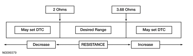
analyzes the deployment loop resistance to determine if a fault exists. The value displayed in the PID is the deployment loop resistance as measured by the
. If the value displayed is lower or higher than the desired range (refer to diagram below), the
can set a DTC. As the deployment loop resistance drifts farther outside the desired range, the chance for a DTC increases. Small variations in resistance can occur due to the effect of road vibrations on terminal fit. Crimps and terminals can be affected by stress and harness movement and can cause an increase in resistance due to wire strain. These variables can result in an intermittent fault. For this reason, the test requires the PID value to be within the desired range before the fault is considered repaired, regardless if the module is reporting an on-demand DTC at time of diagnosis. Following this direction will help make sure that minor changes in resistance do not create a repeat concern. This test uses a process of elimination to diagnose each part of the deployment loop circuit including:
- Wiring
- Connections
- Clockspring
- Driver air bag module
| DTC Description
| Fault Trigger Condition
|
|---|
- B0001:11 — Driver Frontal Stage 1 Deployment Control: Circuit Short to Ground
| When the
senses a short to ground on either driver air bag stage 1 circuit, a fault will be indicated.
|
- B0001:12 — Driver Frontal Stage 1 Deployment Control: Circuit Short to Battery
| When the
senses a short to voltage on either driver air bag stage 1 circuit, a fault will be indicated.
|
- B0001:13 — Driver Frontal Stage 1 Deployment Control: Circuit Open
| When the
measures greater than the desired resistance range between driver air bag stage 1 circuits, a fault will be indicated.
|
- B0001:1A — Driver Frontal Stage 1 Deployment Control: Circuit Resistance Below Threshold
| When the
measures less than the desired resistance range between driver air bag stage 1 circuits, a fault will be indicated.
|
This pinpoint test is intended to diagnose the following:
- Wiring, terminals or connectors
- Clockspring
- Driver air bag module
PINPOINT TEST B: DTCs B0001:11, B0001:12, B0001:13 AND B0001:1A
WARNING: Never probe the electrical connectors on airbag, Safety Canopy or side air curtain assemblies. Failure to follow this instruction may result in the accidental deployment of these assemblies, which increases the risk of serious personal injury or death.
NOTICE:
Use the correct probe adapter(s) from the Flex Probe Kit when taking measurements. Failure to use the correct probe adapter(s) may damage the connector.
Most faults are due to connector and/or wiring concerns. Carry out a thorough inspection and verification before proceeding with the pinpoint test.
NOTE:
Supplemental Restraint System (SRS) components should only be disconnected or reconnected when instructed to do so within a pinpoint test step. Failure to follow this instruction may result in incorrect diagnosis of the
.
NOTE:
Always make sure the correct
component is being installed. Parts released for other vehicles may not be compatible even if they appear physically similar. Check the part number listed in the Ford Catalog Advantage™ or equivalent to make sure the correct component is being installed. If an incorrect
component is installed, DTCs may set.
NOTE:
The
must be fully operational and free of faults before releasing the vehicle to the customer.
| Test Step
| Result / Action to Take
|
|---|
|
B1 RETRIEVE
DTCs
|
|
- Ignition ON.
- Enter the following diagnostic mode on the scan tool: Self Test —
.
- Was DTC B0001:11, B0001:12, B0001:13 or B0001:1A retrieved on-demand during self-test?
| Yes
This fault cannot be cleared until it is corrected and the DTC is no longer retrieved on-demand during self-test.
For DTC B0001:13 or B0001:1A, GO to
B2
.
For DTC B0001:11, GO to
B11
.
For DTC B0001:12, GO to
B14
.
No
This is an intermittent fault when present as a Continuous Memory Diagnostic Trouble Code (CMDTC) only.
For DTC B0001:13 or B0001:1A, GO to
B19
.
For DTC B0001:11, GO to
B20
.
For DTC B0001:12, GO to
B21
.
|
|
B2 CHECK THE DRIVER FRONTAL STAGE 1 DEPLOYMENT CONTROL RESISTANCE (DEPLOY_00_R) PID
|
|
- Enter the following diagnostic mode on the scan tool: DataLogger —
.
- Monitor and record the resistance value displayed by the DEPLOY_00_R PID.
- Does the recorded PID value read between 2 and 3.68 ohms?
| Yes
GO to
B18
.
No
GO to
B3
.
|
|
B3 CHECK THE DRIVER FRONTAL STAGE 1 DEPLOYMENT CONTROL RESISTANCE (DEPLOY_00_R) PID WHILE CARRYING OUT THE HARNESS TEST
|
|
- Remove the lower steering column shroud to access the clockspring connectors.
- While monitoring the DEPLOY_00_R PID, carry out the harness test of the driver air bag circuits and accessible connectors (including any in-line connectors) by wiggling and flexing the wire harness, connectors, tilting and rotating the steering wheel frequently.
- Does the PID value read between 2 and 3.68 ohms while carrying out the harness test?
| Yes
DEPOWER the
and REPAIR the connector, terminals or wire harness or INSTALL a new clockspring as needed. REFER to
Clockspring
in this section.
Refer to Wiring Diagrams Cell
5
, Connector Repair Procedures for schematic and connector information.
GO to
B23
.
No
For PID value less than 2 ohms, GO to
B4
.
For PID value greater than 3.68 ohms, GO to
B7
.
|
|
B4 CHECK THE DRIVER FRONTAL STAGE 1 DEPLOYMENT CONTROL DTC FOR A FAULT STATUS CHANGE (LOW RESISTANCE INDICATED)
|
|
NOTE:
This pinpoint test step will attempt to change the fault reported by the
by inducing a different fault condition. If the fault reported changes, this indicates the
is functioning correctly and is not the source of the fault.
- Ignition OFF.
- Depower the
. Refer to
Supplemental Restraint System (SRS) Depowering and Repowering
in this section.
- Remove the driver air bag module. Refer to
Driver Airbag
in this section.
- Repower the
.
Do not
prove out the
at this time. Refer to
Supplemental Restraint System (SRS) Depowering and Repowering
in this section.
- Ignition ON.
- Enter the following diagnostic mode on the scan tool: Self Test —
.
- DIAGNOSTIC TIP:
When viewing DTCs with the driver air bag module disconnected, open circuit faults would normally be retrieved on stage 1 and 2.
- Did the on-demand DTC change from B0001:1A to B0001:13?
| Yes
GO to
B16
.
No
GO to
B5
.
|
|
B5 CHECK THE DRIVER FRONTAL STAGE 1 DEPLOYMENT CONTROL DTC FOR A FAULT STATUS CHANGE (LOW RESISTANCE INDICATED) (CLOCKSPRING DISCONNECTED)
|
|
NOTE:
This pinpoint test step will attempt to change the fault reported by the
by inducing a different fault condition. If the fault reported changes, this indicates the
is functioning correctly and is not the source of the fault.
- Ignition OFF.
- Disconnect: Clockspring C2274 .
- Ignition ON.
- Enter the following diagnostic mode on the scan tool: Self Test —
.
- DIAGNOSTIC TIP:
When viewing DTCs with the driver air bag module / clockspring disconnected, open circuit faults would normally be retrieved on stage 1 and 2.
- Did the on-demand DTC change from B0001:1A to B0001:13?
| Yes
GO to
B17
.
No
GO to
B6
.
|
|
B6 CHECK THE
FOR LOW RESISTANCE
|
|
| Yes
REPAIR circuits CR101 (VT/BN) and RR101 (YE/GN).
Refer to Wiring Diagrams Cell
5
, Connector Repair Procedures for schematic and connector information.
GO to
B23
.
No
GO to
B18
.
|
|
B7 CHECK THE DRIVER AIR BAG STAGE 1 CIRCUITS FOR AN OPEN
|
|
- Ignition OFF.
- Depower the
. Refer to
Supplemental Restraint System (SRS) Depowering and Repowering
in this section.
- Remove the driver air bag module. Refer to
Driver Airbag
in this section.
- Disconnect:
C2041A and C2041B .
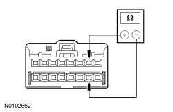
- Measure the resistance between
C2041A, harness side and driver air bag module stage 1 electrical connector, harness side, using the following chart:
| Circuit
| Driver Air Bag Module Stage 1 Electrical Connector
|
|---|
| C2041A-4
| CR101 (VT/BN)
| Driver Air Bag Module Stage 1 electrical connector
| | C2041A-3
| RR101 (YE/GN)
| Driver Air Bag Module Stage 1 electrical connector
|
 - Are the resistances less than 1 ohm?
| Yes
GO to
B9
.
No
GO to
B8
.
|
|
B8 CHECK THE DRIVER AIR BAG STAGE 1 CIRCUITS FOR AN OPEN (CLOCKSPRING DISCONNECTED)
|
|
- Disconnect: Clockspring C2274 .
- Measure the resistance between
C2041A, harness side and clockspring C2274, harness side using the following chart:
| Circuit
| Clockspring
|
|---|
| C2041A-4
| CR101 (VT/BN)
| C2274-1
| | C2041A-3
| RR101 (YE/GN)
| C2274-9
|
 - Are the resistances less than 0.5 ohm?
| Yes
GO to
B17
.
No
REPAIR circuit CR101 (VT/BN) or RR101 (YE/GN).
Refer to Wiring Diagrams Cell
5
, Connector Repair Procedures for schematic and connector information.
GO to
B23
.
|
|
B9 CHECK THE DRIVER FRONTAL STAGE 1 DEPLOYMENT CONTROL DTC FOR A FAULT STATUS CHANGE (OPEN INDICATED)
|
|
NOTE:
This pinpoint test step will attempt to change the fault reported by the
by inducing a different fault condition. If the fault reported changes, this indicates the
is functioning correctly and is not the source of the fault.
- Connect:
C2041A and C2041B .
- Connect a fused jumper wire between driver air bag module stage 1 electrical connector pins 1 and 2, harness side.
- Repower the
.
Do not
prove out the
at this time. Refer to
Supplemental Restraint System (SRS) Depowering and Repowering
in this section.
- Ignition ON.
- Enter the following diagnostic mode on the scan tool: Self Test —
.
- DIAGNOSTIC TIP:
When viewing DTCs with the driver air bag stage 1 circuits shorted together, a low resistance fault would normally be retrieved on stage 1. Stage 2 will show an open circuit fault due to the driver air bag being disconnected.
- Was DTC B0001:1A retrieved on-demand during self-test?
| Yes
GO to
B16
.
No
GO to
B10
.
|
|
B10 CHECK THE DRIVER AIR BAG STAGE 1 CIRCUITS FOR AN OPEN (CLOCKSPRING DISCONNECTED)
|
|
- Ignition OFF.
- Depower the
. Refer to
Supplemental Restraint System (SRS) Depowering and Repowering
in this section.
- Disconnect: Clockspring C2274 .
- Connect a fused jumper wire between clockspring electrical connector C2274 pins 1 and 9, harness side.
- Repower the
.
Do not
prove out the
at this time. Refer to
Supplemental Restraint System (SRS) Depowering and Repowering
in this section.
- Ignition ON.
- Enter the following diagnostic mode on the scan tool: Self Test —
.
- DIAGNOSTIC TIP:
When viewing DTCs with the clockspring stage 1 circuits shorted together, a low resistance fault would normally be retrieved on stage 1. Stage 2 will show an open circuit fault due to the driver air bag being disconnected.
- Was DTC B0001:1A retrieved on-demand during self-test?
| Yes
GO to
B17
.
No
GO to
B18
.
|
|
B11 CHECK THE DRIVER FRONTAL STAGE 1 DEPLOYMENT CONTROL DTC FOR A FAULT STATUS CHANGE (SHORT TO GROUND INDICATED)
|
|
NOTE:
This pinpoint test step will attempt to change the fault reported by the
by inducing a different fault condition. If the fault reported changes, this indicates the
is functioning correctly and is not the source of the fault.
- Ignition OFF.
- Depower the
. Refer to
Supplemental Restraint System (SRS) Depowering and Repowering
in this section.
- Remove the driver air bag module. Refer to
Driver Airbag
in this section.
- Repower the
.
Do not
prove out the
at this time. Refer to
Supplemental Restraint System (SRS) Depowering and Repowering
in this section.
- Ignition ON.
- Enter the following diagnostic mode on the scan tool: Self Test —
.
- DIAGNOSTIC TIP:
When viewing DTCs with the driver air bag module disconnected, open circuit faults would normally be retrieved on stage 1 and 2.
- Did the on-demand DTC change from B0001:11 to B0001:13?
| Yes
GO to
B16
.
No
GO to
B12
.
|
|
B12 CHECK THE DRIVER FRONTAL STAGE 1 DEPLOYMENT CONTROL DTC FOR A FAULT STATUS CHANGE (SHORT TO GROUND INDICATED) (CLOCKSPRING DISCONNECTED)
|
|
NOTE:
This pinpoint test step will attempt to change the fault reported by the
by inducing a different fault condition. If the fault reported changes, this indicates the
is functioning correctly and is not the source of the fault.
- Ignition OFF.
- Disconnect: Clockspring C2274 .
- Ignition ON.
- Enter the following diagnostic mode on the scan tool: Self Test —
.
- DIAGNOSTIC TIP:
When viewing DTCs with the clockspring disconnected, open circuit faults would normally be retrieved on driver air bag stage 1 and 2.
- Did the on-demand DTC change from B0001:11 to B0001:13?
| Yes
GO to
B17
.
No
GO to
B13
.
|
|
B13 CHECK THE DRIVER AIR BAG STAGE 1 CIRCUITS FOR A SHORT TO GROUND
|
|
- Ignition OFF.
- Depower the
. Refer to
Supplemental Restraint System (SRS) Depowering and Repowering
in this section.
- Disconnect:
C2041A and C2041B .
- Measure the resistance between clockspring:
- C2274-1, circuit CR101 (VT/BN), harness side and ground.
- C2274-9, circuit RR101 (YE/GN), harness side and ground.
 - Are the resistances greater than 10,000 ohms?
| Yes
GO to
B18
.
No
Due to the shorting bar feature in the
electrical connector, the fault can exist in either circuit. Do not remove or defeat the shorting bar.
REPAIR circuit CR101 (VT/BN) or RR101 (YE/GN).
Refer to Wiring Diagrams Cell
5
, Connector Repair Procedures for schematic and connector information.
GO to
B23
.
|
|
B14 CHECK THE DRIVER FRONTAL STAGE 1 DEPLOYMENT CONTROL DTC FOR A FAULT STATUS CHANGE (SHORT TO BATTERY INDICATED) (CLOCKSPRING DISCONNECTED)
|
|
NOTE:
This pinpoint test step will attempt to change the fault reported by the
by inducing a different fault condition. If the fault reported changes, this indicates the
is functioning correctly and is not the source of the fault.
- Ignition OFF.
- Depower the
. Refer to
Supplemental Restraint System (SRS) Depowering and Repowering
in this section.
- Remove the driver air bag module. Refer to
Driver Airbag
in this section.
- Disconnect: Clockspring C2274 .
- Repower the
.
Do not
prove out the
at this time. Refer to
Supplemental Restraint System (SRS) Depowering and Repowering
in this section.
- Ignition ON.
- Enter the following diagnostic mode on the scan tool: Self Test —
.
- DIAGNOSTIC TIP:
When viewing DTCs with the driver air bag module/clockspring disconnected, open circuit faults would normally be retrieved on driver air bag stage 1 and 2.
- Did the on-demand DTC change from B0001:12 to B0001:13?
| Yes
GO to
B17
.
No
GO to
B15
.
|
|
B15 CHECK THE DRIVER AIR BAG STAGE 1 CIRCUITS FOR A SHORT TO VOLTAGE
|
|
| Yes
Due to the shorting bar feature in the
electrical connector, the fault can exist in either circuit. Do not remove or defeat the shorting bar.
REPAIR circuit CR101 (VT/BN) or RR101 (YE/GN).
Refer to Wiring Diagrams Cell
5
, Connector Repair Procedures for schematic and connector information.
GO to
B23
.
No
GO to
B18
.
|
|
B16 CONFIRM THE DRIVER AIR BAG MODULE FAULT
|
|
NOTE:
Make sure all restraint system components and the
electrical connectors are connected before carrying out the self-test. If not, DTCs will be recorded.
- Ignition OFF.
- Depower the
. Refer to
Supplemental Restraint System (SRS) Depowering and Repowering
in this section.
- If installed previously, remove the fused jumper wire from the air bag electrical connector.
- Install the driver air bag module. Refer to
Driver Airbag
in this section.
- Repower the
.
Do not
prove out the
at this time. Refer to
Supplemental Restraint System (SRS) Depowering and Repowering
in this section.
- Ignition ON.
- Enter the following diagnostic mode on the scan tool: Self Test —
.
- Was the original DTC retrieved on-demand during self-test?
| Yes
INSTALL a new driver air bag module. REFER to
Driver Airbag
in this section. GO to
B23
.
No
In the process of diagnosing the fault, the fault condition has become intermittent.
Do not install any new
components at this time.
components should only be installed when directed to do so in the pinpoint test.
For DTC B0001:13 or B0001:1A, GO to
B19
.
For DTC B0001:11, GO to
B20
.
For DTC B0001:12, GO to
B21
.
|
|
B17 CONFIRM THE CLOCKSPRING FAULT
|
|
| Yes
INSTALL a new clockspring. REFER to
Clockspring
in this section. GO to
B23
.
No
In the process of diagnosing the fault, the fault condition has become intermittent.
Do not install any new
components at this time.
components should only be installed when directed to do so in the pinpoint test.
For DTC B0001:13 or B0001:1A, GO to
B19
.
For DTC B0001:11, GO to
B20
.
For DTC B0001:12, GO to
B21
.
|
|
B18 CONFIRM THE
FAULT
|
|
NOTE:
Make sure all restraint system components and the
electrical connectors are connected before carrying out the self-test. If not, DTCs will be recorded.
- Ignition OFF.
- Depower the
. Refer to
Supplemental Restraint System (SRS) Depowering and Repowering
in this section.
- Prior to reconnecting any previously disconnected
component:
- inspect connector(s) (including any in-line connectors) for pushed-out, loose or spread terminals and loose or frayed wire connections at terminals.
- inspect wire harness for any damaged, pinched, cut or pierced wires.
- If installed previously, remove the fused jumper wire from the air bag electrical connector.
- If previously removed, install the driver air bag module. Refer to
Driver Airbag
in this section.
- Connect: Clockspring C2274 (if previously disconnected) .
- Connect:
C2041A and C2041B .
- Repower the
.
Do not
prove out the
at this time. Refer to
Supplemental Restraint System (SRS) Depowering and Repowering
in this section.
- Ignition ON.
- Enter the following diagnostic mode on the scan tool: Self Test —
.
- Was the original DTC retrieved on-demand during self-test?
| Yes
INSTALL a new
. REFER to
Restraints Control Module (RCM)
in this section. GO to
B23
.
No
In the process of diagnosing the fault, the fault condition has become intermittent.
Do not install any new
components at this time.
components should only be installed when directed to do so in the pinpoint test.
For DTC B0001:13 or B0001:1A, GO to
B19
.
For DTC B0001:11, GO to
B20
.
For DTC B0001:12, GO to
B21
.
|
|
B19 CHECK THE DRIVER FRONTAL STAGE 1 DEPLOYMENT CONTROL RESISTANCE (DEPLOY_00_R) PID FOR AN INTERMITTENT LOW RESISTANCE OR OPEN CIRCUIT FAULT
|
|
- Enter the following diagnostic mode on the scan tool: DataLogger —
.
- Attempt to recreate the fault by wiggling connectors (including any in-line connectors) and flexing the wire harness, tilting and rotating the steering wheel frequently.
- Does the PID value read between 2 and 3.68 ohms?
| Yes
The fault is not present and cannot be recreated at this time.
Do not install any new
components at this time.
components should only be installed when directed to do so in the pinpoint test.
GO to
B22
.
No
DEPOWER the
and REPAIR as necessary.
Refer to Wiring Diagrams Cell
5
, Connector Repair Procedures for schematic and connector information.
GO to
B23
.
|
|
B20 CHECK THE DRIVER FRONTAL STAGE 1 DEPLOYMENT CONTROL FOR AN INTERMITTENT SHORT TO GROUND FAULT
|
|
- Ignition ON.
- Attempt to recreate the fault by wiggling connectors (including any in-line connectors) and flexing the wire harness, tilting and rotating the steering wheel frequently.
- Enter the following diagnostic mode on the scan tool: Self Test —
.
- Was DTC B0001:11 retrieved on-demand during self-test?
| Yes
DEPOWER the
and REPAIR as necessary.
Refer to Wiring Diagrams Cell
5
, Connector Repair Procedures for schematic and connector information.
GO to
B23
.
No
The fault is not present and cannot be recreated at this time.
Do not install any new
components at this time.
components should only be installed when directed to do so in the pinpoint test.
GO to
B22
.
|
|
B21 CHECK THE DRIVER FRONTAL STAGE 1 DEPLOYMENT CONTROL FOR AN INTERMITTENT SHORT TO BATTERY FAULT
|
|
| Yes
DEPOWER the
and REPAIR as necessary.
Refer to Wiring Diagrams Cell
5
, Connector Repair Procedures for schematic and connector information.
GO to
B23
.
No
The fault is not present and cannot be recreated at this time.
Do not install any new
components at this time.
components should only be installed when directed to do so in the pinpoint test.
GO to
B22
.
|
|
B22 CHECK THE HARNESS AND CONNECTORS
|
|
- Ignition OFF.
- Depower the
. Refer to
Supplemental Restraint System (SRS) Depowering and Repowering
in this section.
- Remove the driver air bag module:
- inspect connector(s) (including any in-line connectors) for corrosion, loose or spread terminals and loose or frayed wire connections at terminals.
- inspect wire harness for any damage, pinched, cut or pierced wires.
- Inspect
C2041A and C2041B
lever/lock for correct operation. Refer to
Restraints Control Module (RCM)
in this section.
- Were any concerns found?
| Yes
REPAIR as necessary.
Refer to Wiring Diagrams Cell
5
, Connector Repair Procedures for schematic and connector information.
GO to
B23
.
No
The fault is not present and cannot be recreated at this time.
Do not install any new
components at this time.
components should only be installed when directed to do so in the pinpoint test.
GO to
B23
.
|
|
B23 CHECK FOR ADDITIONAL
DTCs
|
|
- Ignition OFF.
- WARNING: Turn the ignition OFF and wait one minute to deplete the backup power supply. Failure to follow this instruction may result in serious personal injury or death in the event of an accidental deployment.
- Reconnect all
components (if previously disconnected).
- If previously directed to depower the
, repower the
.
Do not
prove out the
at this time. Refer to
Supplemental Restraint System (SRS) Depowering and Repowering
in this section.
- Ignition ON.
- Enter the following diagnostic mode on the scan tool: Self Test — Restraints .
- NOTE:
When selecting Restraints from the Self Test menu, DTCs will be retrieved from the
and
.
- Are any
and/or
DTCs retrieved on-demand during self-test?
| Yes
Do not clear any DTCs until all DTCs have been resolved. GO to the DTC Charts in this section for pinpoint test direction.
No
CLEAR all
and
. PROVE OUT the
. The repair is complete. RETURN the vehicle to the customer.
|
Pinpoint Test C: DTCs B0002:11, B0002:12, B0002:13 and B0002:1A
Refer to Wiring Diagrams Cell
46
, Supplemental Restraint System for schematic and connector information.
Normal Operation
The Restraints Control Module (RCM) continuously monitors the driver air bag module stage 2 and circuits for the following faults:
- Resistance out of range
- Unexpected voltage
- Short to ground
- Faulted driver air bag module
If a fault is detected, the
will store DTC B0002:11, B0002:12, B0002:13 or B0002:1A in memory and send a message to the Instrument Panel Cluster (IPC) to illuminate the air bag warning indicator.
The
analyzes the deployment loop resistance to determine if a fault exists. The value displayed in the PID is the deployment loop resistance as measured by the
. If the value displayed is lower or higher than the desired range (refer to diagram below), the
can set a DTC. As the deployment loop resistance drifts farther outside the desired range, the chance for a DTC increases. Small variations in resistance can occur due to the effect of road vibrations on terminal fit. Crimps and terminals can be affected by stress and harness movement and can cause an increase in resistance due to wire strain. These variables can result in an intermittent fault. For this reason, the test requires the PID value to be within the desired range before the fault is considered repaired, regardless if the module is reporting an on-demand DTC at time of diagnosis. Following this direction will help make sure that minor changes in resistance do not create a repeat concern. This test uses a process of elimination to diagnose each part of the deployment loop circuit including:
- Wiring
- Connections
- Clockspring
- Driver air bag module
| DTC Description
| Fault Trigger Condition
|
|---|
- B0002:11 — Driver Frontal Stage 2 Deployment Control: Circuit Short to Ground
| When the
senses a short to ground on either driver air bag stage 2 circuit, a fault will be indicated.
|
- B0002:12 — Driver Frontal Stage 2 Deployment Control: Circuit Short to Battery
| When the
senses a short to voltage on either driver air bag stage 2 circuit, a fault will be indicated.
|
- B0002:13 — Driver Frontal Stage 2 Deployment Control: Circuit Open
| When the
measures greater than the desired resistance range between driver air bag stage 2 circuits, a fault will be indicated.
|
- B0002:1A — Driver Frontal Stage 2 Deployment Control: Circuit Resistance Below Threshold
| When the
measures less than the desired resistance range between driver air bag stage 2 circuits, a fault will be indicated.
|
This pinpoint test is intended to diagnose the following:
- Wiring, terminals or connectors
- Clockspring
- Driver air bag module
PINPOINT TEST C: DTCs B0002:11, B0002:12, B0002:13 AND B0002:1A
WARNING: Never probe the electrical connectors on airbag, Safety Canopy or side air curtain assemblies. Failure to follow this instruction may result in the accidental deployment of these assemblies, which increases the risk of serious personal injury or death.
NOTICE:
Use the correct probe adapter(s) from the Flex Probe Kit when taking measurements. Failure to use the correct probe adapter(s) may damage the connector.
Most faults are due to connector and/or wiring concerns. Carry out a thorough inspection and verification before proceeding with the pinpoint test.
NOTE:
Supplemental Restraint System (SRS) components should only be disconnected or reconnected when instructed to do so within a pinpoint test step. Failure to follow this instruction may result in incorrect diagnosis of the
.
NOTE:
Always make sure the correct
component is being installed. Parts released for other vehicles may not be compatible even if they appear physically similar. Check the part number listed in the Ford Catalog Advantage™ or equivalent to make sure the correct component is being installed. If an incorrect
component is installed, DTCs may set.
NOTE:
The
must be fully operational and free of faults before releasing the vehicle to the customer.
| Test Step
| Result / Action to Take
|
|---|
|
C1 RETRIEVE
DTCs
|
|
- Ignition ON.
- Enter the following diagnostic mode on the scan tool: Self Test —
.
- Was DTC B0002:11, B0002:12, B0002:13 or B0002:1A retrieved on-demand during self-test?
| Yes
This fault cannot be cleared until it is corrected and the DTC is no longer retrieved on-demand during self-test.
For DTC B0002:13 or B0002:1A, GO to
C2
.
For DTC B0002:11, GO to
C11
.
For DTC B0002:12, GO to
C14
.
No
This is an intermittent fault when present as a Continuous Memory Diagnostic Trouble Code (CMDTC) only.
For DTC B0002:13 or B0002:1A, GO to
C19
.
For DTC B0002:11, GO to
C20
.
For DTC B0002:12, GO to
C21
.
|
|
C2 CHECK THE DRIVER FRONTAL STAGE 2 DEPLOYMENT CONTROL RESISTANCE (DEPLOY_01_R) PID
|
|
- Enter the following diagnostic mode on the scan tool: DataLogger —
.
- Monitor and record the resistance value displayed by the DEPLOY_01_R PID.
- Does the recorded PID value read between 2 and 3.68 ohms?
| Yes
GO to
C18
.
No
GO to
C3
.
|
|
C3 CHECK THE DRIVER FRONTAL STAGE 2 DEPLOYMENT CONTROL RESISTANCE (DEPLOY_01_R) PID WHILE CARRYING OUT THE HARNESS TEST
|
|
- Remove the lower steering column shroud to access the clockspring connector.
- While monitoring the DEPLOY_01_R PID, carry out the harness test of the driver air bag circuits and accessible connectors (including any in-line connectors), by wiggling and flexing the wire harness, connectors, tilting and rotating the steering wheel frequently.
- Does the PID value read between 2 and 3.68 ohms while carrying out the harness test?
| Yes
DEPOWER the
and REPAIR the connector, terminals or wire harness or INSTALL a new clockspring as needed. REFER to
Clockspring
in this section.
Refer to Wiring Diagrams Cell
5
, Connector Repair Procedures for schematic and connector information.
GO to
C23
.
No
For PID value less than 2 ohms, GO to
C4
.
For PID value greater than 3.68 ohms, GO to
C7
.
|
|
C4 CHECK THE DRIVER FRONTAL STAGE 2 DEPLOYMENT CONTROL DTC FOR A FAULT STATUS CHANGE (LOW RESISTANCE INDICATED)
|
|
NOTE:
This pinpoint test step will attempt to change the fault reported by the
by inducing a different fault condition. If the fault reported changes, this indicates the
is functioning correctly and is not the source of the fault.
- Ignition OFF.
- Depower the
. Refer to
Supplemental Restraint System (SRS) Depowering and Repowering
in this section.
- Remove the driver air bag module. Refer to
Driver Airbag
in this section.
- Repower the
.
Do not
prove out the
at this time. Refer to
Supplemental Restraint System (SRS) Depowering and Repowering
in this section.
- Ignition ON.
- Enter the following diagnostic mode on the scan tool: Self Test —
.
- DIAGNOSTIC TIP:
When viewing DTCs with the driver air bag module disconnected, open circuit faults would normally be retrieved on stage 1 and 2.
- Did the on-demand DTC change from B0002:1A to B0002:13?
| Yes
GO to
C16
.
No
GO to
C5
.
|
|
C5 CHECK THE DRIVER FRONTAL STAGE 2 DEPLOYMENT CONTROL DTC FOR A FAULT STATUS CHANGE (LOW RESISTANCE INDICATED) (CLOCKSPRING DISCONNECTED)
|
|
NOTE:
This pinpoint test step will attempt to change the fault reported by the
by inducing a different fault condition. If the fault reported changes, this indicates the
is functioning correctly and is not the source of the fault.
- Ignition OFF.
- Disconnect: Clockspring C2274 .
- Ignition ON.
- Enter the following diagnostic mode on the scan tool: Self Test —
.
- DIAGNOSTIC TIP:
When viewing DTCs with the driver air bag module/clockspring disconnected, open circuit faults would normally be retrieved on stage 1 and 2.
- Did the on-demand DTC change from B0002:1A to B0002:13?
| Yes
GO to
C17
.
No
GO to
C6
.
|
|
C6 CHECK FOR A SHORT BETWEEN DRIVER AIR BAG STAGE 2 CIRCUITS
|
|
- Ignition OFF.
- Depower the
. Refer to
Supplemental Restraint System (SRS) Depowering and Repowering
in this section.
- Disconnect:
C2041A and C2041B .
- Measure the resistance between C2274-2, circuit CR102 (BU), harness side and C2274-10, circuit RR102 (WH), harness side.
 - Is the resistance greater than 10,000 ohms?
| Yes
GO to
C18
.
No
REPAIR circuits CR102 (BU) and RR102 (WH).
Refer to Wiring Diagrams Cell
5
, Connector Repair Procedures for schematic and connector information.
GO to
C23
.
|
|
C7 CHECK THE DRIVER AIR BAG STAGE 2 CIRCUITS FOR AN OPEN
|
|
- Ignition OFF.
- Depower the
. Refer to
Supplemental Restraint System (SRS) Depowering and Repowering
in this section.
- Remove the driver air bag module. Refer to
Driver Airbag
in this section.
- Disconnect:
C2041A and C2041B .
- Measure the resistance between
C2041A, harness side and driver air bag module stage 2 electrical connector, harness side using the following chart:
| Circuit
| Driver Air Bag Module Electrical Connector
|
|---|
| C2041A-7
| CR102 (BU)
| Driver Air Bag Module Stage 2 electrical connector
| | C2041A-8
| RR102 (WH)
| Driver Air Bag Module Stage 2 electrical connector
|
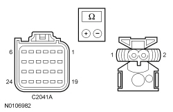 - Are the resistances less than 1 ohm?
| Yes
GO to
C9
.
No
GO to
C8
.
|
|
C8 CHECK THE DRIVER AIR BAG STAGE 2 CIRCUITS FOR AN OPEN (CLOCKSPRING DISCONNECTED)
|
|
- Disconnect: Clockspring C2274 .
- Measure the resistance between
C2041A, harness side and clockspring C2274, harness side using the following chart:
| Circuit
| Clockspring
|
|---|
| C2041A-7
| CR102 (BU)
| C2274-2
| | C2041A-8
| RR102 (WH)
| C2274-10
|
- Are the resistances less than 0.5 ohm?
| Yes
GO to
C17
.
No
REPAIR circuit CR102 (BU) or RR102 (WH).
Refer to Wiring Diagrams Cell
5
, Connector Repair Procedures for schematic and connector information.
GO to
C23
.
|
|
C9 CHECK THE DRIVER FRONTAL STAGE 2 DEPLOYMENT CONTROL DTC FOR A FAULT STATUS CHANGE (OPEN INDICATED)
|
|
NOTE:
This pinpoint test step will attempt to change the fault reported by the
by inducing a different fault condition. If the fault reported changes, this indicates the
is functioning correctly and is not the source of the fault.
- Connect:
C2041A and C2041B .
- Connect a fused jumper wire between driver air bag module stage 2 electrical connector pins 1 and 2, harness side.
- Repower the
.
Do not
prove out the
at this time. Refer to
Supplemental Restraint System (SRS) Depowering and Repowering
in this section.
- Ignition ON.
- Enter the following diagnostic mode on the scan tool: Self Test —
.
- DIAGNOSTIC TIP:
When viewing DTCs with driver air bag module stage 2 circuits shorted together, a low resistance fault would normally be retrieved on stage 2. Stage 1 will show an open circuit fault due to the driver air bag being disconnected.
- Was DTC B0002:1A retrieved on-demand during self-test?
| Yes
GO to
C16
.
No
GO to
C10
.
|
|
C10 CHECK THE DRIVER AIR BAG STAGE 2 CIRCUITS FOR AN OPEN (CLOCKSPRING DISCONNECTED)
|
|
- Ignition OFF.
- Depower the
. Refer to
Supplemental Restraint System (SRS) Depowering and Repowering
in this section.
- Disconnect: Clockspring C2274 .
- Connect a fused jumper wire between clockspring electrical connector C2274 pins 2 and 10, harness side.
- Repower the
.
Do not
prove out the
at this time. Refer to
Supplemental Restraint System (SRS) Depowering and Repowering
in this section.
- Ignition ON.
- Enter the following diagnostic mode on the scan tool: Self Test —
.
- DIAGNOSTIC TIP:
When viewing DTCs with the clockspring stage 2 circuits shorted together, a low resistance fault would normally be retrieved on stage 2. Stage 1 will show an open circuit fault due to the driver air bag being disconnected.
- Was DTC B0002:1A retrieved on-demand during self-test?
| Yes
GO to
C17
.
No
GO to
C18
.
|
|
C11 CHECK THE DRIVER FRONTAL STAGE 2 DEPLOYMENT CONTROL DTC FOR A FAULT STATUS CHANGE (SHORT TO GROUND INDICATED)
|
|
NOTE:
This pinpoint test step will attempt to change the fault reported by the
by inducing a different fault condition. If the fault reported changes, this indicates the
is functioning correctly and is not the source of the fault.
- Ignition OFF.
- Depower the
. Refer to
Supplemental Restraint System (SRS) Depowering and Repowering
in this section.
- Remove the driver air bag module. Refer to
Driver Airbag
in this section.
- Repower the
.
Do not
prove out the
at this time. Refer to
Supplemental Restraint System (SRS) Depowering and Repowering
in this section.
- Ignition ON.
- Enter the following diagnostic mode on the scan tool: Self Test —
.
- DIAGNOSTIC TIP:
When viewing DTCs with the driver air bag module disconnected, open circuit faults would normally be retrieved on stage 1 and 2.
- Did the on-demand DTC change from B0002:11 to B0002:13?
| Yes
GO to
C16
.
No
GO to
C12
.
|
|
C12 CHECK DRIVER FRONTAL STAGE 2 DEPLOYMENT CONTROL DTC FOR A FAULT STATUS CHANGE (SHORT TO GROUND INDICATED) (CLOCKSPRING DISCONNECTED)
|
|
NOTE:
This pinpoint test step will attempt to change the fault reported by the
by inducing a different fault condition. If the fault reported changes, this indicates the
is functioning correctly and is not the source of the fault.
- Ignition OFF.
- Disconnect: Clockspring C2274 .
- Ignition ON.
- Enter the following diagnostic mode on the scan tool: Self Test —
.
- DIAGNOSTIC TIP:
When viewing DTCs with the driver air bag module/clockspring disconnected, open circuit faults would normally be retrieved on stage 1 and 2.
- Did the on-demand DTC change from B0002:11 to B0002:13?
| Yes
GO to
C17
.
No
GO to
C13
.
|
|
C13 CHECK THE DRIVER AIR BAG STAGE 2 CIRCUITS FOR A SHORT TO GROUND
|
|
- Ignition OFF.
- Depower the
. Refer to
Supplemental Restraint System (SRS) Depowering and Repowering
in this section.
- Disconnect:
C2041A and C2041B .
- Measure the resistance between clockspring:
- C2274-2, circuit CR102 (BU), harness side and ground.
- C2274-10, circuit RR102 (WH), harness side and ground.
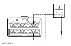 - Are the resistances greater than 10,000 ohms?
| Yes
GO to
C18
.
No
REPAIR circuit CR102 (BU) or RR102 (WH).
Refer to Wiring Diagrams Cell
5
, Connector Repair Procedures for schematic and connector information.
GO to
C23
.
|
|
C14 CHECK THE DRIVER FRONTAL STAGE 2 DEPLOYMENT CONTROL DTC FOR A FAULT STATUS CHANGE (SHORT TO BATTERY INDICATED) (CLOCKSPRING DISCONNECTED)
|
|
NOTE:
This pinpoint test step will attempt to change the fault reported by the
by inducing a different fault condition. If the fault reported changes, this indicates the
is functioning correctly and is not the source of the fault.
- Ignition OFF.
- Depower the
. Refer to
Supplemental Restraint System (SRS) Depowering and Repowering
in this section.
- Remove the driver air bag module. Refer to
Driver Airbag
in this section.
- Disconnect: Clockspring C2274 .
- Repower the
.
Do not
prove out the
at this time. Refer to
Supplemental Restraint System (SRS) Depowering and Repowering
in this section.
- Ignition ON.
- Enter the following diagnostic mode on the scan tool: Self Test —
.
- DIAGNOSTIC TIP:
When viewing DTCs with the driver air bag module/clockspring disconnected, open circuit faults would normally be retrieved on stage 1 and 2.
- Did the on-demand DTC change from B0002:12 to B0002:13?
| Yes
GO to
C17
.
No
GO to
C15
.
|
|
C15 CHECK THE DRIVER AIR BAG STAGE 2 CIRCUITS FOR A SHORT TO VOLTAGE
|
|
| Yes
REPAIR circuit CR102 (BU) or RR102 (WH).
Refer to Wiring Diagrams Cell
5
, Connector Repair Procedures for schematic and connector information.
GO to
C23
.
No
GO to
C18
.
|
|
C16 CONFIRM THE DRIVER AIR BAG MODULE FAULT
|
|
NOTE:
Make sure all restraint system components and the
electrical connectors are connected before carrying out the self-test. If not, DTCs will be recorded.
- Ignition OFF.
- Depower the
. Refer to
Supplemental Restraint System (SRS) Depowering and Repowering
in this section.
- If installed previously, remove the fused jumper wire from the driver air bag electrical connector.
- Install the driver air bag module. Refer to
Driver Airbag
in this section.
- Repower the
.
Do not
prove out the
at this time. Refer to
Supplemental Restraint System (SRS) Depowering and Repowering
in this section.
- Ignition ON.
- Enter the following diagnostic mode on the scan tool: Self Test —
.
- Was the original DTC retrieved on-demand during self-test?
| Yes
INSTALL a new driver air bag module. REFER to
Driver Airbag
in this section. GO to
C23
.
No
In the process of diagnosing the fault, the fault condition has become intermittent.
Do not install any new
components at this time.
components should only be installed when directed to do so in the pinpoint test.
For DTC B0002:13 or B0002:1A, GO to
C19
.
For DTC B0002:11, GO to
C20
.
For DTC B0002:12, GO to
C21
.
|
|
C17 CONFIRM THE CLOCKSPRING FAULT
|
|
NOTE:
Make sure all restraint system components and the
electrical connectors are connected before carrying out the self-test. If not, DTCs will be recorded.
- Ignition OFF.
- Depower the
. Refer to
Supplemental Restraint System (SRS) Depowering and Repowering
in this section.
- Connect: Clockspring C2274 .
- If installed previously, remove the fused jumper wire from the air bag electrical connector.
- Install the driver air bag module. Refer to
Driver Airbag
in this section.
- Repower the
.
Do not
prove out the
at this time. Refer to
Supplemental Restraint System (SRS) Depowering and Repowering
in this section.
- Ignition ON.
- Enter the following diagnostic mode on the scan tool: Self Test —
.
- Was the original DTC retrieved on-demand during self-test?
| Yes
INSTALL a new clockspring. REFER to
Clockspring
in this section. GO to
C23
.
No
In the process of diagnosing the fault, the fault condition has become intermittent.
Do not install any new
components at this time.
components should only be installed when directed to do so in the pinpoint test.
For DTC B0002:13 or B0002:1A, GO to
C19
.
For DTC B0002:11, GO to
C20
.
For DTC B0002:12, GO to
C21
.
|
|
C18 CONFIRM THE
FAULT
|
|
NOTE:
Make sure all restraint system components and the
electrical connectors are connected before carrying out the self-test. If not, DTCs will be recorded.
- Ignition OFF.
- Depower the
. Refer to
Supplemental Restraint System (SRS) Depowering and Repowering
in this section.
- Prior to reconnecting any previously disconnected
component:
- inspect connector(s) (including any in-line connectors) for pushed-out, loose or spread terminals and loose or frayed wire connections at terminals.
- inspect wire harness for any damage, pinched, cut or pierced wires.
- If installed previously, remove the fused jumper wire from the driver air bag electrical connector.
- If previously removed, install the driver air bag module. Refer to
Driver Airbag
in this section.
- Connect: Clockspring C2274 (if previously disconnected) .
- Connect:
C2041A and C2041B .
- Repower the
.
Do not
prove out the
at this time. Refer to
Supplemental Restraint System (SRS) Depowering and Repowering
in this section.
- Ignition ON.
- Enter the following diagnostic mode on the scan tool: Self Test —
.
- Was the original DTC retrieved on-demand during self-test?
| Yes
INSTALL a new
. REFER to
Restraints Control Module (RCM)
in this section. GO to
C23
.
No
In the process of diagnosing the fault, the fault condition has become intermittent.
Do not install any new
components at this time.
components should only be installed when directed to do so in the pinpoint test.
For DTC B0002:13 or B0002:1A, GO to
C19
.
For DTC B0002:11, GO to
C20
.
For DTC B0002:12, GO to
C21
.
|
|
C19 CHECK THE DRIVER FRONTAL STAGE 2 DEPLOYMENT CONTROL RESISTANCE (DEPLOY_01_R) PID FOR AN INTERMITTENT LOW RESISTANCE OR OPEN CIRCUIT FAULT
|
|
- Enter the following diagnostic mode on the scan tool: DataLogger —
.
- Attempt to recreate the fault by wiggling connectors (including any in-line connectors) and flexing the wire harness, tilting and rotating the steering wheel frequently.
- Does the PID value read between 2 and 3.68 ohms?
| Yes
The fault is not present and cannot be recreated at this time.
Do not install any new
components at this time.
components should only be installed when directed to do so in the pinpoint test.
GO to
C22
.
No
DEPOWER the
and REPAIR as necessary.
Refer to Wiring Diagrams Cell
5
, Connector Repair Procedures for schematic and connector information.
GO to
C23
.
|
|
C20 CHECK THE DRIVER FRONTAL STAGE 2 DEPLOYMENT CONTROL FOR AN INTERMITTENT SHORT TO GROUND FAULT
|
|
- Ignition ON.
- Attempt to recreate the fault by wiggling connectors (including any in-line connectors) and flexing the wire harness, tilting and rotating the steering wheel frequently.
- Enter the following diagnostic mode on the scan tool: Self Test —
.
- Was DTC B0002:11 retrieved on-demand during self-test?
| Yes
DEPOWER the
and REPAIR as necessary.
Refer to Wiring Diagrams Cell
5
, Connector Repair Procedures for schematic and connector information.
GO to
C23
.
No
The fault is not present and cannot be recreated at this time.
Do not install any new
components at this time.
components should only be installed when directed to do so in the pinpoint test.
GO to
C22
.
|
|
C21 CHECK THE DRIVER FRONTAL STAGE 2 DEPLOYMENT CONTROL FOR AN INTERMITTENT SHORT TO BATTERY FAULT
|
|
| Yes
DEPOWER the
and REPAIR as necessary.
Refer to Wiring Diagrams Cell
5
, Connector Repair Procedures for schematic and connector information.
GO to
C23
.
No
The fault is not present and cannot be recreated at this time.
Do not install any new
components at this time.
components should only be installed when directed to do so in the pinpoint test.
GO to
C22
.
|
|
C22 CHECK THE HARNESS AND CONNECTORS
|
|
- Ignition OFF.
- Depower the
. Refer to
Supplemental Restraint System (SRS) Depowering and Repowering
in this section.
- Remove the driver air bag module.
- inspect connector(s) (including any in-line connectors) for corrosion, loose or spread terminals and loose or frayed wire connections at terminals.
- inspect wire harness for any damage, pinched, cut or pierced wires.
- Inspect
C2041A and C2041B
lever/lock for correct operation. Refer to
Restraints Control Module (RCM)
in this section.
- Were any concerns found?
| Yes
REPAIR as necessary.
Refer to Wiring Diagrams Cell
5
, Connector Repair Procedures for schematic and connector information.
GO to
C23
.
No
The fault is not present and cannot be recreated at this time.
Do not install any new
components at this time.
components should only be installed when directed to do so in the pinpoint test.
GO to
C23
.
|
|
C23 CHECK FOR ADDITIONAL
DTCs
|
|
- Ignition OFF.
- WARNING: Turn the ignition OFF and wait one minute to deplete the backup power supply. Failure to follow this instruction may result in serious personal injury or death in the event of an accidental deployment.
- Reconnect all
components (if previously disconnected).
- If previously directed to depower the
, repower the
.
Do not
prove out the
at this time. Refer to
Supplemental Restraint System (SRS) Depowering and Repowering
in this section.
- Ignition ON.
- Enter the following diagnostic mode on the scan tool: Self Test — Restraints .
- NOTE:
When selecting Restraints from the Self Test menu, DTCs will be retrieved from the
and
.
- Are any
and/or
DTCs retrieved on-demand during self-test?
| Yes
Do not clear any DTCs until all DTCs have been resolved. GO to the DTC Charts in this section for pinpoint test direction.
No
CLEAR all
and
. PROVE OUT the
. The repair is complete. RETURN the vehicle to the customer.
|
Pinpoint Test D: DTCs B0010:11, B0010:12, B0010:13 and B0010:1A
Refer to Wiring Diagrams Cell
46
, Supplemental Restraint System for schematic and connector information.
Normal Operation
The Restraints Control Module (RCM) continuously monitors the passenger air bag module stage 1 and circuits for the following faults:
- Resistance out of range
- Unexpected voltage
- Short to ground
- Faulted passenger air bag module
If a fault is detected, the
will store DTC B0010:11, B0010:12, B0010:13 or B0010:1A in memory and send a message to the Instrument Panel Cluster (IPC) to illuminate the air bag warning indicator.
The
analyzes the deployment loop resistance to determine if a fault exists. The value displayed in the PID is the deployment loop resistance as measured by the
. If the value displayed is lower or higher than the desired range (refer to diagram below), the
can set a DTC. As the deployment loop resistance drifts farther outside the desired range, the chance for a DTC increases. Small variations in resistance can occur due to the effect of road vibrations on terminal fit. Crimps and terminals can be affected by stress and harness movement and can cause an increase in resistance due to wire strain. These variables can result in an intermittent fault. For this reason, the test requires the PID value to be within the desired range before the fault is considered repaired, regardless if the module is reporting an on-demand DTC at time of diagnosis. Following this direction will help make sure that minor changes in resistance do not create a repeat concern. This test uses a process of elimination to diagnose each part of the deployment loop circuit including:
- Wiring
- Connections
- Passenger air bag module
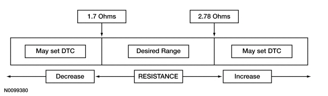
| DTC Description
| Fault Trigger Condition
|
|---|
- B0010:11 — Passenger Frontal Stage 1 Deployment Control: Circuit Short to Ground
| When the
senses a short to ground on either passenger air bag stage 1 circuit, a fault will be indicated.
|
- B0010:12 — Passenger Frontal Stage 1 Deployment Control: Circuit Short to Battery
| When the
senses a short to voltage on either passenger air bag stage 1 circuit, a fault will be indicated.
|
- B0010:13 — Passenger Frontal Stage 1 Deployment Control: Circuit Open
| When the
measures greater than the desired resistance range between passenger air bag stage 1 circuits, a fault will be indicated.
|
- B0010:1A — Passenger Frontal Stage 1 Deployment Control: Circuit Resistance Below Threshold
| When the
measures less than the desired resistance range between passenger air bag stage 1 circuits, a fault will be indicated.
|
This pinpoint test is intended to diagnose the following:
- Wiring, terminals or connectors
- Passenger air bag module
PINPOINT TEST D: DTCs B0010:11, B0010:12, B0010:13 AND B0010:1A
WARNING: Never probe the electrical connectors on airbag, Safety Canopy or side air curtain assemblies. Failure to follow this instruction may result in the accidental deployment of these assemblies, which increases the risk of serious personal injury or death.
NOTICE:
Use the correct probe adapter(s) from the Flex Probe Kit when taking measurements. Failure to use the correct probe adapter(s) may damage the connector.
Most faults are due to connector and/or wiring concerns. Carry out a thorough inspection and verification before proceeding with the pinpoint test.
NOTE:
Supplemental Restraint System (SRS) components should only be disconnected or reconnected when instructed to do so within a pinpoint test step. Failure to follow this instruction may result in incorrect diagnosis of the
.
NOTE:
Always make sure the correct
component is being installed. Parts released for other vehicles may not be compatible even if they appear physically similar. Check the part number listed in the Ford Catalog Advantage™ or equivalent to make sure the correct component is being installed. If an incorrect
component is installed, DTCs may set.
NOTE:
The
must be fully operational and free of faults before releasing the vehicle to the customer.
| Test Step
| Result / Action to Take
|
|---|
|
D1 RETRIEVE
DTCs
|
|
- Ignition ON.
- Enter the following diagnostic mode on the scan tool: Self Test —
.
- Was DTC B0010:11, B0010:12, B0010:13 or B0010:1A retrieved on-demand during self-test?
| Yes
This fault cannot be cleared until it is corrected and the DTC is no longer retrieved on-demand during self-test.
For DTC B0010:13 or B0010:1A, GO to
D2
.
For DTC B0010:11, GO to
D9
.
For DTC B0010:12, GO to
D11
.
No
This is an intermittent fault when present as a Continuous Memory Diagnostic Trouble Code (CMDTC) only.
For DTC B0010:13 or B0010:1A, GO to
D14
.
For DTC B0010:11, GO to
D15
.
For DTC B0010:12, GO to
D16
.
|
|
D2 CHECK THE PASSENGER FRONTAL STAGE 1 DEPLOYMENT CONTROL RESISTANCE (DEPLOY_05_R) PID
|
|
- Enter the following diagnostic mode on the scan tool: DataLogger —
.
- Monitor and record the resistance value displayed by the DEPLOY_05_R PID.
- Does the recorded PID value read between 1.7 and 2.78 ohms?
| Yes
GO to
D13
.
No
GO to
D3
.
|
|
D3 CHECK THE PASSENGER FRONTAL STAGE 1 DEPLOYMENT CONTROL RESISTANCE (DEPLOY_05_R) PID WHILE CARRYING OUT THE HARNESS TEST
|
|
- While monitoring the DEPLOY_05_R PID, carry out the harness test of the passenger air bag module circuits and accessible connectors (including any in-line connectors), by wiggling connectors and flexing the wire harness frequently.
- Does the PID value read between 1.7 and 2.78 ohms while carrying out the harness test?
| Yes
DEPOWER the
and REPAIR the connector, terminals or wire harness as needed.
Refer to Wiring Diagrams Cell
5
, Connector Repair Procedures for schematic and connector information.
GO to
D18
.
No
For PID value less than 1.7 ohms, GO to
D4
.
For PID value greater than 2.78 ohms, GO to
D7
.
|
|
D4 CHECK THE PASSENGER FRONTAL STAGE 1 DEPLOYMENT CONTROL DTC FOR A FAULT STATUS CHANGE (LOW RESISTANCE INDICATED)
|
|
NOTE:
This pinpoint test step will attempt to change the fault reported by the
by inducing a different fault condition. If the fault reported changes, this indicates the
is functioning correctly and is not the source of the fault.
- Ignition OFF.
- Depower the
. Refer to
Supplemental Restraint System (SRS) Depowering and Repowering
in this section.
- Disconnect: Passenger Air Bag Module C256 .
- Repower the
.
Do not
prove out the
at this time. Refer to
Supplemental Restraint System (SRS) Depowering and Repowering
in this section.
- Ignition ON.
- Enter the following diagnostic mode on the scan tool: Self Test —
.
- DIAGNOSTIC TIP:
When viewing DTCs with the passenger air bag module disconnected, open circuit faults would normally be retrieved on passenger air bag stage 1 and 2.
- Did the on-demand DTC change from B0010:1A to B0010:13?
| Yes
GO to
D12
.
No
GO to
D5
.
|
|
D5 CHECK FOR A SHORT BETWEEN PASSENGER AIR BAG STAGE 1 CIRCUITS
|
|
| Yes
GO to
D13
.
No
GO to
D6
.
|
|
D6 CHECK THE
FOR LOW RESISTANCE
|
|
- Disconnect:
C2041A and C2041B .
- Measure the resistance between
C2041A pins 1 and 2, component side.
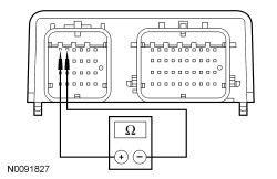 - Is the resistance greater than 10,000 ohms?
| Yes
REPAIR circuits CR103 (GY/BU) and RR103 (VT/GN).
Refer to Wiring Diagrams Cell
5
, Connector Repair Procedures for schematic and connector information.
GO to
D18
.
No
GO to
D13
.
|
|
D7 CHECK THE PASSENGER AIR BAG STAGE 1 CIRCUITS FOR AN OPEN
|
|
- Ignition OFF.
- Depower the
. Refer to
Supplemental Restraint System (SRS) Depowering and Repowering
in this section.
- Disconnect: Passenger Air Bag Module C256 .
- Disconnect:
C2041A and C2041B .
- Measure the resistance between
C2041A, harness side and passenger air bag module C256, harness side using the following chart:
| Circuit
| Passenger Air Bag Module
|
|---|
| C2041A-1
| CR103 (GY/BU)
| C256-3
| | C2041A-2
| RR103 (VT/GN)
| C256-4
|
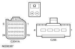 - Are the resistances less than 0.5 ohm?
| Yes
GO to
D8
.
No
REPAIR circuit CR103 (GY/BU) or RR103 (VT/GN).
Refer to Wiring Diagrams Cell
5
, Connector Repair Procedures for schematic and connector information.
GO to
D18
.
|
|
D8 CHECK THE PASSENGER FRONTAL STAGE 1 DEPLOYMENT CONTROL DTC FOR A FAULT STATUS CHANGE (OPEN INDICATED)
|
|
NOTE:
This pinpoint test step will attempt to change the fault reported by the
by inducing a different fault condition. If the fault reported changes, this indicates the
is functioning correctly and is not the source of the fault.
- Connect:
C2041A and C2041B .
- Connect a fused jumper wire between passenger air bag module C256-3, circuit CR103 (GY/BU), harness side and C256-4, circuit RR103 (VT/GN), harness side.
- Repower the
.
Do not
prove out the
at this time. Refer to
Supplemental Restraint System (SRS) Depowering and Repowering
in this section.
- Ignition ON.
- Enter the following diagnostic mode on the scan tool: Self Test —
.
- DIAGNOSTIC TIP:
When viewing DTCs with the passenger air bag module stage 1 circuits shorted together, a low resistance fault would normally be retrieved on stage 1. Stage 2 will show an open circuit fault due to the passenger air bag being disconnected.
- Did the on-demand DTC change from B0010:13 to B0010:1A?
| Yes
GO to
D12
.
No
GO to
D13
.
|
|
D9 CHECK THE PASSENGER FRONTAL STAGE 1 DEPLOYMENT CONTROL DTC FOR A FAULT STATUS CHANGE (SHORT TO GROUND INDICATED)
|
|
NOTE:
This pinpoint test step will attempt to change the fault reported by the
by inducing a different fault condition. If the fault reported changes, this indicates the
is functioning correctly and is not the source of the fault.
- Ignition OFF.
- Depower the
. Refer to
Supplemental Restraint System (SRS) Depowering and Repowering
in this section.
- Disconnect: Passenger Air Bag Module C256 .
- Repower the
.
Do not
prove out the
at this time. Refer to
Supplemental Restraint System (SRS) Depowering and Repowering
in this section.
- Ignition ON.
- Enter the following diagnostic mode on the scan tool: Self Test —
.
- DIAGNOSTIC TIP:
When viewing DTCs with the passenger air bag module disconnected, open circuit faults would normally be retrieved on passenger air bag stage 1 and 2.
- Did the on-demand DTC change from B0010:11 to B0010:13?
| Yes
GO to
D12
.
No
GO to
D10
.
|
|
D10 CHECK THE PASSENGER AIR BAG STAGE 1 CIRCUITS FOR A SHORT TO GROUND
|
|
- Ignition OFF.
- Depower the
. Refer to
Supplemental Restraint System (SRS) Depowering and Repowering
in this section.
- Disconnect:
C2041A and C2041B .
- Measure the resistance between passenger air bag module:
- C256-3, circuit CR103 (GY/BU), harness side and ground.
- C256-4, circuit RR103 (VT/GN), harness side and ground.
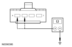 - Are the resistances greater than 10,000 ohms?
| Yes
GO to
D13
.
No
Due to the shorting bar feature in the
electrical connector, the fault can exist in either circuit. Do not remove or defeat the shorting bar.
REPAIR circuit CR103 (GY/BU) or RR103 (VT/GN).
Refer to Wiring Diagrams Cell
5
, Connector Repair Procedures for schematic and connector information.
GO to
D18
.
|
|
D11 CHECK THE PASSENGER AIR BAG STAGE 1 CIRCUITS FOR A SHORT TO VOLTAGE
|
|
| Yes
Due to the shorting bar feature in the
electrical connector, the fault can exist in either circuit. Do not remove or defeat the shorting bar.
REPAIR circuit CR103 (GY/BU) or RR103 (VT/GN).
Refer to Wiring Diagrams Cell
5
, Connector Repair Procedures for schematic and connector information.
GO to
D18
.
No
GO to
D13
.
|
|
D12 CONFIRM THE PASSENGER AIR BAG MODULE FAULT
|
|
NOTE:
Make sure all restraint system components and the
electrical connectors are connected before carrying out the self-test. If not, DTCs will be recorded.
- Ignition OFF.
- Depower the
. Refer to
Supplemental Restraint System (SRS) Depowering and Repowering
in this section.
- If previously installed, remove the fused jumper wire between the passenger air bag module electrical connector.
- Connect: Passenger Air Bag Module C256 (if previously disconnected) .
- Repower the
.
Do not
prove out the
at this time. Refer to
Supplemental Restraint System (SRS) Depowering and Repowering
in this section.
- Enter the following diagnostic mode on the scan tool: Self Test —
.
- Was the original DTC retrieved on-demand during self-test?
| Yes
INSTALL a new passenger air bag module. REFER to
Passenger Airbag
in this section. GO to
D18
.
No
In the process of diagnosing the fault, the fault condition has become intermittent.
Do not install any new
components at this time.
components should only be installed when directed to do so in the pinpoint test.
For DTC B0010:13 or B0010:1A, GO to
D14
.
For DTC B0010:11, GO to
D15
.
For DTC B0010:12, GO to
D16
.
|
|
D13 CONFIRM THE
FAULT
|
|
NOTE:
Make sure all restraint system components and the
electrical connectors are connected before carrying out the self-test. If not, DTCs will be recorded.
- Ignition OFF.
- Depower the
. Refer to
Supplemental Restraint System (SRS) Depowering and Repowering
in this section.
- Prior to reconnecting any previously disconnected
component:
- inspect connector(s) (including any in-line connectors) for pushed out, loose or spread terminals and loose or frayed wire connections at terminals.
- inspect wire harness for any damage, pinched, cut or pierced wires.
- If previously installed, remove the fused jumper wire from the passenger air bag module electrical connector.
- Connect: Passenger Air Bag Module C256 (if previously disconnected) .
- Connect:
C2041A and C2041B .
- Repower the
.
Do not
prove out the
at this time. Refer to
Supplemental Restraint System (SRS) Depowering and Repowering
in this section.
- Ignition ON.
- Enter the following diagnostic mode on the scan tool: Self Test —
.
- Was the original DTC retrieved on-demand during self-test?
| Yes
INSTALL a new
. REFER to
Restraints Control Module (RCM)
in this section. GO to
D18
.
No
In the process of diagnosing the fault, the fault condition has become intermittent.
Do not install any new
components at this time.
components should only be installed when directed to do so in the pinpoint test.
For DTC B0010:13 or B0010:1A, GO to
D14
.
For DTC B0010:11, GO to
D15
.
For DTC B0010:12, GO to
D16
.
|
|
D14 CHECK THE PASSENGER FRONTAL STAGE 1 DEPLOYMENT CONTROL RESISTANCE (DEPLOY_05_R) PID FOR AN INTERMITTENT LOW RESISTANCE OR OPEN CIRCUIT FAULT
|
|
- Enter the following diagnostic mode on the scan tool: DataLogger —
.
- Attempt to recreate the fault by wiggling connectors (including any in-line connectors) and flexing the wire harness frequently.
- Does the PID value read between 1.7 and 2.78 ohms?
| Yes
The fault is not present and cannot be recreated at this time.
Do not install any new
components at this time.
components should only be installed when directed to do so in the pinpoint test.
GO to
D17
.
No
DEPOWER the
and REPAIR as necessary.
Refer to Wiring Diagrams Cell
5
, Connector Repair Procedures for schematic and connector information.
GO to
D18
.
|
|
D15 CHECK THE PASSENGER FRONTAL STAGE 1 DEPLOYMENT CONTROL CIRCUITS FOR AN INTERMITTENT SHORT TO GROUND FAULT
|
|
- Attempt to recreate the fault by wiggling connectors (including any in-line connectors) and flexing the wire harness frequently.
- Enter the following diagnostic mode on the scan tool: Self Test —
.
- Was DTC B0010:11 retrieved on-demand during self-test?
| Yes
DEPOWER the
and REPAIR as necessary.
Refer to Wiring Diagrams Cell
5
, Connector Repair Procedures for schematic and connector information.
GO to
D18
.
No
The fault is not present and cannot be recreated at this time.
Do not install any new
components at this time.
components should only be installed when directed to do so in the pinpoint test.
GO to
D17
.
|
|
D16 CHECK THE PASSENGER FRONTAL STAGE 1 DEPLOYMENT CONTROL CIRCUITS FOR AN INTERMITTENT SHORT TO BATTERY FAULT
|
|
| Yes
DEPOWER the
and REPAIR as necessary.
Refer to Wiring Diagrams Cell
5
, Connector Repair Procedures for schematic and connector information.
GO to
D18
.
No
The fault is not present and cannot be recreated at this time.
Do not install any new
components at this time.
components should only be installed when directed to do so in the pinpoint test.
GO to
D17
.
|
|
D17 CHECK THE HARNESS AND CONNECTORS
|
|
- Ignition OFF.
- Depower the
. Refer to
Supplemental Restraint System (SRS) Depowering and Repowering
in this section.
- Disconnect the passenger air bag module C256 (if not previously disconnected).
- inspect connector(s) (including any in-line connectors) for corrosion, loose or spread terminals and loose or frayed wire connections at terminals.
- inspect wire harness for any damage, pinched, cut or pierced wires.
- Were any concerns found?
| Yes
REPAIR as necessary.
Refer to Wiring Diagrams Cell
5
, Connector Repair Procedures for schematic and connector information.
GO to
D18
.
No
The fault is not present and cannot be recreated at this time.
Do not install any new
components at this time.
components should only be installed when directed to do so in the pinpoint test.
GO to
D18
.
|
|
D18 CHECK FOR ADDITIONAL
DTCs
|
|
- Ignition OFF.
- WARNING: Turn the ignition OFF and wait one minute to deplete the backup power supply. Failure to follow this instruction may result in serious personal injury or death in the event of an accidental deployment.
- Reconnect all
components (if previously disconnected).
- If previously directed to depower the
, repower the
.
Do not
prove out the
at this time. Refer to
Supplemental Restraint System (SRS) Depowering and Repowering
in this section.
- Ignition ON.
- Enter the following diagnostic mode on the scan tool: Self Test — Restraints .
- NOTE:
When selecting Restraints from the Self Test menu, DTCs will be retrieved from the
and Occupant Classification System Module (OCSM).
- Are any
and/or
DTCs retrieved on-demand during self-test?
| Yes
Do not clear any DTCs until all DTCs have been resolved. GO to the DTC Charts in this section for pinpoint test direction.
No
CLEAR all
and
. PROVE OUT the
. The repair is complete. RETURN the vehicle to the customer.
|
Pinpoint Test E: DTCs B0011:11, B0011:12, B0011:13 and B0011:1A
Refer to Wiring Diagrams Cell
46
, Supplemental Restraint System for schematic and connector information.
Normal Operation
The Restraints Control Module (RCM) continuously monitors the passenger air bag module and stage 2 circuits for the following faults:
- Resistance out of range
- Unexpected voltage
- Short to ground
- Faulted passenger air bag module
If a fault is detected, the
will store DTC B0011:11, B0011:12, B0011:13 or B0011:1A in memory and send a message to the Instrument Panel Cluster (IPC) to illuminate the air bag warning indicator.
The
analyzes the deployment loop resistance to determine if a fault exists. The value displayed in the PID is the deployment loop resistance as measured by the
. If the value displayed is lower or higher than the desired range (refer to diagram below), the
can set a DTC. As the deployment loop resistance drifts farther outside the desired range, the chance for a DTC increases. Small variations in resistance can occur due to the effect of road vibrations on terminal fit. Crimps and terminals can be affected by stress and harness movement and can cause an increase in resistance due to wire strain. These variables can result in an intermittent fault. For this reason, the test requires the PID value to be within the desired range before the fault is considered repaired, regardless if the module is reporting an on-demand DTC at time of diagnosis. Following this direction will help make sure that minor changes in resistance do not create a repeat concern. This test uses a process of elimination to diagnose each part of the deployment loop circuit including:
- Wiring
- Connections
- Passenger air bag module
| DTC Description
| Fault Trigger Condition
|
|---|
- B0011:11 — Passenger Frontal Stage 2 Deployment Control: Circuit Short to Ground
| When the
senses a short to ground on either passenger air bag stage 2 circuit, a fault will be indicated.
|
- B0011:12 — Passenger Frontal Stage 2 Deployment Control: Circuit Short to Battery
| When the
senses a short to voltage on either passenger air bag stage 2 circuit, a fault will be indicated.
|
- B0011:13 — Passenger Frontal Stage 2 Deployment Control: Circuit Open
| When the
measures greater than the desired resistance range between passenger air bag stage 2 circuits, a fault will be indicated.
|
- B0011:1A — Passenger Frontal Stage 2 Deployment Control: Circuit Resistance Below Threshold
| When the
measures less than the desired resistance range between passenger air bag stage 2 circuits, a fault will be indicated.
|
This pinpoint test is intended to diagnose the following:
- Wiring, terminals or connectors
- Passenger air bag module
PINPOINT TEST E: DTCs B0011:11, B0011:12, B0011:13 AND B0011:1A
WARNING: Never probe the electrical connectors on airbag, Safety Canopy or side air curtain assemblies. Failure to follow this instruction may result in the accidental deployment of these assemblies, which increases the risk of serious personal injury or death.
NOTICE:
Use the correct probe adapter(s) from the Flex Probe Kit when taking measurements. Failure to use the correct probe adapter(s) may damage the connector.
Most faults are due to connector and/or wiring concerns. Carry out a thorough inspection and verification before proceeding with the pinpoint test.
NOTE:
Supplemental Restraint System (SRS) components should only be disconnected or reconnected when instructed to do so within a pinpoint test step. Failure to follow this instruction may result in incorrect diagnosis of the
.
NOTE:
Always make sure the correct
component is being installed. Parts released for other vehicles may not be compatible even if they appear physically similar. Check the part number listed in the Ford Catalog Advantage™ or equivalent to make sure the correct component is being installed. If an incorrect
component is installed, DTCs may set.
NOTE:
The
must be fully operational and free of faults before releasing the vehicle to the customer.
| Test Step
| Result / Action to Take
|
|---|
|
E1 RETRIEVE
DTCs
|
|
- Ignition ON.
- Enter the following diagnostic mode on the scan tool: Self Test —
.
- Was DTC B0011:11, B0011:12, B0011:13 or B0011:1A retrieved on-demand during self-test?
| Yes
This fault cannot be cleared until it is corrected and the DTC is no longer retrieved on-demand during self-test.
For DTC B0011:13 or B0011:1A, GO to
E2
.
For DTC B0011:11, GO to
E8
.
For DTC B0011:12, GO to
E10
.
No
This is an intermittent fault when present as a Continuous Memory Diagnostic Trouble Code (CMDTC) only.
For DTC B0011:13 or B0011:1A, GO to
E13
.
For DTC B0011:11, GO to
E14
.
For DTC B0011:12, GO to
E15
.
|
|
E2 CHECK THE PASSENGER FRONTAL STAGE 2 DEPLOYMENT CONTROL RESISTANCE (DEPLOY_06_R) PID
|
|
- Enter the following diagnostic mode on the scan tool: DataLogger —
.
- Monitor and record the resistance value displayed by the DEPLOY_06_R PID.
- Does the recorded PID value read between 1.7 and 2.78 ohms?
| Yes
GO to
E12
.
No
GO to
E3
.
|
|
E3 CHECK THE PASSENGER FRONTAL STAGE 2 DEPLOYMENT CONTROL RESISTANCE (DEPLOY_06_R) PID WHILE CARRYING OUT THE HARNESS TEST
|
|
- While monitoring the DEPLOY_06_R PID, carry out the harness test of the passenger air bag module circuits and accessible connectors (including any in-line connectors), by wiggling connectors and flexing the wire harness frequently.
- Does the PID value read between 1.7 and 2.78 ohms while carrying out the harness test?
| Yes
DEPOWER the
and REPAIR the connector, terminals or wire harness as needed.
Refer to Wiring Diagrams Cell
5
, Connector Repair Procedures for schematic and connector information.
GO to
E17
.
No
For PID value less than 1.7 ohms, GO to
E4
.
For PID value greater than 2.78 ohms, GO to
E6
.
|
|
E4 CHECK THE PASSENGER FRONTAL STAGE 2 DEPLOYMENT CONTROL DTC FOR A FAULT STATUS CHANGE (LOW RESISTANCE INDICATED)
|
|
NOTE:
This pinpoint test step will attempt to change the fault reported by the
by inducing a different fault condition. If the fault reported changes, this indicates the
is functioning correctly and is not the source of the fault.
- Ignition OFF.
- Depower the
. Refer to
Supplemental Restraint System (SRS) Depowering and Repowering
in this section.
- Disconnect: Passenger Air Bag Module C256 .
- Repower the
.
Do not
prove out the
at this time. Refer to
Supplemental Restraint System (SRS) Depowering and Repowering
in this section.
- Ignition ON.
- Enter the following diagnostic mode on the scan tool: Self Test —
.
- DIAGNOSTIC TIP:
When viewing DTCs with the passenger air bag module disconnected, open circuit faults would normally be retrieved on passenger air bag stage 1 and 2.
- Did the on-demand DTC change from B0011:1A to B0011:13?
| Yes
GO to
E11
.
No
GO to
E5
.
|
|
E5 CHECK FOR A SHORT BETWEEN PASSENGER AIR BAG STAGE 2 CIRCUITS
|
|
- Ignition OFF.
- Depower the
. Refer to
Supplemental Restraint System (SRS) Depowering and Repowering
in this section.
- Disconnect:
C2041A and C2041B .
- Measure the resistance between C256-1, circuit CR104 (YE/GY), harness side and C256-2, circuit RR104 (WH/BU), harness side.
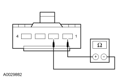 - Is the resistance greater than 10,000 ohms?
| Yes
GO to
E12
.
No
REPAIR circuits CR104 (YE/GY) and RR104 (WH/BU).
Refer to Wiring Diagrams Cell
5
, Connector Repair Procedures for schematic and connector information.
GO to
E17
.
|
|
E6 CHECK THE PASSENGER AIR BAG STAGE 2 CIRCUITS FOR AN OPEN
|
|
- Ignition OFF.
- Depower the
. Refer to
Supplemental Restraint System (SRS) Depowering and Repowering
in this section.
- Disconnect: Passenger Air Bag Module C256 .
- Disconnect:
C2041A and C2041B .
- Measure the resistance between
C2041A, harness side and passenger air bag module C256, harness side using the following chart:
| Circuit
| Passenger Air Bag Module
|
|---|
| C2041A-10
| CR104 (YE/GY)
| C256-1
| | C2041A-9
| RR104 (WH/BU)
| C256-2
|
- Are the resistances less than 0.5 ohm?
| Yes
GO to
E7
.
No
REPAIR circuit CR104 (YE/GY) or RR104 (WH/BU).
Refer to Wiring Diagrams Cell
5
, Connector Repair Procedures for schematic and connector information.
GO to
E17
.
|
|
E7 CHECK THE PASSENGER FRONTAL STAGE 2 DEPLOYMENT CONTROL DTC FOR A FAULT STATUS CHANGE (OPEN INDICATED)
|
|
NOTE:
This pinpoint test step will attempt to change the fault reported by the
by inducing a different fault condition. If the fault reported changes, this indicates the
is functioning correctly and is not the source of the fault.
- Connect:
C2041A and C2041B .
- Connect a fused jumper wire between passenger air bag module C256-1, circuit CR104 (YE/GY), harness side and C256-2, circuit RR104 (WH/BU), harness side.
- Repower the
.
Do not
prove out the
at this time. Refer to
Supplemental Restraint System (SRS) Depowering and Repowering
in this section.
- Ignition ON.
- Enter the following diagnostic mode on the scan tool: Self Test —
.
- DIAGNOSTIC TIP:
When viewing DTCs with the passenger air bag module stage 2 circuits shorted together, a low resistance fault would normally be retrieved on stage 2. Stage 1 will show an open circuit fault due to the passenger air bag module being disconnected.
- Did the on-demand DTC change from B0011:13 to B0011:1A?
| Yes
GO to
E11
.
No
GO to
E12
.
|
|
E8 CHECK THE PASSENGER FRONTAL STAGE 2 DEPLOYMENT CONTROL DTC FOR A FAULT STATUS CHANGE (SHORT TO GROUND INDICATED)
|
|
NOTE:
This pinpoint test step will attempt to change the fault reported by the
by inducing a different fault condition. If the fault reported changes, this indicates the
is functioning correctly and is not the source of the fault.
- Ignition OFF.
- Depower the
. Refer to
Supplemental Restraint System (SRS) Depowering and Repowering
in this section.
- Disconnect: Passenger Air Bag Module C256 .
- Repower the
.
Do not
prove out the
at this time. Refer to
Supplemental Restraint System (SRS) Depowering and Repowering
in this section.
- Ignition ON.
- Enter the following diagnostic mode on the scan tool: Self Test —
.
- DIAGNOSTIC TIP:
When viewing DTCs with the passenger air bag module disconnected, open circuit faults would normally be retrieved on stage 1 and 2.
- Did the on-demand DTC change from B0011:11 to B0011:13?
| Yes
GO to
E11
.
No
GO to
E9
.
|
|
E9 CHECK THE PASSENGER AIR BAG STAGE 2 CIRCUITS FOR A SHORT TO GROUND
|
|
- Ignition OFF.
- Depower the
. Refer to
Supplemental Restraint System (SRS) Depowering and Repowering
in this section.
- Disconnect:
C2041A and C2041B .
- Measure the resistance between passenger air bag module:
- C256-1, circuit CR104 (YE/GY), harness side and ground.
- C256-2, circuit RR104 (WH/BU), harness side and ground.
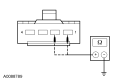 - Are the resistances greater than 10,000 ohms?
| Yes
GO to
E12
.
No
REPAIR circuit CR104 (YE/GY) or RR104 (WH/BU).
Refer to Wiring Diagrams Cell
5
, Connector Repair Procedures for schematic and connector information.
GO to
E17
.
|
|
E10 CHECK THE PASSENGER AIR BAG STAGE 2 CIRCUITS FOR A SHORT TO VOLTAGE
|
|
| Yes
REPAIR circuit CR104 (YE/GY) or RR104 (WH/BU).
Refer to Wiring Diagrams Cell
5
, Connector Repair Procedures for schematic and connector information.
GO to
E17
.
No
GO to
E12
.
|
|
E11 CONFIRM THE PASSENGER AIR BAG MODULE FAULT
|
|
NOTE:
Make sure all restraint system components and the
electrical connectors are connected before carrying out the self-test. If not, DTCs will be recorded.
- Ignition OFF.
- Depower the
. Refer to
Supplemental Restraint System (SRS) Depowering and Repowering
in this section.
- If previously installed, remove the fused jumper wire from the passenger air bag module electrical connector.
- Connect: Passenger Air Bag Module C256 (if previously disconnected) .
- Repower the
.
Do not
prove out the
at this time. Refer to
Supplemental Restraint System (SRS) Depowering and Repowering
in this section.
- Ignition ON.
- Enter the following diagnostic mode on the scan tool: Self Test —
.
- Was the original DTC retrieved on-demand during self-test?
| Yes
INSTALL a new passenger air bag module. REFER to
Passenger Airbag
in this section. GO to
E17
.
No
In the process of diagnosing the fault, the fault condition has become intermittent.
Do not install any new
components at this time.
components should only be installed when directed to do so in the pinpoint test.
For DTC B0011:13 or B0011:1A, GO to
E13
.
For DTC B0011:11, GO to
E14
.
For DTC B0011:12, GO to
E15
.
|
|
E12 CONFIRM THE
FAULT
|
|
NOTE:
Make sure all restraint system components and the
electrical connectors are connected before carrying out the self-test. If not, DTCs will be recorded.
- Ignition OFF.
- Depower the
. Refer to
Supplemental Restraint System (SRS) Depowering and Repowering
in this section.
- Prior to reconnecting any previously disconnected
component:
- inspect connector(s) (including any in-line connectors) for pushed-out, loose or spread terminals and loose or frayed wire connections at terminals.
- inspect wire harness for any damage, pinched, cut or pierced wires.
- If previously installed, remove the fused jumper wire from the passenger air bag module electrical connector.
- Connect: Passenger Air Bag Module C256 (if previously disconnected) .
- Connect:
C2041A and C2041B .
- Repower the
.
Do not
prove out the
at this time. Refer to
Supplemental Restraint System (SRS) Depowering and Repowering
in this section.
- Ignition ON.
- Enter the following diagnostic mode on the scan tool: Self Test —
.
- Was the original DTC retrieved on-demand during self-test?
| Yes
INSTALL a new
. REFER to
Restraints Control Module (RCM)
in this section. GO to
E17
.
No
In the process of diagnosing the fault, the fault condition has become intermittent.
Do not install any new
components at this time.
components should only be installed when directed to do so in the pinpoint test.
For DTC B0011:13 or B0011:1A, GO to
E13
.
For DTC B0011:11, GO to
E14
.
For DTC B0011:12, GO to
E15
.
|
|
E13 CHECK THE PASSENGER FRONTAL STAGE 2 DEPLOYMENT CONTROL RESISTANCE (DEPLOY_06_R) PID FOR AN INTERMITTENT LOW RESISTANCE OR OPEN CIRCUIT FAULT
|
|
- Enter the following diagnostic mode on the scan tool: DataLogger —
.
- Attempt to recreate the fault by wiggling connectors (including any in-line connectors) and flexing the wire harness frequently.
- Does the PID value read between 1.7 and 2.78 ohms?
| Yes
The fault is not present and cannot be recreated at this time.
Do not install any new
components at this time.
components should only be installed when directed to do so in the pinpoint test.
GO to
E16
.
No
DEPOWER the
and REPAIR as necessary.
Refer to Wiring Diagrams Cell
5
, Connector Repair Procedures for schematic and connector information.
GO to
E17
.
|
|
E14 CHECK THE PASSENGER FRONTAL STAGE 2 DEPLOYMENT CONTROL FOR AN INTERMITTENT SHORT TO GROUND FAULT
|
|
- Attempt to recreate the fault by wiggling connectors (including any in-line connectors) and flexing the wire harness frequently.
- Enter the following diagnostic mode on the scan tool: Self Test —
.
- Was DTC B0011:11 retrieved on-demand during self-test?
| Yes
DEPOWER the
and REPAIR as necessary.
Refer to Wiring Diagrams Cell
5
, Connector Repair Procedures for schematic and connector information.
GO to
E17
.
No
The fault is not present and cannot be recreated at this time.
Do not install any new
components at this time.
components should only be installed when directed to do so in the pinpoint test.
GO to
E16
.
|
|
E15 CHECK THE PASSENGER FRONTAL STAGE 2 DEPLOYMENT CONTROL FOR AN INTERMITTENT SHORT TO BATTERY FAULT
|
|
| Yes
DEPOWER the
and REPAIR as necessary.
Refer to Wiring Diagrams Cell
5
, Connector Repair Procedures for schematic and connector information.
GO to
E17
.
No
The fault is not present and cannot be recreated at this time.
Do not install any new
components at this time.
components should only be installed when directed to do so in the pinpoint test.
GO to
E16
.
|
|
E16 CHECK THE HARNESS AND CONNECTORS
|
|
- Ignition OFF.
- Depower the
. Refer to
Supplemental Restraint System (SRS) Depowering and Repowering
in this section.
- Disconnect the passenger air bag module C256.
- inspect connector(s) (including any in-line connectors) for corrosion, loose or spread terminals and loose or frayed wire connections at terminals.
- inspect wire harness for any damage, pinched, cut or pierced wires.
- Were any concerns found?
| Yes
REPAIR as necessary.
Refer to Wiring Diagrams Cell
5
, Connector Repair Procedures for schematic and connector information.
GO to
E17
.
No
The fault is not present and cannot be recreated at this time.
Do not install any new
components at this time.
components should only be installed when directed to do so in the pinpoint test.
GO to
E17
.
|
|
E17 CHECK FOR ADDITIONAL
DTCs
|
|
- Ignition OFF.
- WARNING: Turn the ignition OFF and wait one minute to deplete the backup power supply. Failure to follow this instruction may result in serious personal injury or death in the event of an accidental deployment.
- Reconnect all
components (if previously disconnected).
- If previously directed to depower the
, repower the
.
Do not
prove out the
at this time. Refer to
Supplemental Restraint System (SRS) Depowering and Repowering
in this section.
- Ignition ON.
- Enter the following diagnostic mode on the scan tool: Self Test — Restraints .
- NOTE:
When selecting Restraints from the Self Test menu, DTCs will be retrieved from the
and
.
- Are any
and/or
DTCs retrieved on-demand during self-test?
| Yes
Do not clear any DTCs until all DTCs have been resolved. GO to the DTC Charts in this section for pinpoint test direction.
No
CLEAR all
and
. PROVE OUT the
. The repair is complete. RETURN the vehicle to the customer.
|
Pinpoint Test F: DTCs B0020:11, B0020:12, B0020:13 and B0020:1A
Refer to Wiring Diagrams Cell
46
, Supplemental Restraint System for schematic and connector information.
Normal Operation
The Restraints Control Module (RCM) continuously monitors the driver seat side air bag module and circuits for the following faults:
- Resistance out of range
- Unexpected voltage
- Short to ground
- Faulted driver seat side air bag module
If a fault is detected, the
will store DTC B0020:11, B0020:12, B0020:13 or B0020:1A in memory and send a message to the Instrument Panel Cluster (IPC) to illuminate the air bag warning indicator.
The
analyzes the deployment loop resistance to determine if a fault exists. The value displayed in the PID is the deployment loop resistance as measured by the
. If the value displayed is lower or higher than the desired range (refer to diagram below), the
can set a DTC. As the deployment loop resistance drifts farther outside the desired range, the chance for a DTC increases. Small variations in resistance can occur due to the effect of road vibrations on terminal fit. Crimps and terminals can be affected by stress and harness movement and can cause an increase in resistance due to wire strain. These variables can result in an intermittent fault. For this reason, the test requires the PID value to be within the desired range before the fault is considered repaired, regardless if the module is reporting an on-demand DTC at time of diagnosis. Following this direction will help make sure that minor changes in resistance do not create a repeat concern. This test uses a process of elimination to diagnose each part of the deployment loop circuit including:
- Wiring
- Connections
- Driver seat side air bag module
| DTC Description
| Fault Trigger Condition
|
|---|
- B0020:11 — Left Side Airbag Deployment Control: Circuit Short to Ground
| When the
senses a short to ground on either driver seat side air bag circuit, a fault will be indicated.
|
- B0020:12 — Left Side Airbag Deployment Control: Circuit Short to Battery
| When the
senses a short to voltage on either driver seat side air bag circuit, a fault will be indicated.
|
- B0020:13 — Left Side Airbag Deployment Control: Circuit Open
| When the
measures greater than the desired resistance range between the driver seat side air bag circuits, a fault will be indicated.
|
- B0020:1A — Left Side Airbag Deployment Control: Circuit Resistance Below Threshold
| When the
measures less than the desired resistance range between the driver seat side air bag circuits, a fault will be indicated.
|
This pinpoint test is intended to diagnose the following:
- Wiring, terminals or connectors
- Driver seat side air bag module
PINPOINT TEST F: DTCs B0020:11, B0020:12, B0020:13 AND B0020:1A
WARNING: Never probe the electrical connectors on airbag, Safety Canopy or side air curtain assemblies. Failure to follow this instruction may result in the accidental deployment of these assemblies, which increases the risk of serious personal injury or death.
WARNING: Never disassemble or tamper with seat belt deployable components, including pretensioners, load limiters and inflators. Never back probe deployable device electrical connectors. Tampering or back probing may cause an accidental deployment and result in personal injury or death.
NOTICE:
Use the correct probe adapter(s) from the Flex Probe Kit when taking measurements. Failure to use the correct probe adapter(s) may damage the connector.
Most faults are due to connector and/or wiring concerns. Carry out a thorough inspection and verification before proceeding with the pinpoint test.
NOTE:
Supplemental Restraint System (SRS) components should only be disconnected or reconnected when instructed to do so within a pinpoint test step. Failure to follow this instruction may result in incorrect diagnosis of the
.
NOTE:
Always make sure the correct
component is being installed. Parts released for other vehicles may not be compatible even if they appear physically similar. Check the part number listed in the Ford Catalog Advantage™ or equivalent to make sure the correct component is being installed. If an incorrect
component is installed, DTCs may set.
NOTE:
The
must be fully operational and free of faults before releasing the vehicle to the customer.
| Test Step
| Result / Action to Take
|
|---|
|
F1 RETRIEVE
DTCs
|
|
- Ignition ON.
- Enter the following diagnostic mode on the scan tool: Self Test —
.
- Was DTC B0020:11, B0020:12, B0020:13 or B0020:1A retrieved on-demand during self-test?
| Yes
This fault cannot be cleared until it is corrected and the DTC is no longer retrieved on-demand during self-test.
For DTC B0020:13 or B0020:1A, GO to
F2
.
For DTC B0020:11, GO to
F8
.
For DTC B0020:12, GO to
F10
.
No
This is an intermittent fault when present as a Continuous Memory Diagnostic Trouble Code (CMDTC) only.
For DTC B0020:13 or B0020:1A, GO to
F13
.
For DTC B0020:11, GO to
F14
.
For DTC B0020:12, GO to
F15
.
|
|
F2 CHECK THE LEFT SIDE AIRBAG DEPLOYMENT CONTROL RESISTANCE (DEPLOY_10_R) PID
|
|
- Enter the following diagnostic mode on the scan tool: DataLogger —
.
- Monitor and record the resistance value displayed by the DEPLOY_10_R PID.
- Does the recorded PID value read between 1.7 and 2.78 ohms?
| Yes
GO to
F12
.
No
GO to
F3
.
|
|
F3 CHECK THE LEFT SIDE AIRBAG DEPLOYMENT CONTROL RESISTANCE (DEPLOY_10_R) PID WHILE CARRYING OUT THE HARNESS TEST
|
|
- While monitoring the DEPLOY_10_R PID, carry out the harness test of the driver seat side air bag circuits and accessible connectors (including any in-line connectors) by wiggling connectors and flexing the wire harness frequently.
- Does the PID value read between 1.7 and 2.78 ohms while carrying out the harness test?
| Yes
DEPOWER the
and REPAIR the connector, terminals or wire harness as needed.
Refer to Wiring Diagrams Cell
5
, Connector Repair Procedures for schematic and connector information.
GO to
F17
.
No
For PID value less than 1.7 ohms, GO to
F4
.
For PID value greater than 2.78 ohms, GO to
F6
.
|
|
F4 CHECK THE LEFT SIDE AIRBAG DEPLOYMENT CONTROL DTC FOR A FAULT STATUS CHANGE (LOW RESISTANCE INDICATED)
|
|
NOTE:
This pinpoint test step will attempt to change the fault reported by the
by inducing a different fault condition. If the fault reported changes, this indicates the
is functioning correctly and is not the source of the fault.
- Ignition OFF.
- Depower the
. Refer to
Supplemental Restraint System (SRS) Depowering and Repowering
in this section.
- Disconnect: Driver Seat Side Air Bag Module C367 .
- Repower the
.
Do not
prove out the
at this time. Refer to
Supplemental Restraint System (SRS) Depowering and Repowering
in this section.
- Ignition ON.
- Enter the following diagnostic mode on the scan tool: Self Test —
.
- DIAGNOSTIC TIP:
When viewing DTCs with the driver seat side air bag module disconnected, an open circuit fault would normally be retrieved.
- Did the on-demand DTC change from B0020:1A to B0020:13?
| Yes
GO to
F11
.
No
GO to
F5
.
|
|
F5 CHECK FOR A SHORT BETWEEN DRIVER SEAT SIDE AIR BAG CIRCUITS
|
|
- Ignition OFF.
- Depower the
. Refer to
Supplemental Restraint System (SRS) Depowering and Repowering
in this section.
- Disconnect:
C2041A and C2041B .
- Measure the resistance between driver seat side air bag module C367-1, circuit CR105 (GN/BU), harness side and C367-2, circuit RR105 (GY/YE), harness side.
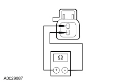 - Is the resistance greater than 10,000 ohms?
| Yes
GO to
F12
.
No
REPAIR circuits CR105 (GN/BU) and RR105 (GY/YE).
Refer to Wiring Diagrams Cell
5
, Connector Repair Procedures for schematic and connector information.
GO to
F17
.
|
|
F6 CHECK THE DRIVER SEAT SIDE AIR BAG CIRCUITS FOR AN OPEN
|
|
- Ignition OFF.
- Depower the
. Refer to
Supplemental Restraint System (SRS) Depowering and Repowering
in this section.
- Disconnect: Driver Seat Side Air Bag Module C367 .
- Disconnect:
C2041A and C2041B .
- Measure the resistance between
C2041B, harness side and driver seat side air bag module C367, harness side using the following chart:
| Circuit
| Driver Seat Side Air Bag Module
|
|---|
| C2041B-2
| CR105 (GN/BU)
| C367-1
| | C2041B-1
| RR105 (GY/YE)
| C367-2
|
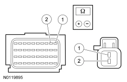 - Are the resistances less than 0.5 ohm?
| Yes
GO to
F7
.
No
REPAIR circuit CR105 (GN/BU) or RR105 (GY/YE).
Refer to Wiring Diagrams Cell
5
, Connector Repair Procedures for schematic and connector information.
GO to
F17
.
|
|
F7 CHECK THE LEFT SIDE AIRBAG DEPLOYMENT CONTROL DTC FOR A FAULT STATUS CHANGE (OPEN INDICATED)
|
|
NOTE:
This pinpoint test step will attempt to change the fault reported by the
by inducing a different fault condition. If the fault reported changes, this indicates the
is functioning correctly and is not the source of the fault.
- Connect:
C2041A and C2041B .
- Connect a fused jumper wire between driver seat side air bag C367-1, circuit CR105 (GN/BU), harness side and C367-2, circuit RR105 (GY/YE), harness side.
- Repower the
.
Do not
prove out the
at this time. Refer to
Supplemental Restraint System (SRS) Depowering and Repowering
in this section.
- Ignition ON.
- Enter the following diagnostic mode on the scan tool: Self Test —
.
- DIAGNOSTIC TIP:
When viewing DTCs with the driver seat side air bag module circuits shorted together, a low resistance fault would normally be retrieved.
- Did the on-demand DTC change from B0020:13 to B0020:1A?
| Yes
GO to
F11
.
No
GO to
F12
.
|
|
F8 CHECK THE LEFT SIDE AIRBAG DEPLOYMENT CONTROL DTC FOR A FAULT STATUS CHANGE (SHORT TO GROUND INDICATED)
|
|
NOTE:
This pinpoint test step will attempt to change the fault reported by the
by inducing a different fault condition. If the fault reported changes, this indicates the
is functioning correctly and is not the source of the fault.
- Ignition OFF.
- Depower the
. Refer to
Supplemental Restraint System (SRS) Depowering and Repowering
in this section.
- Disconnect: Driver Seat Side Air Bag Module C367 .
- Repower the
.
Do not
prove out the
at this time. Refer to
Supplemental Restraint System (SRS) Depowering and Repowering
in this section.
- Ignition ON.
- Enter the following diagnostic mode on the scan tool: Self Test —
.
- DIAGNOSTIC TIP:
When viewing DTCs with the driver seat side air bag module disconnected, an open circuit fault would normally be retrieved.
- Did the on-demand DTC change from B0020:11 to B0020:13?
| Yes
GO to
F11
.
No
GO to
F9
.
|
|
F9 CHECK THE DRIVER SEAT SIDE AIR BAG CIRCUITS FOR A SHORT TO GROUND
|
|
- Ignition OFF.
- Depower the
. Refer to
Supplemental Restraint System (SRS) Depowering and Repowering
in this section.
- Disconnect:
C2041A and C2041B .
- Measure the resistance between driver seat side air bag module:
- C367-1, circuit CR105 (GN/BU), harness side and ground.
- C367-2, circuit RR105 (GY/YE), harness side and ground.
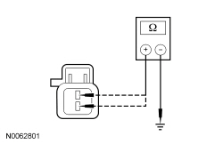 - Are the resistances greater than 10,000 ohms?
| Yes
GO to
F12
.
No
REPAIR circuit CR105 (GN/BU) or RR105 (GY/YE).
Refer to Wiring Diagrams Cell
5
, Connector Repair Procedures for schematic and connector information.
GO to
F17
.
|
|
F10 CHECK THE DRIVER SEAT SIDE AIR BAG CIRCUITS FOR A SHORT TO VOLTAGE
|
|
| Yes
REPAIR circuit CR105 (GN/BU) or RR105 (GY/YE).
Refer to Wiring Diagrams Cell
5
, Connector Repair Procedures for schematic and connector information.
GO to
F17
.
No
GO to
F12
.
|
|
F11 CONFIRM THE DRIVER SEAT SIDE AIR BAG MODULE FAULT
|
|
NOTE:
Make sure all restraint system components and the
electrical connectors are connected before carrying out self-test. If not, DTCs will be recorded.
- Ignition OFF.
- Depower the
. Refer to
Supplemental Restraint System (SRS) Depowering and Repowering
in this section.
- If previously installed, remove the fused jumper wire from the driver seat side air bag C367.
- Connect: Driver Seat Side Air Bag Module C367 .
- Connect:
C2041A and C2041B .
- Repower the
.
Do not
prove out the
at this time. Refer to
Supplemental Restraint System (SRS) Depowering and Repowering
in this section.
- Ignition ON.
- Enter the following diagnostic mode on the scan tool: Self Test —
.
- Was the original DTC retrieved on-demand during self-test?
| Yes
REMOVE and INSPECT the driver seat side air bag module harness for damage. REFER to
Side Airbag
in this section. If a concern is found, REPAIR as necessary.
Refer to Wiring Diagrams Cell
5
, Connector Repair Procedures for schematic and connector information.
If a concern
was not
found, INSTALL a new driver seat side air bag module. REFER to
Side Airbag
in this section. GO to
F17
.
No
In the process of diagnosing the fault, the fault condition has become intermittent.
Do not install any new
components at this time.
components should only be installed when directed to do so in the pinpoint test.
For DTC B0020:13 or B0020:1A, GO to
F13
.
For DTC B0020:11, GO to
F14
.
For DTC B0020:12, GO to
F15
.
|
|
F12 CONFIRM THE
FAULT
|
|
NOTE:
Make sure all restraint system components and the
electrical connectors are connected before carrying out the self-test. If not, DTCs will be recorded.
- Ignition OFF.
- Depower the
. Refer to
Supplemental Restraint System (SRS) Depowering and Repowering
in this section.
- Prior to reconnecting any previously disconnected
component:
- inspect connector(s) (including any in-line connectors) for pushed-out, loose or spread terminals and loose or frayed wire connections at terminals.
- inspect wire harness for any damage, pinched, cut or pierced wires.
- If previously installed, remove the fused jumper wire from the driver seat side air bag C367.
- Connect: Driver Seat Side Air Bag Module C367 .
- Connect:
C2041A and C2041B (if previously disconnected) .
- Repower the
.
Do not
prove out the
at this time. Refer to
Supplemental Restraint System (SRS) Depowering and Repowering
in this section.
- Ignition ON.
- Enter the following diagnostic mode on the scan tool: Self Test —
.
- Was the original DTC retrieved on-demand during self-test?
| Yes
INSTALL a new
. REFER to
Restraints Control Module (RCM)
in this section. GO to
F17
.
No
In the process of diagnosing the fault, the fault condition has become intermittent.
Do not install any new
components at this time.
components should only be installed when directed to do so in the pinpoint test.
For DTC B0020:13 or B0020:1A, GO to
F13
.
For DTC B0020:11, GO to
F14
.
For DTC B0020:12, GO to
F15
.
|
|
F13 CHECK THE LEFT SIDE AIRBAG DEPLOYMENT CONTROL RESISTANCE (DEPLOY_10_R) PID FOR AN INTERMITTENT LOW RESISTANCE OR OPEN CIRCUIT FAULT
|
|
- Enter the following diagnostic mode on the scan tool: DataLogger —
.
- Attempt to recreate the fault by wiggling connectors (including any in-line connectors) and flexing the wire harness frequently.
- Does the PID value read between 1.7 and 2.78 ohms?
| Yes
The fault is not present and cannot be recreated at this time.
Do not install any new
components at this time.
components should only be installed when directed to do so in the pinpoint test.
GO to
F16
.
No
DEPOWER the
and REPAIR as necessary.
Refer to Wiring Diagrams Cell
5
, Connector Repair Procedures for schematic and connector information.
GO to
F17
.
|
|
F14 CHECK THE LEFT SIDE AIRBAG DEPLOYMENT CONTROL FOR AN INTERMITTENT SHORT TO GROUND FAULT
|
|
- Attempt to recreate the fault by wiggling connectors (including any in-line connectors) and flexing the wire harness frequently.
- Enter the following diagnostic mode on the scan tool: Self Test —
.
- Was DTC B0020:11 retrieved on-demand during self-test?
| Yes
DEPOWER the
and REPAIR as necessary.
Refer to Wiring Diagrams Cell
5
, Connector Repair Procedures for schematic and connector information.
GO to
F17
.
No
The fault is not present and cannot be recreated at this time.
Do not install any new
components at this time.
components should only be installed when directed to do so in the pinpoint test.
GO to
F16
.
|
|
F15 CHECK THE LEFT SIDE AIRBAG DEPLOYMENT CONTROL FOR AN INTERMITTENT SHORT TO BATTERY FAULT
|
|
| Yes
DEPOWER the
and REPAIR as necessary.
Refer to Wiring Diagrams Cell
5
, Connector Repair Procedures for schematic and connector information.
GO to
F17
.
No
The fault is not present and cannot be recreated at this time.
Do not install any new
components at this time.
components should only be installed when directed to do so in the pinpoint test.
GO to
F16
.
|
|
F16 CHECK THE HARNESS AND CONNECTORS
|
|
- Ignition OFF.
- Depower the
. Refer to
Supplemental Restraint System (SRS) Depowering and Repowering
in this section.
- Disconnect the driver seat side air bag module C367:
- inspect connector(s) (including any in-line connectors) for corrosion, loose or spread terminals and loose or frayed wire connections at terminals.
- inspect wire harness for any damage, pinched, cut or pierced wires.
- Were any concerns found?
| Yes
REPAIR as necessary.
Refer to Wiring Diagrams Cell
5
, Connector Repair Procedures for schematic and connector information.
GO to
F17
.
No
The fault is not present and cannot be recreated at this time.
Do not install any new
components at this time.
components should only be installed when directed to do so in the pinpoint test.
GO to
F17
.
|
|
F17 CHECK FOR ADDITIONAL
DTCs
|
|
- Ignition OFF.
- WARNING: Turn the ignition OFF and wait one minute to deplete the backup power supply. Failure to follow this instruction may result in serious personal injury or death in the event of an accidental deployment.
- Reconnect all
components (if previously disconnected).
- If previously directed to depower the
, repower the
.
Do not
prove out the
at this time. Refer to
Supplemental Restraint System (SRS) Depowering and Repowering
in this section.
- Ignition ON.
- Enter the following diagnostic mode on the scan tool: Self Test — Restraints .
- NOTE:
When selecting Restraints from the Self Test menu, DTCs will be retrieved from the
and
.
- Are any
and/or
DTCs retrieved on-demand during self-test?
| Yes
Do not clear any DTCs until all DTCs have been resolved. GO to the DTC Charts in this section for pinpoint test direction.
No
CLEAR all
and
. PROVE OUT the
. The repair is complete. RETURN the vehicle to the customer.
|
Pinpoint Test G: DTCs B0028:11, B0028:12, B0028:13 and B0028:1A
Refer to Wiring Diagrams Cell
46
, Supplemental Restraint System for schematic and connector information.
Normal Operation
The Restraints Control Module (RCM) continuously monitors the passenger seat side air module and bag circuits for the following faults:
- Resistance out of range
- Unexpected voltage
- Short to ground
- Faulted passenger seat side air bag module
If a fault is detected, the
will store DTC B0028:11, B0028:12, B0028:13 or B0028:1A in memory and send a message to the Instrument Panel Cluster (IPC) to illuminate the air bag warning indicator.
The
analyzes the deployment loop resistance to determine if a fault exists. The value displayed in the PID is the deployment loop resistance as measured by the
. If the value displayed is lower or higher than the desired range (refer to diagram below), the
can set a DTC. As the deployment loop resistance drifts farther outside the desired range, the chance for a DTC increases. Small variations in resistance can occur due to the effect of road vibrations on terminal fit. Crimps and terminals can be affected by stress and harness movement and can cause an increase in resistance due to wire strain. These variables can result in an intermittent fault. For this reason, the test requires the PID value to be within the desired range before the fault is considered repaired, regardless if the module is reporting an on-demand DTC at time of diagnosis. Following this direction will help make sure that minor changes in resistance do not create a repeat concern. This test uses a process of elimination to diagnose each part of the deployment loop circuit including:
- Wiring
- Connections
- Passenger seat side air bag module
| DTC Description
| Fault Trigger Condition
|
|---|
- B0028:11 — Right Side Airbag Deployment Control: Circuit Short to Ground
| When the
senses a short to ground on either passenger seat side air bag circuit, a fault will be indicated.
|
- B0028:12 — Right Side Airbag Deployment Control: Circuit Short to Battery
| When the
senses a short to voltage on either passenger seat side air bag circuit, a fault will be indicated.
|
- B0028:13 — Right Side Airbag Deployment Control: Circuit Open
| When the
measures greater than the desired resistance range between the passenger seat side air bag circuits, a fault will be indicated.
|
- B0028:1A — Right Side Airbag Deployment Control: Circuit Resistance Below Threshold
| When the
measures less than the desired resistance range between the passenger seat side air bag circuits, a fault will be indicated.
|
This pinpoint test is intended to diagnose the following:
- Wiring, terminals or connectors
- Passenger seat side air bag module
PINPOINT TEST G: DTCs B0028:11, B0028:12, B0028:13 AND B0028:1A
WARNING: Never disassemble or tamper with seat belt deployable components, including pretensioners, load limiters and inflators. Never back probe deployable device electrical connectors. Tampering or back probing may cause an accidental deployment and result in personal injury or death.
WARNING: Never probe the electrical connectors on airbag, Safety Canopy or side air curtain assemblies. Failure to follow this instruction may result in the accidental deployment of these assemblies, which increases the risk of serious personal injury or death.
NOTICE:
Use the correct probe adapter(s) from the Flex Probe Kit when taking measurements. Failure to use the correct probe adapter(s) may damage the connector.
Most faults are due to connector and/or wiring concerns. Carry out a thorough inspection and verification before proceeding with the pinpoint test.
NOTE:
Supplemental Restraint System (SRS) components should only be disconnected or reconnected when instructed to do so within a pinpoint test step. Failure to follow this instruction may result in incorrect diagnosis of the
.
NOTE:
Always make sure the correct
component is being installed. Parts released for other vehicles may not be compatible even if they appear physically similar. Check the part number listed in the Ford Catalog Advantage™ or equivalent to make sure the correct component is being installed. If an incorrect
component is installed, DTCs may set.
NOTE:
The
must be fully operational and free of faults before releasing the vehicle to the customer.
| Test Step
| Result / Action to Take
|
|---|
|
G1 RETRIEVE
DTCs
|
|
- Ignition ON.
- Enter the following diagnostic mode on the scan tool: Self Test —
.
- Was DTC B0028:11, B0028:12, B0028:13 or B0028:1A retrieved on-demand during self-test?
| Yes
This fault cannot be cleared until it is corrected and the DTC is no longer retrieved on-demand during self-test.
For DTC B0028:13 or B0028:1A, GO to
G2
.
For DTC B0028:11, GO to
G8
.
For DTC B0028:12, GO to
G10
.
No
This is an intermittent fault when present as a Continuous Memory Diagnostic Trouble Code (CMDTC) only.
For DTC B0028:13 or B0028:1A, GO to
G13
.
For DTC B0028:11, GO to
G14
.
For DTC B0028:12, GO to
G15
.
|
|
G2 CHECK THE RIGHT SIDE AIRBAG DEPLOYMENT CONTROL RESISTANCE (DEPLOY_13_R) PID
|
|
- Enter the following diagnostic mode on the scan tool: DataLogger —
.
- Monitor and record the resistance value displayed by the DEPLOY_13_R PID.
- Does the recorded PID value read between 1.7 and 2.78 ohms?
| Yes
GO to
G12
.
No
GO to
G3
.
|
|
G3 CHECK THE RIGHT SIDE AIRBAG DEPLOYMENT CONTROL RESISTANCE (DEPLOY_13_R) PID WHILE CARRYING OUT THE HARNESS TEST
|
|
- While monitoring the DEPLOY_13_R PID, carry out the harness test of the passenger side air bag circuits and accessible connectors (including any in-line connectors) by wiggling connectors and flexing the wire harness frequently.
- Does the PID value read between 1.7 and 2.78 ohms while carrying out the harness test?
| Yes
DEPOWER the
and REPAIR the connector, terminals or wire harness as needed.
Refer to Wiring Diagrams Cell
5
, Connector Repair Procedures for schematic and connector information.
GO to
G17
.
No
For PID value less than 1.7 ohms, GO to
G4
.
For PID value greater than 2.78 ohms, GO to
G6
.
|
|
G4 CHECK THE RIGHT SIDE AIRBAG DEPLOYMENT CONTROL DTC FOR A FAULT STATUS CHANGE (LOW RESISTANCE INDICATED)
|
|
NOTE:
This pinpoint test step will attempt to change the fault reported by the
by inducing a different fault condition. If the fault reported changes, this indicates the
is functioning correctly and is not the source of the fault.
- Ignition OFF.
- Depower the
. Refer to
Supplemental Restraint System (SRS) Depowering and Repowering
in this section.
- Disconnect: Passenger Seat Side Air Bag Module C337 .
- Repower the
.
Do not
prove out the
at this time. Refer to
Supplemental Restraint System (SRS) Depowering and Repowering
in this section.
- Ignition ON.
- Enter the following diagnostic mode on the scan tool: Self Test —
.
- DIAGNOSTIC TIP:
When viewing DTCs with the passenger seat side air bag module disconnected, an open circuit fault would normally be retrieved.
- Did the on-demand DTC change from B0028:1A to B0028:13?
| Yes
GO to
G11
.
No
GO to
G5
.
|
|
G5 CHECK FOR A SHORT BETWEEN PASSENGER SEAT SIDE AIR BAG CIRCUITS
|
|
- Ignition OFF.
- Depower the
. Refer to
Supplemental Restraint System (SRS) Depowering and Repowering
in this section.
- Disconnect:
C2041A and C2041B .
- Measure the resistance between passenger seat side air bag C337-1, circuit CR106 (VT/GY), harness side and C337-2, circuit RR106 (YE/OG), harness side.
- Is the resistance greater than 10,000 ohms?
| Yes
GO to
G12
.
No
REPAIR circuits CR106 (VT/GY) and RR106 (YE/OG).
Refer to Wiring Diagrams Cell
5
, Connector Repair Procedures for schematic and connector information.
GO to
G17
.
|
|
G6 CHECK THE PASSENGER SEAT SIDE AIR BAG CIRCUITS FOR AN OPEN
|
|
- Ignition OFF.
- Depower the
. Refer to
Supplemental Restraint System (SRS) Depowering and Repowering
in this section.
- Disconnect: Passenger Seat Side Air Bag Module C337 .
- Disconnect:
C2041A and C2041B .
- Measure the resistance between
C2041B, harness side and passenger seat side air bag module C337, harness side using the following chart:
| Circuit
| Passenger Seat Side Air Bag Module
|
|---|
| C204B-12
| CR106 (VT/GY)
| C337-1
| | C204B-11
| RR106 (YE/OG)
| C337-2
|
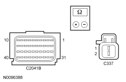 - Are the resistances less than 0.5 ohm?
| Yes
GO to
G7
.
No
REPAIR circuit CR106 (VT/GY) or RR106 (YE/OG).
Refer to Wiring Diagrams Cell
5
, Connector Repair Procedures for schematic and connector information.
GO to
G17
.
|
|
G7 CHECK THE RIGHT SIDE AIRBAG DEPLOYMENT CONTROL DTC FOR A FAULT STATUS CHANGE (OPEN INDICATED)
|
|
NOTE:
This pinpoint test step will attempt to change the fault reported by the
by inducing a different fault condition. If the fault reported changes, this indicates the
is functioning correctly and is not the source of the fault.
- Connect:
C2041A and C2041B .
- Connect a fused jumper wire between passenger seat side air bag C337-1, circuit CR106 (VT/GY), harness side and C337-2, circuit RR106 (YE/OG), harness side.
- Repower the
.
Do not
prove out the
at this time. Refer to
Supplemental Restraint System (SRS) Depowering and Repowering
in this section.
- Ignition ON.
- Enter the following diagnostic mode on the scan tool: Self Test —
.
- DIAGNOSTIC TIP:
When viewing DTCs with the passenger side air bag circuits shorted together, a low resistance fault would normally be retrieved.
- Did the on-demand DTC change from B0028:13 to B0028:1A?
| Yes
GO to
G11
.
No
GO to
G12
.
|
|
G8 CHECK THE RIGHT SIDE AIRBAG DEPLOYMENT CONTROL DTC FOR A FAULT STATUS CHANGE (SHORT TO GROUND INDICATED)
|
|
NOTE:
This pinpoint test step will attempt to change the fault reported by the
by inducing a different fault condition. If the fault reported changes, this indicates the
is functioning correctly and is not the source of the fault.
- Ignition OFF.
- Depower the
. Refer to
Supplemental Restraint System (SRS) Depowering and Repowering
in this section.
- Disconnect: Passenger Seat Side Air Bag Module C337 .
- Repower the
.
Do not
prove out the
at this time. Refer to
Supplemental Restraint System (SRS) Depowering and Repowering
in this section.
- Ignition ON.
- Enter the following diagnostic mode on the scan tool: Self Test —
.
- DIAGNOSTIC TIP:
When viewing DTCs with the passenger seat side air bag module disconnected, an open circuit fault would normally be retrieved.
- Did the on-demand DTC change from B0028:11 to B0028:13?
| Yes
GO to
G11
.
No
GO to
G9
.
|
|
G9 CHECK THE PASSENGER SEAT SIDE AIR BAG CIRCUITS FOR A SHORT TO GROUND
|
|
- Ignition OFF.
- Depower the
. Refer to
Supplemental Restraint System (SRS) Depowering and Repowering
in this section.
- Disconnect:
C2041A and C2041B .
- Measure the resistance between passenger seat side air bag:
- C337-1, circuit CR106 (VT/GY), harness side and ground.
- C337-2, circuit RR106 (YE/OG), harness side and ground.
- Are the resistances greater than 10,000 ohms?
| Yes
GO to
G12
.
No
REPAIR circuit CR106 (VT/GY) or RR106 (YE/OG).
Refer to Wiring Diagrams Cell
5
, Connector Repair Procedures for schematic and connector information.
GO to
G17
.
|
|
G10 CHECK THE PASSENGER SEAT SIDE AIR BAG CIRCUITS FOR A SHORT TO VOLTAGE
|
|
| Yes
REPAIR circuit CR106 (VT/GY) or RR106 (YE/OG).
Refer to Wiring Diagrams Cell
5
, Connector Repair Procedures for schematic and connector information.
GO to
G17
.
No
GO to
G12
.
|
|
G11 CONFIRM THE PASSENGER SEAT SIDE AIR BAG MODULE FAULT
|
|
NOTE:
Make sure all restraint system components and the
electrical connectors are connected before carrying out the self-test. If not, DTCs will be recorded.
- Ignition OFF.
- Depower the
. Refer to
Supplemental Restraint System (SRS) Depowering and Repowering
in this section.
- If previously installed, remove the fused jumper wire from the passenger seat side air bag C337.
- Connect: Passenger Seat Side Air Bag Module C337 .
- Connect:
C2041A and C2041B .
- Repower the
.
Do not
prove out the
at this time. Refer to
Supplemental Restraint System (SRS) Depowering and Repowering
in this section.
- Ignition ON.
- Enter the following diagnostic mode on the scan tool: Self Test —
.
- Was the original DTC retrieved on-demand during self-test?
| Yes
REMOVE and INSPECT the passenger seat side air bag module wire harness for damage. REFER to
Side Airbag
in this section. If a concern is found, REPAIR the seat side air bag wire harness.
Refer to Wiring Diagrams Cell
5
, Connector Repair Procedures for schematic and connector information.
If a concern
was not
found, INSTALL a new passenger seat side air bag module. REFER to
Side Airbag
in this section. GO to
G17
.
No
In the process of diagnosing the fault, the fault condition has become intermittent.
Do not install any new
components at this time.
components should only be installed when directed to do so in the pinpoint test.
For DTC B0028:13 or B0028:1A, GO to
G13
.
For DTC B0028:11, GO to
G14
.
For DTC B0028:12, GO to
G15
.
|
|
G12 CONFIRM THE
FAULT
|
|
NOTE:
Make sure all restraint system components and the
electrical connectors are connected before carrying out the self-test. If not, DTCs will be recorded.
- Ignition OFF.
- Depower the
. Refer to
Supplemental Restraint System (SRS) Depowering and Repowering
in this section.
- Prior to reconnecting any previously disconnected
component:
- inspect connector(s) (including any in-line connectors) for pushed-out, loose or spread terminals and loose or frayed wire connections at terminals.
- inspect wire harness for any damage, pinched, cut or pierced wires.
- If previously installed, remove the fused jumper wire from the passenger seat side air bag C337.
- Connect: Passenger Seat Side Air Bag Module C337 .
- Connect:
C2041A and C2041B (if previously disconnected) .
- Repower the
.
Do not
prove out the
at this time. Refer to
Supplemental Restraint System (SRS) Depowering and Repowering
in this section.
- Ignition ON.
- Enter the following diagnostic mode on the scan tool: Self Test —
.
- Was the original DTC retrieved on-demand during self-test?
| Yes
INSTALL a new
. REFER to
Restraints Control Module (RCM)
in this section. GO to
G17
.
No
In the process of diagnosing the fault, the fault condition has become intermittent.
Do not install any new
components at this time.
components should only be installed when directed to do so in the pinpoint test.
For DTC B0028:13 or B0028:1A, GO to
G13
.
For DTC B0028:11, GO to
G14
.
For DTC B0028:12, GO to
G15
.
|
|
G13 CHECK THE RIGHT SIDE AIRBAG DEPLOYMENT CONTROL RESISTANCE (DEPLOY_13_R) PID FOR AN INTERMITTENT LOW RESISTANCE OR OPEN CIRCUIT FAULT
|
|
- Enter the following diagnostic mode on the scan tool: DataLogger —
.
- Attempt to recreate the fault by wiggling connectors (including any in-line connectors) and flexing the wire harness frequently.
- Does the PID value read between 1.7 and 2.78 ohms?
| Yes
The fault is not present and cannot be recreated at this time.
Do not install any new
components at this time.
components should only be installed when directed to do so in the pinpoint test.
GO to
G16
.
No
DEPOWER the
and REPAIR as necessary.
Refer to Wiring Diagrams Cell
5
, Connector Repair Procedures for schematic and connector information.
GO to
G17
.
|
|
G14 CHECK THE RIGHT SIDE AIRBAG DEPLOYMENT CONTROL FOR AN INTERMITTENT SHORT TO GROUND FAULT
|
|
- Ignition ON.
- Attempt to recreate the fault by wiggling connectors (including any in-line connectors) and flexing the wire harness frequently.
- Enter the following diagnostic mode on the scan tool: Self Test —
.
- Was DTC B0028:11 retrieved on-demand during self-test?
| Yes
DEPOWER the
and REPAIR as necessary.
Refer to Wiring Diagrams Cell
5
, Connector Repair Procedures for schematic and connector information.
GO to
G17
.
No
The fault is not present and cannot be recreated at this time.
Do not install any new
components at this time.
components should only be installed when directed to do so in the pinpoint test.
GO to
G16
.
|
|
G15 CHECK THE RIGHT SIDE AIRBAG DEPLOYMENT CONTROL FOR AN INTERMITTENT SHORT TO BATTERY FAULT
|
|
| Yes
DEPOWER the
and REPAIR as necessary.
Refer to Wiring Diagrams Cell
5
, Connector Repair Procedures for schematic and connector information.
GO to
G17
.
No
The fault is not present and cannot be recreated at this time.
Do not install any new
components at this time.
components should only be installed when directed to do so in the pinpoint test.
GO to
G16
.
|
|
G16 CHECK THE HARNESS AND CONNECTORS
|
|
- Ignition OFF.
- Depower the
. Refer to
Supplemental Restraint System (SRS) Depowering and Repowering
in this section.
- Disconnect the passenger seat side air bag module C337:
- inspect connector(s) (including any in-line connectors) for corrosion, loose or spread terminals and loose or frayed wire connections at terminals.
- inspect wire harness for any damage, pinched, cut or pierced wires.
- Were any concerns found?
| Yes
REPAIR as necessary.
Refer to Wiring Diagrams Cell
5
, Connector Repair Procedures for schematic and connector information.
GO to
G17
.
No
The fault is not present and cannot be recreated at this time.
Do not install any new
components at this time.
components should only be installed when directed to do so in the pinpoint test.
GO to
G17
.
|
|
G17 CHECK FOR ADDITIONAL
DTCs
|
|
- Ignition OFF.
- WARNING: Turn the ignition OFF and wait one minute to deplete the backup power supply. Failure to follow this instruction may result in serious personal injury or death in the event of an accidental deployment.
- Reconnect all
components (if previously disconnected).
- If previously directed to depower the
, repower the
.
Do not
prove out the
at this time. Refer to
Supplemental Restraint System (SRS) Depowering and Repowering
in this section.
- Ignition ON.
- Enter the following diagnostic mode on the scan tool: Self Test — Restraints .
- NOTE:
When selecting Restraints from the Self Test menu, DTCs will be retrieved from the
and
.
- Are any
and/or
DTCs retrieved on-demand during self-test?
| Yes
Do not clear any DTCs until all DTCs have been resolved. GO to the DTC Charts in this section for pinpoint test direction.
No
CLEAR all
and
. PROVE OUT the
. The repair is complete. RETURN the vehicle to the customer.
|
Pinpoint Test H: DTCs B0050:11, B0050:12, B0050:13 and B0050:1D
Refer to Wiring Diagrams Cell
46
, Supplemental Restraint System for schematic and connector information.
Normal Operation
The Restraints Control Module (RCM) monitors the driver safety belt buckle switch and circuits for the following faults:
- Open circuit
- Short to voltage
- Short to ground
- Current out of range
- Faulted driver safety belt buckle switch
If a fault is detected, the
will store DTC B0050:11, B0050:12, B0050:13 or B0050:1D in memory and will send a message to the Instrument Panel Cluster (IPC) to illuminate the air bag warning indicator.
| DTC Description
| Fault Trigger Condition
|
|---|
- B0050:11 — Driver Seatbelt Sensor: Circuit Short to Ground
| When the
senses a short to ground on the driver safety belt buckle switch circuit, a fault will be indicated.
|
- B0050:12 — Driver Seatbelt Sensor: Circuit Short to Battery
| When the
senses a short to voltage on the driver safety belt buckle switch circuit, a fault will be indicated.
|
- B0050:13 — Driver Seatbelt Sensor: Circuit Open
| When the
senses an open on either driver safety belt buckle switch circuit, a fault will be indicated.
|
- B0050:1D — Driver Seatbelt Sensor: Circuit Current Out of Range
| When the
senses current out of an acceptable range between the driver safety belt buckle switch circuits, a fault will be indicated.
|
This pinpoint test is intended to diagnose the following:
- Wiring, terminals or connectors
- Driver safety belt buckle and pretensioner
PINPOINT TEST H: DTCs B0050:11, B0050:12, B0050:13 AND B0050:1D
WARNING: Never probe the electrical connectors on airbag, Safety Canopy or side air curtain assemblies. Failure to follow this instruction may result in the accidental deployment of these assemblies, which increases the risk of serious personal injury or death.
WARNING: Never disassemble or tamper with seat belt deployable components, including pretensioners, load limiters and inflators. Never back probe deployable device electrical connectors. Tampering or back probing may cause an accidental deployment and result in personal injury or death.
NOTICE:
Use the correct probe adapter(s) from the Flex Probe Kit when taking measurements. Failure to use the correct probe adapter(s) may damage the connector.
Most faults are due to connector and/or wiring concerns. Carry out a thorough inspection and verification before proceeding with the pinpoint test.
NOTE:
Supplemental Restraint System (SRS) components should only be disconnected or reconnected when instructed to do so within a pinpoint test step. Failure to follow this instruction may result in incorrect diagnosis of the
.
NOTE:
Always make sure the correct
component is being installed. Parts released for other vehicles may not be compatible even if they appear physically similar. Check the part number listed in the Ford Catalog Advantage™ or equivalent to make sure the correct component is being installed. If an incorrect
component is installed, DTCs may set.
NOTE:
The
must be fully operational and free of faults before releasing the vehicle to the customer.
| Test Step
| Result / Action to Take
|
|---|
|
H1 RETRIEVE
DTCs
|
|
- Enter the following diagnostic mode on the scan tool: Self Test —
.
- Was DTC B0050:11, B0050:12, B0050:13 or B0050:1D retrieved on-demand during self-test?
| Yes
This fault cannot be cleared until it is corrected and the DTC is no longer retrieved on-demand during self-test.
For DTC B0050:11 or B0050:1D, GO to
H2
.
For DTC B0050:12, GO to
H4
.
For DTC B0050:13, GO to
H5
.
No
This is an intermittent fault when present as a Continuous Memory Diagnostic Trouble Code (CMDTC) only. GO to
H10
.
|
|
H2 CHECK THE DRIVER SEATBELT SENSOR DTC FOR A FAULT STATUS CHANGE (SHORT TO GROUND OR CURRENT OUT OF RANGE INDICATED)
|
|
NOTE:
This pinpoint test step will attempt to change the fault reported by the
by inducing a different fault condition. If the fault reported changes, this indicates the
is functioning correctly and is not the source of the fault.
- Ignition OFF.
- WARNING: Turn the ignition OFF and wait one minute to deplete the backup power supply. Failure to follow this instruction may result in serious personal injury or death in the event of an accidental deployment.
- Disconnect: Driver Safety Belt Buckle Switch C323 .
- Ignition ON.
- Enter the following diagnostic mode on the scan tool: Self Test —
.
- DIAGNOSTIC TIP:
When viewing DTCs with the driver safety belt buckle switch disconnected, an open circuit fault would normally be retrieved.
- Did the on-demand DTC change from B0050:11 or B0050:1D to B0050:13?
| Yes
GO to
H8
.
No
For DTC B0050:11, GO to
H3
.
For DTC B0050:1D, GO to
H9
.
|
|
H3 CHECK THE DRIVER SAFETY BELT BUCKLE SWITCH CIRCUIT FOR A SHORT TO GROUND
|
|
- Ignition OFF.
- Depower the
. Refer to
Supplemental Restraint System (SRS) Depowering and Repowering
in this section.
- Disconnect:
C2041A and C2041B .
- Measure the resistance between driver safety belt buckle switch C323-2, circuit CR201 (GN/BU), harness side and ground.
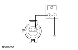 - Is the resistance greater than 10,000 ohms?
| Yes
GO to
H9
.
No
REPAIR circuit CR201 (GN/BU).
Refer to Wiring Diagrams Cell
5
, Connector Repair Procedures for schematic and connector information.
GO to
H11
.
|
|
H4 CHECK THE DRIVER SAFETY BELT BUCKLE SWITCH CIRCUIT FOR A SHORT TO VOLTAGE
|
|
| Yes
REPAIR circuit CR201 (GN/BU).
Refer to Wiring Diagrams Cell
5
, Connector Repair Procedures for schematic and connector information.
GO to
H11
.
No
GO to
H9
.
|
|
H5 CHECK THE DRIVER SEATBELT SENSOR DTC FOR A FAULT STATUS CHANGE (OPEN INDICATED)
|
|
NOTE:
This pinpoint test step will attempt to change the fault reported by the
by inducing a different fault condition. If the fault reported changes, this indicates the
is functioning correctly and is not the source of the fault.
- Ignition OFF.
- Depower the
. Refer to
Supplemental Restraint System (SRS) Depowering and Repowering
in this section.
- Disconnect: Driver Seat Side Air Bag Module C367 .
- Disconnect: Driver Safety Belt Buckle Switch C323 .
- Connect a fused jumper wire between driver safety belt buckle switch C323-2, circuit CR201 (GN/BU), harness side and C323-1, circuit GD138 (BK/WH), harness side.
- Repower the
.
Do not
prove out the
at this time. Refer to
Supplemental Restraint System (SRS) Depowering and Repowering
in this section.
- Enter the following diagnostic mode on the scan tool: Self Test —
.
- DIAGNOSTIC TIP:
When viewing DTCs with the driver safety belt buckle switch circuits shorted together, a short to ground fault would normally be retrieved.
- Did the on-demand DTC change from B0050:13 to B0050:11?
| Yes
GO to
H8
.
No
GO to
H6
.
|
|
H6 CHECK THE DRIVER SAFETY BELT BUCKLE SWITCH CIRCUIT FOR AN OPEN
|
|
- Ignition OFF.
- Depower the
. Refer to
Supplemental Restraint System (SRS) Depowering and Repowering
in this section.
- Disconnect:
C2041A and C2041B .
- Remove the fused jumper wire from the driver safety belt buckle switch connector.
- Measure the resistance between
C2041B-34, circuit CR201 (GN/BU), harness side and driver safety belt buckle switch C323-2, circuit CR201 (GN/BU), harness side.
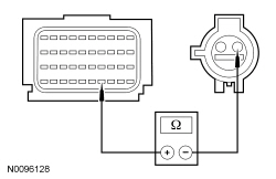 - Is the resistance less than 0.5 ohm?
| Yes
GO to
H7
.
No
REPAIR circuit CR201 (GN/BU).
Refer to Wiring Diagrams Cell
5
, Connector Repair Procedures for schematic and connector information.
GO to
H11
.
|
|
H7 CHECK THE DRIVER SAFETY BELT BUCKLE SWITCH GROUND CIRCUIT FOR AN OPEN
|
|
- Measure the resistance between driver safety belt buckle switch C323-1, circuit GD138 (BK/WH), harness side and ground.
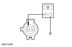 - Is the resistance less than 5 ohms?
| Yes
GO to
H9
.
No
REPAIR circuit GD138 (BK/WH).
Refer to Wiring Diagrams Cell
5
, Connector Repair Procedures for schematic and connector information.
GO to
H11
.
|
|
H8 CONFIRM THE DRIVER SAFETY BELT BUCKLE SWITCH FAULT
|
|
NOTE:
Make sure all restraint system components and the
electrical connectors are connected before carrying out the self-test. If not, DTCs will be recorded.
- Ignition OFF.
- Depower the
. Refer to
Supplemental Restraint System (SRS) Depowering and Repowering
in this section.
- If previously installed, remove the fused jumper wire from driver safety belt buckle switch C323.
- Prior to reconnecting any previously disconnected
component:
- inspect connector(s) (including any in-line connectors) for pushed-out, loose or spread terminals and loose or frayed wire connections at terminals.
- inspect wire harness for any damage, pinched, cut or pierced wires.
- Connect: All Previously Disconnected Component(s)/Connector(s) .
- Repower the
.
Do not
prove out the
at this time. Refer to
Supplemental Restraint System (SRS) Depowering and Repowering
in this section.
- Ignition ON.
- Enter the following diagnostic mode on the scan tool: Self Test —
.
- Was the original DTC retrieved on-demand during self-test?
| Yes
INSTALL a new driver safety belt buckle. REFER to
Section 501-20A
. GO to
H11
.
No
In the process of diagnosing the fault, the fault condition has become intermittent.
Do not install any new
components at this time.
components should only be installed when directed to do so in the pinpoint test.
GO to
H10
.
|
|
H9 CONFIRM THE
FAULT
|
|
NOTE:
Make sure all restraint system components and the
electrical connectors are connected before carrying out the self-test. If not, DTCs will be recorded.
- Ignition OFF.
- Depower the
. Refer to
Supplemental Restraint System (SRS) Depowering and Repowering
in this section.
- Prior to reconnecting any previously disconnected
component:
- inspect connector(s) (including any in-line connectors) for pushed-out, loose or spread terminals and loose or frayed wire connections at terminals.
- inspect wire harness for any damage, pinched, cut or pierced wires.
- Connect: All Previously Disconnected Component(s)/Connector(s) .
- Connect:
C2041A and C2041B (if previously disconnected) .
- Repower the
.
Do not
prove out the
at this time. Refer to
Supplemental Restraint System (SRS) Depowering and Repowering
in this section.
- Ignition ON.
- Enter the following diagnostic mode on the scan tool: Self Test —
.
- Was the original DTC retrieved on-demand during self-test?
| Yes
INSTALL a new
. REFER to
Restraints Control Module (RCM)
in this section. GO to
H11
.
No
In the process of diagnosing the fault, the fault condition has become intermittent.
Do not install any new
components at this time.
components should only be installed when directed to do so in the pinpoint test.
GO to
H10
.
|
|
H10 CHECK FOR AN INTERMITTENT FAULT
|
|
| Yes
This fault cannot be cleared until it is corrected and the DTC is no longer retrieved on-demand during self-test.
For DTC B0050:11 or B0050:1D, GO to
H2
.
For DTC B0050:12, GO to
H4
.
For DTC B0050:13, GO to
H5
.
No
The fault is not present and cannot be recreated at this time.
Do not install any new
components at this time.
components should only be installed when directed to do so in the pinpoint test.
GO to
H11
.
|
|
H11 CHECK FOR ADDITIONAL
DTCs
|
|
- Ignition OFF.
- WARNING: Turn the ignition OFF and wait one minute to deplete the backup power supply. Failure to follow this instruction may result in serious personal injury or death in the event of an accidental deployment.
- Reconnect all
components (if previously disconnected).
- If previously directed to depower the
, repower the
.
Do not
prove out the
at this time. Refer to
Supplemental Restraint System (SRS) Depowering and Repowering
in this section.
- Ignition ON.
- Enter the following diagnostic mode on the scan tool: Self Test — Restraints .
- NOTE:
When selecting Restraints from the Self Test menu, DTCs will be retrieved from the
and
.
- Are any
and/or
DTCs retrieved on-demand during self-test?
| Yes
Do not clear any DTCs until all DTCs have been resolved. GO to the DTC Charts in this section for pinpoint test direction.
No
CLEAR all
and
. PROVE OUT the
. The repair is complete. RETURN the vehicle to the customer.
|
Pinpoint Test I: DTCs B0052:11, B0052:12, B0052:13 and B0052:1D
Refer to Wiring Diagrams Cell
46
, Supplemental Restraint System for schematic and connector information.
Normal Operation
The Restraints Control Module (RCM) monitors the passenger safety belt buckle switch and circuits for the following faults:
- Open circuit
- Short to voltage
- Short to ground
- Current out of range
- Faulted passenger safety belt buckle switch
If a fault is detected, the
will store DTC B0052:11, B0052:12, B0052:13 or B0052:1D in memory and send a message to the Instrument Panel Cluster (IPC) to illuminate the air bag warning indicator.
| DTC Description
| Fault Trigger Condition
|
|---|
- B0052:11 — Passenger Seatbelt Sensor: Circuit Short to Ground
| When the
senses a short to ground on the passenger safety belt buckle switch circuit, a fault will be indicated.
|
- B0052:12 — Passenger Seatbelt Sensor: Circuit Short to Battery
| When the
senses a short to voltage on the passenger safety belt buckle switch circuit, a fault will be indicated.
|
- B0052:13 — Passenger Seatbelt Sensor: Circuit Open
| When the
senses an open on either passenger safety belt buckle switch circuit, a fault will be indicated.
|
- B0052:1D — Passenger Seatbelt Sensor: Circuit Current Out of Range
| When the
senses current out of an acceptable range between the passenger safety belt buckle switch circuits, a fault will be indicated.
|
This pinpoint test is intended to diagnose the following:
- Wiring, terminals or connectors
- Passenger safety belt buckle and pretensioner
PINPOINT TEST I: DTCs B0052:11, B0052:12, B0052:13 AND B0052:1D
WARNING: Never disassemble or tamper with seat belt deployable components, including pretensioners, load limiters and inflators. Never back probe deployable device electrical connectors. Tampering or back probing may cause an accidental deployment and result in personal injury or death.
WARNING: Never probe the electrical connectors on airbag, Safety Canopy or side air curtain assemblies. Failure to follow this instruction may result in the accidental deployment of these assemblies, which increases the risk of serious personal injury or death.
NOTICE:
Use the correct probe adapter(s) from the Flex Probe Kit when taking measurements. Failure to use the correct probe adapter(s) may damage the connector.
Most faults are due to connector and/or wiring concerns. Carry out a thorough inspection and verification before proceeding with the pinpoint test.
NOTE:
Supplemental Restraint System (SRS) components should only be disconnected or reconnected when instructed to do so within a pinpoint test step. Failure to follow this instruction may result in incorrect diagnosis of the
.
NOTE:
Always make sure the correct
component is being installed. Parts released for other vehicles may not be compatible even if they appear physically similar. Check the part number listed in the Ford Catalog Advantage™ or equivalent to make sure the correct component is being installed. If an incorrect
component is installed, DTCs may set.
NOTE:
The
must be fully operational and free of faults before releasing the vehicle to the customer.
| Test Step
| Result / Action to Take
|
|---|
|
I1 RETRIEVE
DTCs
|
|
- Enter the following diagnostic mode on the scan tool: Self Test —
.
- Was DTC B0052:11, B0052:12, B0052:13 or B0052:1D retrieved on-demand during self-test?
| Yes
This fault cannot be cleared until it is corrected and the DTC is no longer retrieved on-demand during self-test.
For DTC B0052:11 or B0052:1D, GO to
I2
.
For DTC B0052:12, GO to
I4
.
For DTC B0052:13, GO to
I5
.
No
This is an intermittent fault when present as a Continuous Memory Diagnostic Trouble Code (CMDTC) only. GO to
I10
.
|
|
I2 CHECK THE PASSENGER SEATBELT SENSOR DTC FOR A FAULT STATUS CHANGE (SHORT TO GROUND OR CURRENT OUT OF RANGE INDICATED)
|
|
NOTE:
This pinpoint test step will attempt to change the fault reported by the
by inducing a different fault condition. If the fault reported changes, this indicates the
is functioning correctly and is not the source of the fault.
- Ignition OFF.
- WARNING: Turn the ignition OFF and wait one minute to deplete the backup power supply. Failure to follow this instruction may result in serious personal injury or death in the event of an accidental deployment.
- Disconnect: Passenger Safety Belt Buckle Switch C3066 .
- Ignition ON.
- Enter the following diagnostic mode on the scan tool: Self Test —
.
- DIAGNOSTIC TIP:
When viewing DTCs with the passenger safety belt buckle switch disconnected, an open circuit fault would normally be retrieved.
- Did the on-demand DTC change from B0052:11 or B0052:1D to B0052:13?
| Yes
GO to
I8
.
No
For DTC B0052:11, GO to
I3
.
For DTC B0052:1D, GO to
I9
.
|
|
I3 CHECK THE PASSENGER SAFETY BELT BUCKLE SWITCH CIRCUIT FOR A SHORT TO GROUND
|
|
- Ignition OFF.
- Depower the
. Refer to
Supplemental Restraint System (SRS) Depowering and Repowering
in this section.
- Disconnect:
C2041A and C2041B .
- Measure the resistance between passenger safety belt buckle switch C3066-2, circuit CR203 (GY/VT), harness side and ground.
- Is the resistance greater than 10,000 ohms?
| Yes
GO to
I9
.
No
REPAIR circuit CR203 (GY/VT).
Refer to Wiring Diagrams Cell
5
, Connector Repair Procedures for schematic and connector information.
GO to
I11
.
|
|
I4 CHECK THE PASSENGER SAFETY BELT BUCKLE SWITCH CIRCUIT FOR A SHORT TO VOLTAGE
|
|
| Yes
REPAIR circuit CR203 (GY/VT).
Refer to Wiring Diagrams Cell
5
, Connector Repair Procedures for schematic and connector information.
GO to
I11
.
No
GO to
I9
.
|
|
I5 CHECK THE PASSENGER SEATBELT SENSOR DTC FOR A FAULT STATUS CHANGE (OPEN INDICATED)
|
|
NOTE:
This pinpoint test step will attempt to change the fault reported by the
by inducing a different fault condition. If the fault reported changes, this indicates the
is functioning correctly and is not the source of the fault.
- Ignition OFF.
- Depower the
. Refer to
Supplemental Restraint System (SRS) Depowering and Repowering
in this section.
- Disconnect: Passenger Seat Side Air Bag Module C337 .
- Disconnect: Passenger Safety Belt Buckle Switch C3066 .
- Connect a fused jumper wire between passenger safety belt buckle switch C3066-2, circuit CR203 (GY/VT), harness side and C3066-1, circuit GD138 (BK/WH), harness side.
- Repower the
.
Do not
prove out the
at this time. Refer to
Supplemental Restraint System (SRS) Depowering and Repowering
in this section.
- Ignition ON.
- Enter the following diagnostic mode on the scan tool: Self Test —
.
- DIAGNOSTIC TIP:
When viewing DTCs with the passenger safety belt buckle switch circuits shorted together, a short to ground fault would normally be retrieved.
- Did the on-demand DTC change from B0052:13 to B0052:11?
| Yes
GO to
I8
.
No
GO to
I6
.
|
|
I6 CHECK THE PASSENGER SAFETY BELT BUCKLE SWITCH CIRCUIT FOR AN OPEN
|
|
- Ignition OFF.
- Depower the
. Refer to
Supplemental Restraint System (SRS) Depowering and Repowering
in this section.
- Disconnect:
C2041A and C2041B .
- Remove the fused jumper wire from the passenger safety belt buckle switch connector.
- Measure the resistance between
C2041B-33, circuit CR203 (GY/VT), harness side and the passenger safety belt buckle switch C3066-2, circuit CR203 (GY/VT), harness side.
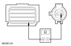 - Is the resistance less than 0.5 ohm?
| Yes
GO to
I7
.
No
REPAIR circuit CR203 (GY/VT).
Refer to Wiring Diagrams Cell
5
, Connector Repair Procedures for schematic and connector information.
GO to
I11
.
|
|
I7 CHECK THE PASSENGER SAFETY BELT BUCKLE SWITCH GROUND CIRCUIT FOR AN OPEN
|
|
- Measure the resistance between passenger safety belt buckle switch C3066-1, circuit GD138 (BK/WH), harness side and ground.
- Is the resistance less than 5 ohms?
| Yes
GO to
I9
.
No
REPAIR circuit GD138 (BK/WH).
Refer to Wiring Diagrams Cell
5
, Connector Repair Procedures for schematic and connector information.
GO to
I11
.
|
|
I8 CONFIRM THE PASSENGER SAFETY BELT BUCKLE SWITCH FAULT
|
|
NOTE:
Make sure all restraint system components and the
electrical connectors are connected before carrying out the self-test. If not, DTCs will be recorded.
- Ignition OFF.
- Depower the
. Refer to
Supplemental Restraint System (SRS) Depowering and Repowering
in this section.
- If previously installed, remove the fused jumper wire from the passenger safety belt buckle switch C3066.
- Prior to reconnecting any previously disconnected
component:
- inspect connector(s) (including any in-line connectors) for pushed-out, loose or spread terminals and loose or frayed wire connections at terminals.
- inspect wire harness for any damage, pinched, cut or pierced wires.
- Connect: All Previously Disconnected Component(s)/Connector(s) .
- Repower the
.
Do not
prove out the
at this time. Refer to
Supplemental Restraint System (SRS) Depowering and Repowering
in this section.
- Ignition ON.
- Enter the following diagnostic mode on the scan tool: Self Test —
.
- Was the original DTC retrieved on-demand during self-test?
| Yes
INSTALL a new passenger safety belt buckle. REFER to
Section 501-20A
. GO to
I11
.
No
In the process of diagnosing the fault, the fault condition has become intermittent.
Do not install any new
components at this time.
components should only be installed when directed to do so in the pinpoint test.
GO to
I10
.
|
|
I9 CONFIRM THE
FAULT
|
|
NOTE:
Make sure all restraint system components and the
electrical connectors are connected before carrying out the self-test. If not, DTCs will be recorded.
- Ignition OFF.
- Depower the
. Refer to
Supplemental Restraint System (SRS) Depowering and Repowering
in this section.
- Prior to reconnecting any previously disconnected
component:
- inspect connector(s) (including any in-line connectors) for pushed-out, loose or spread terminals and loose or frayed wire connections at terminals.
- inspect wire harness for any damage, pinched, cut or pierced wires.
- Connect: All Previously Disconnected Component(s)/Connector(s) .
- Repower the
.
Do not
prove out the
at this time. Refer to
Supplemental Restraint System (SRS) Depowering and Repowering
in this section.
- Ignition ON.
- Enter the following diagnostic mode on the scan tool: Self Test —
.
- Was the original DTC retrieved on-demand during self-test?
| Yes
INSTALL a new
. REFER to
Restraints Control Module (RCM)
in this section. GO to
I11
.
No
In the process of diagnosing the fault, the fault condition has become intermittent.
Do not install any new
components at this time.
components should only be installed when directed to do so in the pinpoint test.
GO to
I10
.
|
|
I10 CHECK FOR AN INTERMITTENT FAULT
|
|
| Yes
This fault cannot be cleared until it is corrected and the DTC is no longer retrieved on-demand during self-test.
For DTC B0052:11 or B0052:1D, GO to
I2
.
For DTC B0052:12, GO to
I4
.
For DTC B0052:13, GO to
I5
.
No
The fault is not present and cannot be recreated at this time.
Do not install any new
components at this time.
components should only be installed when directed to do so in the pinpoint test.
GO to
I11
.
|
|
I11 CHECK FOR ADDITIONAL
DTCs
|
|
- Ignition OFF.
- WARNING: Turn the ignition OFF and wait one minute to deplete the backup power supply. Failure to follow this instruction may result in serious personal injury or death in the event of an accidental deployment.
- Reconnect all
components (if previously disconnected).
- If previously directed to depower the
, repower the
.
Do not
prove out the
at this time. Refer to
Supplemental Restraint System (SRS) Depowering and Repowering
in this section.
- Ignition ON.
- Enter the following diagnostic mode on the scan tool: Self Test — Restraints .
- NOTE:
When selecting Restraints from the Self Test menu, DTCs will be retrieved from the
and
.
- Are any
and/or
DTCs retrieved on-demand during self-test?
| Yes
Do not clear any DTCs until all DTCs have been resolved. GO to the DTC Charts in this section for pinpoint test direction.
No
CLEAR all
and
. PROVE OUT the
. The repair is complete. RETURN the vehicle to the customer.
|
Pinpoint Test J: DTCs B0090:11 or B0090:93
Refer to Wiring Diagrams Cell
46
, Supplemental Restraint System for schematic and connector information.
Normal Operation
The Restraints Control Module (RCM) monitors the front impact severity sensor and circuits for the following faults:
- Open circuit
- Short to voltage
- Short to ground
- Incorrect sensor installed
- Faulted front impact severity sensor
If a fault is detected, the
will store DTC B0090:11 or B0090:93 in memory and send a message to the Instrument Panel Cluster (IPC) to illuminate the air bag warning indicator.
- DTC B0090:11 (Left Frontal Restraints Sensor: Circuit Short to Ground) — When the
senses a short to ground on the feed circuit of the front impact severity sensor, a fault will be indicated.
- DTC B0090:93 (Left Frontal Restraints Sensor: No Operation) — When the
senses a faulted sensor, a short to voltage on the feed or return circuit, or an open feed or return circuit, a fault will be indicated.
This pinpoint test is intended to diagnose the following:
- Wiring, terminals or connectors
- Front impact severity sensor
PINPOINT TEST J: DTCs B0090:11 OR B0090:93
NOTICE:
Use the correct probe adapter(s) from the Flex Probe Kit when taking measurements. Failure to use the correct probe adapter(s) may damage the connector.
Most faults are due to connector and/or wiring concerns. Carry out a thorough inspection and verification before proceeding with the pinpoint test.
NOTE:
Supplemental Restraint System (SRS) components should only be disconnected or reconnected when instructed to do so within a pinpoint test step. Failure to follow this instruction may result in incorrect diagnosis of the
.
NOTE:
The
must be fully operational and free of faults before releasing the vehicle to the customer.
NOTE:
Always make sure the correct
component is being installed. Parts released for other vehicles may not be compatible even if they appear physically similar. Check the part number listed in the Master Parts Catalog to make sure the correct component is being installed. If an incorrect
component is installed, DTCs may set.
NOTE:
Do not probe any impact sensor. The impact sensor cannot be tested using a multi-meter.
| Test Step
| Result / Action to Take
|
|---|
|
J1 RETRIEVE THE
DTCs
|
|
- Enter the following diagnostic mode on the scan tool: Self Test —
.
- Was DTC B0090:11 or B0090:93 retrieved on-demand during self-test?
| Yes
This fault cannot be cleared until it is corrected and the DTC is no longer retrieved on-demand during self-test.
For DTC B0090:11, GO to
J2
.
For DTC B0090:93, GO to
J5
.
No
The fault is intermittent when present as a Continuous Memory Diagnostic Trouble Code (CMDTC) only. GO to
J10
.
|
|
J2 CHECK THE LEFT FRONTAL RESTRAINTS SENSOR DTC FOR FAULT STATUS CHANGE (SHORT TO GROUND INDICATED)
|
|
NOTE:
This pinpoint test step will attempt to change the fault reported by the
by inducing a different fault condition. If the fault reported changes, this indicates the
is functioning correctly and is not the source of the fault.
- Ignition OFF.
- Depower the
. Refer to
Supplemental Restraint System (SRS) Depowering and Repowering
in this section.
- Disconnect: Front Impact Severity Sensor C1598 .
- Repower the
.
Do not
prove out the
at this time. Refer to
Supplemental Restraint System (SRS) Depowering and Repowering
in this section.
- Ignition ON.
- Enter the following diagnostic mode on the scan tool: Self Test —
.
- Did the on-demand DTC change from B0090:11 to B0090:93?
| Yes
INSTALL a new front impact severity sensor. REFER to
Front Impact Severity Sensor
in this section. GO to
J11
.
No
GO to
J3
.
|
|
J3 CHECK FRONT IMPACT SEVERITY SENSOR CIRCUIT FOR A SHORT TO GROUND
|
|
- Ignition OFF.
- Depower the
. Refer to
Supplemental Restraint System (SRS) Depowering and Repowering
in this section.
- Disconnect:
C2041A and C2041B.
- Measure the resistance between front impact severity sensor C1598-1, circuit VR213 (VT/GN), harness side and ground.
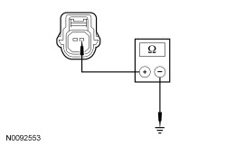 - Is the resistance greater than 10,000 ohms?
| Yes
GO to
J4
.
No
REPAIR circuit VR213 (VT/GN).
Refer to Wiring Diagrams Cell
5
, Connector Repair Procedures for schematic and connector information.
GO to
J11
.
|
|
J4 CHECK FOR A SHORT BETWEEN FRONT IMPACT SEVERITY SENSOR CIRCUITS
|
|
- Measure the resistance between front impact severity sensor C1598-1, circuit VR213 (VT/GN), harness side and C1598-2, circuit RR129 (YE/GY), harness side.
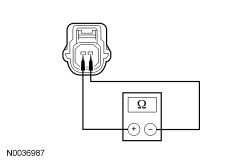 - Is the resistance greater than 10,000 ohms?
| Yes
GO to
J9
.
No
REPAIR circuits VR213 (VT/GN) and RR129 (YE/GY).
Refer to Wiring Diagrams Cell
5
, Connector Repair Procedures for schematic and connector information.
GO to
J11
.
|
|
J5 CHECK THE LEFT FRONT IMPACT SEVERITY SENSOR AND
CONNECTIONS (NO OPERATION INDICATED)
|
|
- Ignition OFF.
- WARNING: Turn the ignition OFF and wait one minute to deplete the backup power supply. Failure to follow this instruction may result in serious personal injury or death in the event of an accidental deployment.
- Inspect the front impact severity sensor connector to be fully seated and locked. Seat and lock connector as necessary.
- Gain access to the
and inspect C2041A and C2041B to be fully seated and locked. Seat and lock the connector(s) as necessary. Refer to
Restraints Control Module (RCM)
in this section.
- Ignition ON.
- Enter the following diagnostic mode on the scan tool: Self Test —
.
- Was DTC B0090:93 retrieved on-demand during self-test?
| Yes
GO to
J6
.
No
Fault corrected. GO to
J11
.
|
|
J6 CHECK THE FRONT IMPACT SEVERITY SENSOR CIRCUITS FOR A SHORT TO VOLTAGE (NO OPERATION INDICATED)
|
|
| Yes
REPAIR circuit VR213 (VT/GN) or RR129 (YE/GY).
Refer to Wiring Diagrams Cell
5
, Connector Repair Procedures for schematic and connector information.
GO to
J11
.
No
GO to
J7
.
|
|
J7 CHECK THE FRONT IMPACT SEVERITY SENSOR CIRCUITS FOR AN OPEN (NO OPERATION INDICATED)
|
|
- Ignition OFF.
- Depower the
. Refer to
Supplemental Restraint System (SRS) Depowering and Repowering
in this section.
- Measure the resistance between
C2041B, harness side and front impact severity sensor C1598, harness side using the following chart:
| Circuit
| Front Impact Severity Sensor
|
|---|
| C2041B-27
| VR213 (VT/GN)
| C1598-1
| | C2041B-28
| RR129 (YE/GY)
| C1598-2
|
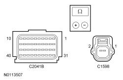 - Are the resistances less than 0.5 ohm?
| Yes
GO to
J8
.
No
REPAIR circuit VR213 (VT/GN) or RR129 (YE/GY).
Refer to Wiring Diagrams Cell
5
, Connector Repair Procedures for schematic and connector information.
GO to
J11
.
|
|
J8 CHECK THE LEFT FRONTAL RESTRAINTS SENSOR DTC FOR A FAULT STATUS CHANGE (NO OPERATION INDICATED)
|
|
NOTE:
This pinpoint test step will attempt to change the fault reported by the
by inducing a different fault condition. If the fault reported changes, this indicates the
is functioning correctly and is not the source of the fault.
- Connect:
C2041A and C2041B .
- Connect a fused jumper wire between front impact severity sensor C1598-1, circuit VR213 (VT/GN), harness side and circuit C1598-2, circuit RR129 (YE/GY), harness side.
- Repower the
.
Do not
prove out the
at this time. Refer to
Supplemental Restraint System (SRS) Depowering and Repowering
in this section.
- Ignition ON.
- Enter the following diagnostic mode on the scan tool: Self Test —
.
- Did the on-demand DTC change from B0090:93 to B0090:11?
| Yes
INSTALL a new front impact severity sensor. REFER to
Front Impact Severity Sensor
in this section. GO to
J11
.
No
GO to
J9
.
|
|
J9 CONFIRM THE
FAULT
|
|
NOTE:
Make sure all restraint system components and the
electrical connectors are connected before carrying out the self-test. If not, DTCs will be recorded.
- Ignition OFF.
- Depower the
. Refer to
Supplemental Restraint System (SRS) Depowering and Repowering
in this section.
- Prior to reconnecting any previously disconnected
component:
- inspect connector(s) (including any in-line connectors) for pushed out, loose or spread terminals and loose or frayed wire connections at terminals.
- inspect wire harness for any damage, pinched, cut or pierced wires.
- Connect:
C2041A and C2041B .
- Connect: Front Impact Severity Sensor C1598 .
- Repower the
.
Do not
prove out the
at this time. Refer to
Supplemental Restraint System (SRS) Depowering and Repowering
in this section.
- Enter the following diagnostic mode on the scan tool: Self Test —
.
- Was the original DTC retrieved on-demand during self-test?
| Yes
INSTALL a new
. REFER to
Restraints Control Module (RCM)
in this section. GO to
J11
.
No
In the process of diagnosing the fault, the fault condition has become intermittent.
Do not install any new
components at this time.
components should only be installed when directed to do so in the pinpoint test.
GO to
J10
.
|
|
J10 CHECK FOR AN INTERMITTENT FAULT
|
|
- Ignition OFF.
- Depower the
. Refer to
Supplemental Restraint System (SRS) Depowering and Repowering
in this section.
- Disconnect: Front Impact Severity Sensor C1598 .
- Disconnect:
C2041A and C2041B .
- Inspect for the following:
- inspect harness and component connectors for pushed out, loose or spread terminals and loose or frayed wire connections at terminals.
- inspect wire harness for any damage, pinched, cut or pierced wires.
- Connect: All Previously Disconnected Component(s)/Connector(s) .
- Repower the
.
Do not
prove out the
at this time. Refer to
Supplemental Restraint System (SRS) Depowering and Repowering
in this section.
- Ignition ON.
- Enter the following diagnostic mode on the scan tool: Self Test —
.
- Was DTC B0090:11 or B0090:93 retrieved on-demand during self-test?
| Yes
This fault cannot be cleared until it is corrected and the DTC is no longer retrieved on-demand during self-test.
For DTC B0090:11, GO to
J2
.
For DTC B0090:93, GO to
J5
.
No
The fault is not present and cannot be recreated at this time.
Do not install any new
components at this time.
components should only be installed when directed to do so in the pinpoint test.
GO to
J11
.
|
|
J11 CHECK FOR ADDITIONAL
DTCs
|
|
- Ignition OFF.
- WARNING: Turn the ignition OFF and wait one minute to deplete the backup power supply. Failure to follow this instruction may result in serious personal injury or death in the event of an accidental deployment.
- Reconnect all
components (if previously disconnected).
- If previously directed to depower the
, repower the
.
Do not
prove out the
at this time. Refer to
Supplemental Restraint System (SRS) Depowering and Repowering
in this section.
- Ignition ON.
- Enter the following diagnostic mode on the scan tool: Self Test — Restraints .
- NOTE:
When selecting Restraints from the Self Test menu, DTCs will be retrieved from the
and Occupant Classification System Module (OCSM).
- Was the original DTC retrieved on-demand during self-test?
| Yes
Do not clear any DTCs until all DTCs have been resolved. GO to the DTC Charts in this section for pinpoint test direction.
No
CLEAR all
and
. PROVE OUT the
. The repair is complete. RETURN the vehicle to the customer.
|
Pinpoint Test K: DTCs B0091:11 or B0091:93
Refer to Wiring Diagrams Cell
46
, Supplemental Restraint System for schematic and connector information.
Normal Operation
The
monitors the driver side impact sensor and circuits for the following faults:
- Open circuit
- Short to voltage
- Short to ground
- Faulted driver front door side impact sensor
If a fault is detected, the
stores DTC B0091:11 or B0091:93 in memory and sends a message to the
to illuminate the air bag warning indicator.
- DTC B0091:11 (Left Side Restraints Sensor 1: Circuit Short to Ground) — A fault is indicated when the
senses a short to ground on the driver front door side impact sensor feed circuit.
- DTC B0091:93 (Left Side Restraints Sensor 1: No Operation) — A fault is indicated when the
senses a faulted driver front door side impact sensor, a short to voltage on the feed or return circuit, or an open on the feed or return circuit.
This pinpoint test is intended to diagnose the following:
- Wiring, terminals or connectors
- Driver front door side impact sensor
PINPOINT TEST K: DTCs B0091:11 OR B0091:93
NOTICE:
Use the correct probe adapter(s) from the Flex Probe Kit when taking measurements. Failure to use the correct probe adapter(s) may damage the connector.
Most faults are due to connector and/or wiring concerns. Carry out a thorough inspection and verification before proceeding with the pinpoint test.
NOTE:
components should only be disconnected or reconnected when instructed to do so within a pinpoint test step. Failure to follow this instruction may result in incorrect diagnosis of the
.
NOTE:
The
must be fully operational and free of faults before releasing the vehicle to the customer.
NOTE:
Always make sure the correct
component is being installed. Parts released for other vehicles may not be compatible even if they appear physically similar. Check the part number listed in the Master Parts Catalog to make sure the correct component is being installed. If an incorrect
component is installed, DTCs may set.
NOTE:
Do not probe any impact sensor. The impact sensor cannot be tested using a multi-meter.
| Test Step
| Result / Action to Take
|
|---|
|
K1 RETRIEVE THE
DTCs
|
|
- Enter the following diagnostic mode on the scan tool: Self Test —
.
- Was DTC B0091:11 or B0091:93 retrieved on-demand during self-test?
| Yes
This fault cannot be cleared until it is corrected and the DTC is no longer retrieved on-demand during self-test.
For DTC B0091:11, GO to
K2
.
For DTC B0091:93, GO to
K5
.
No
The fault is intermittent when present as a
only. GO to
K10
.
|
|
K2 CHECK THE LEFT SIDE RESTRAINTS SENSOR 1 DTC FOR A FAULT STATUS CHANGE (SHORT TO GROUND INDICATED)
|
|
NOTE:
This pinpoint test step attempts to change the fault reported by the
by inducing a different fault condition. If the fault reported changes, this indicates the
is functioning correctly and is not the source of the fault.
- Ignition OFF.
- Depower the
. Refer to
Supplemental Restraint System (SRS) Depowering and Repowering
in this section.
- Disconnect: Driver Front Door Side Impact Sensor C567.
- Repower the
.
Do not
prove out the
at this time. Refer to
Supplemental Restraint System (SRS) Depowering and Repowering
in this section.
- Ignition ON.
- Enter the following diagnostic mode on the scan tool: Self Test —
.
- Did the on-demand DTC change from B0091:11 to B0091:93?
| Yes
INSTALL a new driver front door side impact sensor. REFER to
Side Impact Sensor
in this section. GO to
K11
.
No
GO to
K3
.
|
|
K3 CHECK THE DRIVER FRONT DOOR SIDE IMPACT SENSOR CIRCUIT FOR A SHORT TO GROUND
|
|
- Ignition OFF.
- Depower the
. Refer to
Supplemental Restraint System (SRS) Depowering and Repowering
in this section.
- Disconnect:
C2041A and C2041B.
- Measure the resistance between driver front door side impact sensor C567-1, circuit VR217 (GY/YE), harness side and ground.
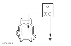 - Is the resistance greater than 10,000 ohms?
| Yes
GO to
K4
.
No
REPAIR the circuit.
Refer to Wiring Diagrams Cell
5
, Connector Repair Procedures for schematic and connector information.
GO to
K11
.
|
|
K4 CHECK FOR A SHORT BETWEEN DRIVER FRONT DOOR SIDE IMPACT SENSOR CIRCUITS
|
|
- Measure the resistance between driver front door side impact sensor C567-1, circuit VR217 (GY/YE), harness side and C567-2, circuit RR131 (VT/GY), harness side.
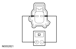 - Is the resistance greater than 10,000 ohms?
| Yes
GO to
K9
.
No
REPAIR the circuits.
Refer to Wiring Diagrams Cell
5
, Connector Repair Procedures for schematic and connector information.
GO to
K11
.
|
|
K5 CHECK THE DRIVER FRONT DOOR SIDE IMPACT SENSOR AND
CONNECTIONS (NO OPERATION INDICATED)
|
|
| Yes
GO to
K6
.
No
Fault corrected. GO to
K11
.
|
|
K6 CHECK THE DRIVER FRONT DOOR SIDE IMPACT SENSOR CIRCUITS FOR A SHORT TO VOLTAGE (NO OPERATION INDICATED)
|
|
| Yes
REPAIR the affected circuit.
Refer to Wiring Diagrams Cell
5
, Connector Repair Procedures for schematic and connector information.
GO to
K11
.
No
GO to
K7
.
|
|
K7 CHECK THE DRIVER FRONT DOOR SIDE IMPACT SENSOR CIRCUITS FOR AN OPEN (NO OPERATION INDICATED)
|
|
- Ignition OFF.
- Depower the
. Refer to
Supplemental Restraint System (SRS) Depowering and Repowering
in this section.
- Measure the resistance between
C2041B, harness side and driver front door side impact sensor C567, harness side using the following chart:
| Circuit
| Driver Front Door Side Impact Sensor
|
|---|
| C2041B-36
| VR217 (GY/YE)
| C567-1
| | C2041B-35
| RR131 (VT/GY)
| C567-2
|
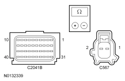 - Are the resistances less than 0.5 ohm?
| Yes
GO to
K8
.
No
REPAIR the affected circuit.
Refer to Wiring Diagrams Cell
5
, Connector Repair Procedures for schematic and connector information.
GO to
K11
.
|
|
K8 CHECK THE LEFT SIDE RESTRAINTS SENSOR 1 DTC FOR A FAULT STATUS CHANGE (NO OPERATION INDICATED)
|
|
NOTE:
This pinpoint test step attempts to change the fault reported by the
by inducing a different fault condition. If the fault reported changes, this indicates the
is functioning correctly and is not the source of the fault.
- Connect:
C2041A and C2041B.
- Connect a fused jumper wire between driver front door side impact sensor C567-1, circuit VR217 (GY/YE), harness side and C567-2 circuit RR131 (VT/GY), harness side.
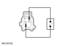 - Repower the
.
Do not
prove out the
at this time. Refer to
Supplemental Restraint System (SRS) Depowering and Repowering
in this section.
- Ignition ON.
- Enter the following diagnostic mode on the scan tool: Self Test —
.
- Did the on-demand DTC change from B0091:93 to B0091:11?
| Yes
INSTALL a new driver front door side impact sensor. REFER to
Side Impact Sensor
in this section. GO to
K11
.
No
GO to
K9
.
|
|
K9 CONFIRM THE
FAULT
|
|
NOTE:
Make sure all restraint system components and the
electrical connectors are connected before carrying out the self-test. If not, DTCs will be recorded.
- Ignition OFF.
- Depower the
. Refer to
Supplemental Restraint System (SRS) Depowering and Repowering
in this section.
- Prior to reconnecting any previously disconnected
component:
- inspect connector(s) (including any in-line connectors) for pushed out, loose or spread terminals and loose or frayed wire connections at terminals.
- inspect wire harness for any damage, pinched, cut or pierced wires.
- Connect:
C2041A and C2041B.
- Connect: Driver Front Door Side Impact Sensor C567.
- Repower the
.
Do not
prove out the
at this time. Refer to
Supplemental Restraint System (SRS) Depowering and Repowering
in this section.
- Enter the following diagnostic mode on the scan tool: Self Test —
.
- Was the original DTC retrieved on-demand during self-test?
| Yes
INSTALL a new
. REFER to
Restraints Control Module (RCM)
in this section. GO to
K11
.
No
In the process of diagnosing the fault, the fault condition has become intermittent.
Do not install any new
components at this time.
components should only be installed when directed to do so in the pinpoint test.
GO to
K10
.
|
|
K10 CHECK FOR AN INTERMITTENT FAULT
|
|
- Ignition OFF.
- Depower the
. Refer to
Supplemental Restraint System (SRS) Depowering and Repowering
in this section.
- Disconnect: Driver Front Door Side Impact Sensor C567.
- Disconnect:
C2041A and C2041B.
- Inspect for the following:
- inspect harness and component connectors for pushed out, loose or spread terminals and loose or frayed wire connections at terminals.
- inspect wire harness for any damage, pinched, cut or pierced wires.
- Connect: All Previously Disconnected Component(s)/Connector(s).
- Repower the
.
Do not
prove out the
at this time. Refer to
Supplemental Restraint System (SRS) Depowering and Repowering
in this section.
- Ignition ON.
- Enter the following diagnostic mode on the scan tool: Self Test —
.
- Was DTC B0091:11 or B0091:93 retrieved on-demand during self-test?
| Yes
The fault condition is now present. This fault cannot be cleared until it is corrected and the DTC is no longer retrieved on-demand during self-test.
For DTC B0091:11, GO to
K2
.
For DTC B0091:93, GO to
K5
.
No
The fault is not present and cannot be recreated at this time.
Do not install any new
components at this time.
components should only be installed when directed to do so in the pinpoint test.
REPAIR any intermittent wiring, terminal or connector concerns found.
Refer to Wiring Diagrams Cell
5
for schematic and connector information.
GO to
K11
.
|
|
K11 CHECK FOR ADDITIONAL
DTCs
|
|
- Ignition OFF.
- WARNING: Turn the ignition OFF and wait one minute to deplete the backup power supply. Failure to follow this instruction may result in serious personal injury or death in the event of an accidental deployment.
- Reconnect all
components (if previously disconnected).
- If previously directed to depower the
, repower the
.
Do not
prove out the
at this time. Refer to
Supplemental Restraint System (SRS) Depowering and Repowering
in this section.
- Ignition ON.
- Enter the following diagnostic mode on the scan tool: Self Test — Restraints.
- NOTE:
When selecting Restraints from the Self Test menu, DTCs are retrieved from the
and
.
- Was the original DTC retrieved on-demand during self-test?
| Yes
Do not clear any DTCs until all DTCs have been resolved. REFER to DTC Charts in this section for pinpoint test direction.
No
CLEAR all
and
. PROVE OUT the
. The repair is complete. RETURN the vehicle to the customer.
|
Pinpoint Test L: DTC B0096:11 or DTC B0096:93
Refer to Wiring Diagrams Cell
46
, Supplemental Restraint System for schematic and connector information.
Normal Operation
The
monitors the passenger front door side impact sensor and circuits for the following faults:
- Open circuit
- Short to voltage
- Short to ground
- Faulted passenger front door side impact sensor
If a fault is detected, the
stores DTC B0096:11 or B0096:93 in memory and sends a message to the
to illuminate the air bag warning indicator.
- DTC B0096:11 (Right Side Restraints Sensor: Circuit Short to Ground) — A fault is indicated when the
senses a short to ground on the passenger front door side impact sensor feed circuit.
- DTC B0096:93 (Right Side Restraints Sensor: No Operation) — A fault is indicated when the
senses a faulted passenger front door side impact sensor, a short to voltage on the feed or return circuit, or an open feed or return circuit.
This pinpoint test is intended to diagnose the following:
- Wiring, terminals or connectors
- Passenger front door side impact sensor
PINPOINT TEST L: DTC B0096:11 OR DTC B0096:93
NOTICE:
Use the correct probe adapter(s) from the Flex Probe Kit when taking measurements. Failure to use the correct probe adapter(s) may damage the connector.
Most faults are due to connector and/or wiring concerns. Carry out a thorough inspection and verification before proceeding with the pinpoint test.
NOTE:
components should only be disconnected or reconnected when instructed to do so within a pinpoint test step. Failure to follow this instruction may result in incorrect diagnosis of the
.
NOTE:
The
must be fully operational and free of faults before releasing the vehicle to the customer.
NOTE:
Always make sure the correct
component is being installed. Parts released for other vehicles may not be compatible even if they appear physically similar. Check the part number listed in the Master Parts Catalog to make sure the correct component is being installed. If an incorrect
component is installed, DTCs may set.
NOTE:
Do not probe any impact sensor. The impact sensor cannot be tested using a multi-meter.
| Test Step
| Result / Action to Take
|
|---|
|
L1 RETRIEVE THE
DTCs
|
|
- Enter the following diagnostic mode on the scan tool: Self Test —
.
- Was DTC B0096:11 or B0096:93 retrieved on-demand during self-test?
| Yes
This fault cannot be cleared until it is corrected and the DTC is no longer retrieved on-demand during self-test.
For DTC B0096:11, GO to
L2
.
For DTC B0096:93, GO to
L5
.
No
The fault is intermittent when present as a
only. GO to
L10
.
|
|
L2 CHECK THE RIGHT SIDE RESTRAINTS SENSOR DTC FOR FAULT STATUS CHANGE (SHORT TO GROUND INDICATED)
|
|
NOTE:
This pinpoint test step will attempt to change the fault reported by the
by inducing a different fault condition. If the fault reported changes, this indicates the
is functioning correctly and is not the source of the fault.
- Ignition OFF.
- Depower the
. Refer to
Supplemental Restraint System (SRS) Depowering and Repowering
in this section.
- Disconnect: Passenger Front Door Side Impact Sensor C644.
- Repower the
.
Do not
prove out the
at this time. Refer to
Supplemental Restraint System (SRS) Depowering and Repowering
in this section.
- Ignition ON.
- Enter the following diagnostic mode on the scan tool: Self Test —
.
- Did the on-demand DTC change from B0096:11 to B0096:93?
| Yes
INSTALL a new passenger front door side impact sensor. REFER to
Side Impact Sensor
in this section. GO to
L11
.
No
GO to
L3
.
|
|
L3 CHECK THE PASSENGER FRONT DOOR SIDE IMPACT SENSOR CIRCUIT FOR A SHORT TO GROUND
|
|
- Ignition OFF.
- Depower the
. Refer to
Supplemental Restraint System (SRS) Depowering and Repowering
in this section.
- Disconnect:
C2041A and C2041B.
- Measure the resistance between passenger front door side impact sensor C644-1, circuit VR218 (YE/OG), harness side and ground.
- Is the resistance greater than 10,000 ohms?
| Yes
GO to
L4
.
No
REPAIR the circuit.
Refer to Wiring Diagrams Cell
5
, Connector Repair Procedures for schematic and connector information.
GO to
L11
.
|
|
L4 CHECK FOR A SHORT BETWEEN PASSENGER FRONT DOOR SIDE IMPACT SENSOR CIRCUITS
|
|
- Measure the resistance between passenger front door side impact sensor C644-1, circuit VR218 (YE/OG), harness side and C644-2, circuit RR132 (BU/WH), harness side.
- Is the resistance greater than 10,000 ohms?
| Yes
GO to
L9
.
No
REPAIR the circuits.
Refer to Wiring Diagrams Cell
5
, Connector Repair Procedures for schematic and connector information.
GO to
L11
.
|
|
L5 CHECK THE PASSENGER FRONT DOOR SIDE IMPACT SENSOR AND
CONNECTIONS (NO OPERATION INDICATED)
|
|
| Yes
GO to
L6
.
No
Fault corrected. GO to
L11
.
|
|
L6 CHECK THE PASSENGER FRONT DOOR SIDE IMPACT SENSOR CIRCUITS FOR A SHORT TO VOLTAGE (NO OPERATION INDICATED)
|
|
| Yes
REPAIR the affected circuit.
Refer to Wiring Diagrams Cell
5
, Connector Repair Procedures for schematic and connector information.
GO to
L11
.
No
GO to
L7
.
|
|
L7 CHECK THE PASSENGER FRONT DOOR SIDE IMPACT SENSOR CIRCUITS FOR AN OPEN (NO OPERATION INDICATED)
|
|
- Ignition OFF.
- Depower the
. Refer to
Supplemental Restraint System (SRS) Depowering and Repowering
in this section.
- Measure the resistance between
C2041B, harness side and passenger front door side impact sensor C644, harness side using the following chart:
| Circuit
| Passenger Front Door Side Impact Sensor
|
|---|
| C2041B-22
| VR218 (YE/OG)
| C644-1
| | C2041B-21
| RR132 (BU/WH)
| C644-2
|
 - Are the resistances less than 0.5 ohm?
| Yes
GO to
L8
.
No
REPAIR the affected circuit.
Refer to Wiring Diagrams Cell
5
, Connector Repair Procedures for schematic and connector information.
GO to
L11
.
|
|
L8 CHECK THE RIGHT SIDE RESTRAINTS SENSOR 1 DTC FOR A FAULT STATUS CHANGE (NO OPERATION INDICATED)
|
|
NOTE:
This pinpoint test step will attempt to change the fault reported by the
by inducing a different fault condition. If the fault reported changes, this indicates the
is functioning correctly and is not the source of the fault.
- Connect:
C2041A and C2041B.
- Connect a fused jumper wire between passenger front door side impact sensor C644-1, circuit VR218 (YE/OG), harness side and C644-2, circuit RR132 (BU/WH), harness side.
- Repower the
.
Do not
prove out the
at this time. Refer to
Supplemental Restraint System (SRS) Depowering and Repowering
in this section.
- Ignition ON.
- Enter the following diagnostic mode on the scan tool: Self Test —
.
- Did the on-demand DTC change from B0096:93 to B0096:11?
| Yes
INSTALL a new passenger front door side impact sensor. REFER to
Side Impact Sensor
in this section. GO to
L11
.
No
GO to
L9
.
|
|
L9 CONFIRM THE
FAULT
|
|
NOTE:
Make sure all restraint system components and the
electrical connectors are connected before carrying out the self-test. If not, DTCs will be recorded.
- Ignition OFF.
- Depower the
. Refer to
Supplemental Restraint System (SRS) Depowering and Repowering
in this section.
- Prior to reconnecting any previously disconnected
component:
- inspect connector(s) (including any in-line connectors) for pushed out, loose or spread terminals and loose or frayed wire connections at terminals.
- inspect wire harness for any damage, pinched, cut or pierced wires.
- Connect:
C2041A and C2041B.
- Connect: Passenger Front Door Side Impact Sensor C644.
- Repower the
.
Do not
prove out the
at this time. Refer to
Supplemental Restraint System (SRS) Depowering and Repowering
in this section.
- Enter the following diagnostic mode on the scan tool: Self Test —
.
- Was the original DTC retrieved on-demand during self-test?
| Yes
INSTALL a new
. REFER to
Restraints Control Module (RCM)
in this section. GO to
L11
.
No
In the process of diagnosing the fault, the fault condition has become intermittent.
Do not install any new
components at this time.
components should only be installed when directed to do so in the pinpoint test.
GO to
L10
.
|
|
L10 CHECK FOR AN INTERMITTENT FAULT
|
|
- Ignition OFF.
- Depower the
. Refer to
Supplemental Restraint System (SRS) Depowering and Repowering
in this section.
- Disconnect: Passenger Front Door Side Impact Sensor C644.
- Disconnect:
C2041A and C2041B.
- Inspect for the following:
- inspect harness and component connectors for pushed out, loose or spread terminals and loose or frayed wire connections at terminals.
- inspect wire harness for any damage, pinched, cut or pierced wires.
- Connect: All Previously Disconnected Component(s)/Connector(s).
- Repower the
.
Do not
prove out the
at this time. Refer to
Supplemental Restraint System (SRS) Depowering and Repowering
in this section.
- Ignition ON.
- Enter the following diagnostic mode on the scan tool: Self Test —
.
- Was DTC B0096:11 or B0096:93 retrieved on-demand during self-test?
| Yes
The fault condition is now present. This fault cannot be cleared until it is corrected and the DTC is no longer retrieved on-demand during self-test.
For DTC B0096:11, GO to
L2
.
For DTC B0096:93, GO to
L5
.
No
The fault is not present and cannot be recreated at this time.
Do not install any new
components at this time.
components should only be installed when directed to do so in the pinpoint test.
REPAIR any intermittent wiring, terminal or connector concerns found.
Refer to Wiring Diagrams Cell
5
, Connector Repair Procedures for schematic and connector information.
GO to
L11
.
|
|
L11 CHECK FOR ADDITIONAL
DTCs
|
|
- Ignition OFF.
- WARNING: Turn the ignition OFF and wait one minute to deplete the backup power supply. Failure to follow this instruction may result in serious personal injury or death in the event of an accidental deployment.
- Reconnect all
components (if previously disconnected).
- If previously directed to depower the
, repower the
.
Do not
prove out the
at this time. Refer to
Supplemental Restraint System (SRS) Depowering and Repowering
in this section.
- Ignition ON.
- Enter the following diagnostic mode on the scan tool: Self Test — Restraints .
- NOTE:
When selecting Restraints from the Self Test menu, DTCs will be retrieved from the
and
.
- Was the original DTC retrieved on-demand during self-test?
| Yes
Do not clear any DTCs until all DTCs have been resolved. GO to the DTC Charts in this section for pinpoint test direction.
No
CLEAR all
and
. PROVE OUT the
. The repair is complete. RETURN the vehicle to the customer.
|
Pinpoint Test M: DTCs B00A0:09, B00A0:4A, B00A0:63, B00A0:64 and B00A0:68
Refer to Wiring Diagrams Cell
46
, Supplemental Restraint System for schematic and connector information.
Normal Operation
The Restraints Control Module (RCM) is in constant communication with various control modules on the High Speed Controller Area Network (HS-CAN), one of them is the Occupant Classification System Module (OCSM). The
continuously monitors the
for fault messages reported by the
system. The
also checks for the correct identification of the
. If the
receives fault message(s) from the
system, it will store DTC B00A0:09, B00A0:4A, B00A0:63, B00A0:64 or B00A0:68 in memory and send a message to the Instrument Panel Cluster (IPC) to illuminate the air bag warning indicator.
This pinpoint test is intended to diagnose the following:
| DTC Description
| Fault Trigger Condition
|
|---|
- B00A0:09 — Occupant Classification System: Component Failures
| When the
receives a message from the
that a fault exists within the
system, a fault will be indicated.
|
- B00A0:4A — Occupant Classification System: Incorrect Component Installed
| When the
senses the
is present but not configured, a fault will be indicated.
|
- B00A0:63 — Occupant Classification System: Circuit / Component Protection Time-Out
| When the
receives 8 or more invalid states from the
, a fault will be indicated.
|
- B00A0:64 — Occupant Classification System: Signal Plausibility Failure
| When the
receives messages containing upper or lower data limits other than limits stored in memory, a fault will be indicated.
|
- B00A0:68 — Occupant Classification System: Event Information
| When the
receives a message from the
containing incorrect data, a fault will be indicated.
|
PINPOINT TEST M: DTCs B00A0:09, B00A0:4A, B00A0:63, B00A0:64 AND B00A0:68
WARNING: Never disassemble or tamper with seat belt deployable components, including pretensioners, load limiters and inflators. Never back probe deployable device electrical connectors. Tampering or back probing may cause an accidental deployment and result in personal injury or death.
WARNING: Never probe the electrical connectors on airbag, Safety Canopy or side air curtain assemblies. Failure to follow this instruction may result in the accidental deployment of these assemblies, which increases the risk of serious personal injury or death.
NOTICE:
Use the correct probe adapter(s) from the Flex Probe Kit when taking measurements. Failure to use the correct probe adapter(s) may damage the connector.
Most faults are due to connector and/or wiring concerns. Carry out a thorough inspection and verification before proceeding with the pinpoint test.
NOTE:
Supplemental Restraint System (SRS) components should only be disconnected or reconnected when instructed to do so within a pinpoint test step. Failure to follow this instruction may result in incorrect diagnosis of the
.
NOTE:
Always make sure the correct
component is being installed. Parts released for other vehicles may not be compatible even if they appear physically similar. Check the part number listed in the Ford Catalog Advantage™ or equivalent to make sure the correct component is being installed. If an incorrect
component is installed, DTCs may set.
NOTE:
The
must be fully operational and free of faults before releasing the vehicle to the customer.
| Test Step
| Result / Action to Take
|
|---|
|
M1 RETRIEVE
DTCs
|
|
- Ignition ON.
- Enter the following diagnostic mode on the scan tool: Self Test —
.
- Was DTC B00A0:09, B00A0:4A, B00A0:63, B00A0:64 or B00A0:68 retrieved on-demand during self-test?
| Yes
This fault cannot be cleared until it is corrected and the DTC is no longer retrieved on-demand during self-test.
For DTC B00A0:09, B00A0:63 and B00A0:68, RETRIEVE DTCs from the
and REFER to the Occupant Classification System Module (OCSM) DTC Chart for diagnostic direction.
For DTC B00A0:4A or B00A0:64, GO to
M2
.
No
CHECK for causes of the intermittent fault.
Refer to Wiring Diagrams Cell
46
, Supplemental Restraint System for schematic and connector information.
ATTEMPT to recreate the hard fault by flexing the wire harness and cycling the ignition frequently.
Do not install any new
components at this time.
components should only be installed when directed to do so in the pinpoint test.
GO to
M5
.
|
|
M2 CHECK THE
|
|
- Ignition OFF.
- WARNING: Turn the ignition OFF and wait one minute to deplete the backup power supply. Failure to follow this instruction may result in serious personal injury or death in the event of an accidental deployment.
- Verify the correct
is present in the vehicle. Check the part number listed in the Ford Catalog Advantage™ or equivalent to make sure the correct component is present.
- Is the correct
sensor installed?
| Yes
GO to
M3
.
No
INSTALL the correct
sensor. REFER to
Occupant Classification Sensor
in this section. GO to
M5
.
|
|
M3 CHECK THE
|
|
- Verify the correct
is present in the vehicle.
- Is the correct
installed?
| Yes
GO to
M4
.
No
INSTALL the correct
. REFER to
Restraints Control Module (RCM)
in this section. GO to
M5
.
|
|
M4 CHECK THE
|
|
- Ignition ON.
- Carry out Programmable Module Installation (PMI) for the
. Manually enter as-built data. Refer to
Section 418-01
.
- Enter the following diagnostic mode on the scan tool: Self Test —
.
- Was DTC B00A0:4A retrieved on-demand during self-test?
| Yes
INSTALL a new
. REFER to
Restraints Control Module (RCM)
in this section. GO to
M5
.
No
Fault corrected. GO to
M5
.
|
|
M5 CHECK FOR ADDITIONAL
DTCs
|
|
- Ignition OFF.
- WARNING: Turn the ignition OFF and wait one minute to deplete the backup power supply. Failure to follow this instruction may result in serious personal injury or death in the event of an accidental deployment.
- Reconnect all
components (if previously disconnected).
- If previously directed to depower the
, repower the
.
Do not
prove out the
at this time. Refer to
Supplemental Restraint System (SRS) Depowering and Repowering
in this section.
- Ignition ON.
- Enter the following diagnostic mode on the scan tool: Self Test — Restraints .
- NOTE:
When selecting Restraints from the Self Test menu, DTCs will be retrieved from the
and
.
- Are any
and/or
DTCs retrieved on-demand during self-test?
| Yes
Do not clear any DTCs until all DTCs have been resolved. GO to the DTC Charts in this section for pinpoint test direction.
No
CLEAR all
and
. PROVE OUT the
. The repair is complete. RETURN the vehicle to the customer.
|
Pinpoint Test N: DTCs B00B5:11, B00B5:12, B00B5:13 and B00B5:1D
Refer to Wiring Diagrams Cell
46
, Supplemental Restraint System for schematic and connector information.
Normal Operation
The Restraints Control Module (RCM) monitors the driver seat track position sensor and circuits for the following faults:
- Short to ground
- Short to voltage
- Open circuit
- Current out of range
- Faulted driver seat track position sensor
If a fault is detected, the
will store DTC B00B5:11, B00B5:12, B00B5:13 or B00B5:1D in memory and send a message to the Instrument Panel Cluster (IPC) to illuminate the air bag warning indicator.
| DTC Description
| Fault Trigger Condition
|
|---|
- B00B5:11 — Driver Seat Track Position Restraints Sensor: Circuit Short to Ground
| When the
senses a short to ground on the driver seat track position sensor circuit, a fault will be indicated.
|
- B00B5:12 — Driver Seat Track Position Restraints Sensor: Circuit Short to Battery
| When the
senses a short to voltage on the driver seat track position sensor circuit, a fault will be indicated.
|
- B00B5:13 — Driver Seat Track Position Restraints Sensor: Circuit Open
| When the
senses an open on the driver seat track position sensor circuit, a fault will be indicated. An open driver seat track position sensor ground circuit will set this fault.
|
- B00B5:1D — Driver Seat Track Position Restraints Sensor: Circuit Current Out of Range
| When the
senses current out of an acceptable range between the driver seat track position sensor circuits, a fault will be indicated.
|
This pinpoint test is intended to diagnose the following:
- Wiring, terminals or connectors
- Driver seat track position sensor
PINPOINT TEST N: DTCs B00B5:11, B00B5:12, B00B5:13 AND B00B5:1D
WARNING: Never disassemble or tamper with seat belt deployable components, including pretensioners, load limiters and inflators. Never back probe deployable device electrical connectors. Tampering or back probing may cause an accidental deployment and result in personal injury or death.
WARNING: Never probe the electrical connectors on airbag, Safety Canopy or side air curtain assemblies. Failure to follow this instruction may result in the accidental deployment of these assemblies, which increases the risk of serious personal injury or death.
NOTICE:
Use the correct probe adapter(s) from the Flex Probe Kit when taking measurements. Failure to use the correct probe adapter(s) may damage the connector.
Most faults are due to connector and/or wiring concerns. Carry out a thorough inspection and verification before proceeding with the pinpoint test.
NOTE:
Supplemental Restraint System (SRS) components should only be disconnected or reconnected when instructed to do so within a pinpoint test step. Failure to follow this instruction may result in incorrect diagnosis of the
.
NOTE:
Always make sure the correct
component is being installed. Parts released for other vehicles may not be compatible even if they appear physically similar. Check the part number listed in the Ford Catalog Advantage™ or equivalent to make sure the correct component is being installed. If an incorrect
component is installed, DTCs may set.
NOTE:
The
must be fully operational and free of faults before releasing the vehicle to the customer.
| Test Step
| Result / Action to Take
|
|---|
|
N1 RETRIEVE
DTCs
|
|
- Enter the following diagnostic mode on the scan tool: Self Test —
.
- Was DTC B00B5:11, B00B5:12, B00B5:13 or B00B5:1D retrieved on-demand during self-test?
| Yes
This fault cannot be cleared until it is corrected and the DTC is no longer retrieved on-demand during self-test.
For DTC B00B5:11 or B00B5:1D, GO to
N2
.
For DTC B00B5:12, GO to
N4
.
For DTC B00B5:13, GO to
N5
.
No
This is an intermittent fault when present as a Continuous Memory Diagnostic Trouble Code (CMDTC) only. GO to
N10
.
|
|
N2 CHECK THE DRIVER SEAT TRACK POSITION RESTRAINTS SENSOR DTC FOR A FAULT STATUS CHANGE (SHORT TO GROUND OR CURRENT OUT OF RANGE INDICATED)
|
|
NOTE:
This pinpoint test step will attempt to change the fault reported by the
by inducing a different fault condition. If the fault reported changes, this indicates the
is functioning correctly and is not the source of the fault.
- Ignition OFF.
- WARNING: Turn the ignition OFF and wait one minute to deplete the backup power supply. Failure to follow this instruction may result in serious personal injury or death in the event of an accidental deployment.
- Disconnect: Driver Seat Track Position Sensor C356 .
- Ignition ON.
- Enter the following diagnostic mode on the scan tool: Self Test —
.
- DIAGNOSTIC TIP:
When viewing DTCs with the driver seat track position sensor disconnected, an open circuit fault would normally be retrieved.
- Did the on-demand DTC change from B00B5:11 or B00B5:1D to B00B5:13?
| Yes
GO to
N8
.
No
For DTC B00B5:1D, GO to
N9
.
For DTC B00B5:11, GO to
N3
.
|
|
N3 CHECK THE DRIVER SEAT TRACK POSITION SENSOR CIRCUIT FOR A SHORT TO GROUND
|
|
- Ignition OFF.
- Depower the
. Refer to
Supplemental Restraint System (SRS) Depowering and Repowering
in this section.
- Disconnect:
C2041A and C2041B.
- Measure the resistance between driver seat track position sensor C356-2, circuit VR215 (YE/VT), harness side and ground.
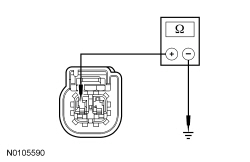 - Is the resistance greater than 10,000 ohms?
| Yes
GO to
N9
.
No
REPAIR circuit VR215 (YE/VT).
Refer to Wiring Diagrams Cell
5
, Connector Repair Procedures for schematic and connector information.
GO to
N11
.
|
|
N4 CHECK THE DRIVER SEAT TRACK POSITION SENSOR CIRCUIT FOR A SHORT TO VOLTAGE
|
|
| Yes
REPAIR circuit VR215 (YE/VT).
Refer to Wiring Diagrams Cell
5
, Connector Repair Procedures for schematic and connector information.
GO to
N11
.
No
GO to
N9
.
|
|
N5 CHECK THE DRIVER SEAT TRACK POSITION RESTRAINTS SENSOR DTC FOR A FAULT STATUS CHANGE (OPEN INDICATED)
|
|
NOTE:
This pinpoint test step will attempt to change the fault reported by the
by inducing a different fault condition. If the fault reported changes, this indicates the
is functioning correctly and is not the source of the fault.
- Ignition OFF.
- Depower the
. Refer to
Supplemental Restraint System (SRS) Depowering and Repowering
in this section.
- Disconnect: Drive Seat Side Air Bag Module C367 .
- Disconnect: Driver Seat Track Position Sensor C356 .
- Connect a fused jumper wire between driver seat track position sensor C356-2, circuit VR215 (YE/VT), harness side and C356-1, circuit GD138 (BK/WH), harness side.
- Repower the
.
Do not
prove out the system at this time. Refer to
Supplemental Restraint System (SRS) Depowering and Repowering
in this section.
- Ignition ON.
- Enter the following diagnostic mode on the scan tool: Self Test —
.
- DIAGNOSTIC TIP:
When viewing DTCs with the driver seat track position sensor circuits shorted together, a short to ground fault would normally be retrieved.
- Did the on-demand DTC change from B00B5:13 to B00B5:11?
| Yes
GO to
N8
.
No
GO to
N6
.
|
|
N6 CHECK THE DRIVER SEAT TRACK POSITION SENSOR CIRCUIT FOR AN OPEN
|
|
- Ignition OFF.
- Depower the
. Refer to
Supplemental Restraint System (SRS) Depowering and Repowering
in this section.
- Disconnect:
C2041A and C2041B .
- Remove the fused jumper wire from driver seat track position sensor C356.
- Measure the resistance between
C2041B-32, circuit VR215 (YE/VT), harness side and driver seat track position sensor C356-2, circuit VR215 (YE/VT), harness side.
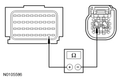 - Is the resistance less than 0.5 ohm?
| Yes
GO to
N7
.
No
REPAIR circuit VR215 (YE/VT).
Refer to Wiring Diagrams Cell
5
, Connector Repair Procedures for schematic and connector information.
GO to
N11
.
|
|
N7 CHECK THE DRIVER SEAT TRACK POSITION SENSOR GROUND CIRCUIT FOR AN OPEN
|
|
- Measure the resistance between driver seat track position sensor C356-1, circuit GD138 (BK/WH), harness side, and ground.
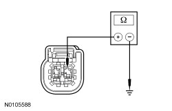 - Is the resistance less than 5 ohm?
| Yes
GO to
N9
.
No
REPAIR circuit GD138 (BK/WH).
Refer to Wiring Diagrams Cell
5
, Connector Repair Procedures for schematic and connector information.
GO to
N11
.
|
|
N8 CONFIRM THE DRIVER SEAT TRACK POSITION SENSOR FAULT
|
|
NOTE:
Make sure all restraint system components and the
electrical connectors are connected before carrying out the self-test. If not, DTCs will be recorded.
- Ignition OFF.
- Depower the
. Refer to
Supplemental Restraint System (SRS) Depowering and Repowering
in this section.
- If previously installed, remove the fused jumper wire from driver seat track position sensor C356.
- Prior to reconnecting any previously disconnected
component:
- inspect connector(s) (including any in-line connectors) for pushed-out, loose or spread terminals and loose or frayed wire connections at terminals.
- inspect wire harness for any damage, pinched, cut or pierced wires.
- Connect: All Previously Disconnected Component(s)/Connector(s) .
- Repower the
.
Do not
prove out the
at this time. Refer to
Supplemental Restraint System (SRS) Depowering and Repowering
in this section.
- Ignition ON.
- Enter the following diagnostic mode on the scan tool: Self Test —
.
- Was the original DTC retrieved on-demand during self-test?
| Yes
INSTALL a new driver seat track position sensor. REFER to
Seat Position Sensor
in this section. GO to
N11
.
No
In the process of diagnosing the fault, the fault condition has become intermittent.
Do not install any new
components at this time.
components should only be installed when directed to do so in the pinpoint test.
GO to
N10
.
|
|
N9 CONFIRM THE
FAULT
|
|
NOTE:
Make sure all restraint system components and the
electrical connectors are connected before carrying out the self-test. If not, DTCs will be recorded.
- Ignition OFF.
- Depower the
. Refer to
Supplemental Restraint System (SRS) Depowering and Repowering
in this section.
- Prior to reconnecting any previously disconnected
component:
- inspect connector(s) (including any in-line connectors) for pushed-out, loose or spread terminals and loose or frayed wire connections at terminals.
- inspect wire harness for any damage, pinched, cut or pierced wires.
- Connect: All Previously Disconnected Component(s)/Connector(s) .
- Repower the
.
Do not
prove out the
at this time. Refer to
Supplemental Restraint System (SRS) Depowering and Repowering
in this section.
- Ignition ON.
- Enter the following diagnostic mode on the scan tool: Self Test —
.
- Was the original DTC retrieved on-demand during self-test?
| Yes
INSTALL a new
. REFER to
Restraints Control Module (RCM)
in this section. GO to
N11
.
No
In the process of diagnosing the fault, the fault condition has become intermittent.
Do not install any new
components at this time.
components should only be installed when directed to do so in the pinpoint test.
GO to
N10
.
|
|
N10 CHECK FOR AN INTERMITTENT FAULT
|
|
| Yes
This fault cannot be cleared until it is corrected and the DTC is no longer retrieved on-demand during self-test.
For DTC B00B5:11 or B00B5:1D, GO to
N2
.
For DTC B00B5:12, GO to
N4
.
For DTC B00B5:13, GO to
N5
.
No
The fault is not present and cannot be recreated at this time.
Do not install any new
components at this time.
components should only be installed when directed to do so in the pinpoint test.
GO to
N11
.
|
|
N11 CHECK FOR ADDITIONAL
DTCs
|
|
- Ignition OFF.
- WARNING: Turn the ignition OFF and wait one minute to deplete the backup power supply. Failure to follow this instruction may result in serious personal injury or death in the event of an accidental deployment.
- Reconnect all
components (if previously disconnected).
- If previously directed to depower the
, repower the
.
Do not
prove out the
at this time. Refer to
Supplemental Restraint System (SRS) Depowering and Repowering
in this section.
- Ignition ON.
- Enter the following diagnostic mode on the scan tool: Self Test — Restraints .
- NOTE:
When selecting Restraints from the Self Test menu, DTCs will be retrieved from the
and
.
- Are any
and/or
DTCs retrieved on-demand during self-test?
| Yes
Do not clear any DTCs until all DTCs have been resolved. GO to the DTC Charts in this section for pinpoint test direction.
No
CLEAR all
and
. PROVE OUT the
. The repair is complete. RETURN the vehicle to the customer.
|
Pinpoint Test O: DTCs B00D5:11, B00D5:12 and B00D5:13
Refer to Wiring Diagrams Cell
46
, Supplemental Restraint System for schematic and connector information.
Normal Operation
The
briefly activates the Passenger Air Bag Deactivation (PAD) indicator to prove-out and verify to the occupants correct functional operation of the
indicator.
The
monitors the
indicator circuits for the following faults:
- Open circuit
- Short to voltage
- Short to ground
- Faulted
indicator
If a fault is detected, the
will store DTC B00D5:11, B00D5:12 or B00D5:13 in memory and send a message to the Instrument Panel Cluster (IPC) to illuminate the air bag warning indicator.
- DTC B00D5:11 (Restraint System Passenger Disable Indicator: Circuit Short to Ground) — When the
senses a short to ground on the
indicator circuit, a fault will be indicated.
- DTC B00D5:12 (Restraint System Passenger Disable Indicator: Circuit Short to Battery) — When the
senses a short to voltage on the
indicator circuit, a fault will be indicated.
- DTC B00D5:13 (Restraint System Passenger Disable Indicator: Circuit Open) — When the
senses an open circuit on the
indicator, a fault will be indicated. An open ignition circuit to the
indicator can set this DTC.
This pinpoint test is intended to diagnose the following:
- Wiring, terminals or connectors
- indicator
PINPOINT TEST O: DTCs B00D5:11, B00D5:12 AND B00D5:13
WARNING: Never probe the electrical connectors on airbag, Safety Canopy or side air curtain assemblies. Failure to follow this instruction may result in the accidental deployment of these assemblies, which increases the risk of serious personal injury or death.
NOTICE:
Use the correct probe adapter(s) from the Flex Probe Kit when taking measurements. Failure to use the correct probe adapter(s) may damage the connector.
Most faults are due to connector and/or wiring concerns. Carry out a thorough inspection and verification before proceeding with the pinpoint test.
NOTE:
Supplemental Restraint System (SRS) components should only be disconnected or reconnected when instructed to do so within a pinpoint test step. Failure to follow this instruction may result in incorrect diagnosis of the
.
NOTE:
Always make sure the correct
component is being installed. Parts released for other vehicles may not be compatible even if they appear physically similar. Check the part number listed in the Ford Catalog Advantage™ or equivalent to make sure the correct component is being installed. If an incorrect
component is installed, DTCs may set.
NOTE:
The
must be fully operational and free of faults before releasing the vehicle to the customer.
| Test Step
| Result / Action to Take
|
|---|
|
O1 RETRIEVE
DTCs
|
|
- Enter the following diagnostic mode on the scan tool: Self Test —
.
- Was DTC B00D5:11, B00D5:12 or B00D5:13 retrieved on-demand during self-test?
| Yes
This fault cannot be cleared until it is corrected and the DTC is no longer retrieved on-demand during self-test.
For DTC B00D5:11, GO to
O2
.
For DTC B00D5:13, GO to
O4
.
For DTC B00D5:12, GO to
O7
.
No
This is an intermittent fault when present as a Continuous Memory Diagnostic Trouble Code (CMDTC) only. GO to
O10
.
|
|
O2 CHECK THE
INDICATOR CIRCUIT FOR A SHORT TO GROUND
|
|
- Ignition OFF.
- WARNING: Turn the ignition OFF and wait one minute to deplete the backup power supply. Failure to follow this instruction may result in serious personal injury or death in the event of an accidental deployment.
- Disconnect:
Indicator C930 (hard top) or C9013 (convertible) .
- For hard tops, measure the resistance between
indicator C930-7, circuit CR116 (GN/WH), harness side and ground.
 - For convertibles, measure the resistance between
indicator C9013-10, circuit CR116 (GN/WH), harness side and ground.
 - Is the resistance greater than 10,000 ohms?
| Yes
GO to
O9
.
No
GO to
O3
.
|
|
O3 CHECK THE
FOR LOW RESISTANCE
|
|
| Yes
REPAIR circuit CR116 (GN/WH).
Refer to Wiring Diagrams Cell
5
, Connector Repair Procedures for schematic and connector information.
GO to
O11
.
No
GO to
O9
.
|
|
O4 CHECK THE IGNITION CIRCUIT AT
INDICATOR FOR VOLTAGE
|
|
- Ignition OFF.
- WARNING: Turn the ignition OFF and wait one minute to deplete the backup power supply. Failure to follow this instruction may result in serious personal injury or death in the event of an accidental deployment.
- Disconnect: PAD Indicator C930 (Hard Top) or C9013 (Convertible) .
- For hard tops, measure the voltage between
indicator C930-6, circuit CBP46 (WH/BU), harness side and ground.
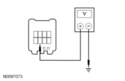 - For convertibles, measure the voltage between
indicator C9013-9, circuit CBP46 (WH/BU), harness side and ground.
 - Is the voltage greater than 10 volts?
| Yes
GO to
O5
.
No
VERIFY Smart Junction Box (SJB) fuse 46 (7.5A) is OK. If OK, REPAIR circuit CBP46 (WH/BU).
Refer to Wiring Diagrams Cell
5
, Connector Repair Procedures for schematic and connector information.
If not OK, REFER to the Wiring Diagrams manual to identify the possible causes of the circuit short. GO to
O11
.
|
|
O5 CHECK THE
INDICATOR CIRCUIT FOR AN OPEN
|
|
- Depower the
. Refer to
Supplemental Restraint System (SRS) Depowering and Repowering
in this section.
- Disconnect:
C2041A and C2041B .
- For convertibles, measure the resistance between
indicator C9013-10, circuit CR116 (GN/WH), harness side and
C2041A-22, circuit CR116 (GN/WH), harness side.
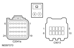 - For hard tops, measure the resistance between
indicator C930-7, circuit CR116 (GN/WH), harness side and C2041A-22, circuit CR116 (GN/WH), harness side.
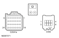 - Is the resistance less than 0.5 ohm?
| Yes
GO to
O6
.
No
REPAIR circuit CR116 (GN/WH).
Refer to Wiring Diagrams Cell
5
, Connector Repair Procedures for schematic and connector information.
GO to
O11
.
|
|
O6 CHECK THE
INDICATOR
|
|
- Connect:
Indicator C930 (hard top) or C9013 (convertible).
- Connect a fused jumper wire between
C2041A-22, circuit CR116 (GN/WH), harness side and ground.
 - Repower the
.
Do not
prove out the
at this time. Refer to
Supplemental Restraint System (SRS) Depowering and Repowering
in this section.
- Ignition ON.
- Does the
indicator illuminate?
| Yes
GO to
O9
.
No
INSTALL a new
indicator. REFER to
Passenger Airbag Deactivation (PAD) Indicator
in this section. GO to
O11
.
|
|
O7 CHECK THE
INDICATOR CIRCUIT FOR A SHORT TO VOLTAGE
|
|
| Yes
REPAIR circuit CR116 (GN/WH).
Refer to Wiring Diagrams Cell
5
, Connector Repair Procedures for schematic and connector information.
GO to
O11
.
No
GO to
O8
.
|
|
O8 CHECK THE
|
|
NOTE:
This pinpoint test step will attempt to change the fault reported by the
by inducing a different fault condition. If the fault reported changes, this indicates the
is functioning correctly and is not the source of the fault.
- Ignition OFF.
- Depower the
. Refer to
Supplemental Restraint System (SRS) Depowering and Repowering
in this section.
- Connect:
C2041A and C2041B .
- Repower the
.
Do not
prove out the
at this time. Refer to
Supplemental Restraint System (SRS) Depowering and Repowering
in this section.
- Ignition ON.
- Enter the following diagnostic mode on the scan tool: Self Test —
.
- DIAGNOSTIC TIP:
When viewing DTCs with the
indicator disconnected, an open circuit fault would normally be retrieved.
- Did the on-demand DTC change from B00D5:12 to B00D5:13?
| Yes
INSTALL a new
indicator. REFER to
Passenger Airbag Deactivation (PAD) Indicator
in this section.
No
GO to
O9
.
|
|
O9 CONFIRM THE
FAULT
|
|
NOTE:
Make sure all restraint system components and the
electrical connectors are connected before carrying out the self-test. If not, DTCs will be recorded.
- Ignition OFF.
- Depower the
. Refer to
Supplemental Restraint System (SRS) Depowering and Repowering
in this section.
- Prior to reconnecting any previously disconnected
component:
- inspect connector(s) (including any in-line connectors) for pushed-out, loose or spread terminals and loose or frayed wire connections at terminals.
- inspect wire harness for any damage, pinched, cut or pierced wires.
- Connect:
Indicator C930 (hard top) or C9013 (convertible) (if previously disconnected) .
- Connect:
C2041A and C2041B (if previously disconnected) .
- Repower the
.
Do not
prove out the
at this time. Refer to
Supplemental Restraint System (SRS) Depowering and Repowering
in this section.
- Enter the following diagnostic mode on the scan tool: Self Test —
.
- Was the original DTC retrieved on-demand during self-test?
| Yes
INSTALL a new
. REFER to
Restraints Control Module (RCM)
in this section. GO to
O11
.
No
In the process of diagnosing the fault, the fault condition has become intermittent.
Do not install any new
components at this time.
components should only be installed when directed to do so in the pinpoint test.
GO to
O10
.
|
|
O10 CHECK FOR AN INTERMITTENT FAULT
|
|
WARNING: Turn the ignition OFF and wait one minute to deplete the backup power supply. Failure to follow this instruction may result in serious personal injury or death in the event of an accidental deployment.
- Ignition OFF.
- Disconnect the
Indicator C930 (hard top) or C9013 (convertible) (if previously disconnected):
- Disconnect:
Indicator C930 (hard top) or C9013 (convertible) .
- Ignition ON.
- Enter the following diagnostic mode on the scan tool: Self Test —
.
- Was DTC B00D5:11, B00D5:12 or B00D5:13 retrieved on-demand during self-test?
| Yes
This fault cannot be cleared until it is corrected and the DTC is no longer retrieved on-demand during self-test.
For DTC B00D5:11, GO to
O2
.
For DTC B00D5:13, GO to
O4
.
For DTC B00D5:12, GO to
O7
.
No
CHECK for causes of intermittent open, short to ground or short to voltage on circuit CR116 (GN/WH). ATTEMPT to recreate the hard fault by flexing the wire harness and cycling the ignition frequently. ACTIVATE other systems in the same wire harness. REPAIR as necessary.
Refer to Wiring Diagrams Cell
5
, Connector Repair Procedures for schematic and connector information.
Do not install any new
components at this time.
components should only be installed when directed to do so in the pinpoint test.
GO to
O11
.
|
|
O11 CHECK FOR ADDITIONAL
DTCs
|
|
- Ignition OFF.
- WARNING: Turn the ignition OFF and wait one minute to deplete the backup power supply. Failure to follow this instruction may result in serious personal injury or death in the event of an accidental deployment.
- Reconnect all
components (if previously disconnected).
- If previously directed to depower the
, repower the
.
Do not
prove out the
at this time. Refer to
Supplemental Restraint System (SRS) Depowering and Repowering
in this section.
- Ignition ON.
- Enter the following diagnostic mode on the scan tool: Self Test — Restraints .
- NOTE:
When selecting Restraints from the Self Test menu, DTCs will be retrieved from the
and
.
- Are any
and/or
DTCs retrieved on-demand during self test?
| Yes
Do not clear any DTCs until all DTCs have been resolved. GO to the DTC Charts in this section for pinpoint test direction.
No
CLEAR all
and
. PROVE OUT the
. The repair is complete. RETURN the vehicle to the customer.
|
Pinpoint Test P: DTCs B1211:11, B1211:12, B1211:13 and B1211:1A
Refer to Wiring Diagrams Cell
46
, Supplemental Restraint System for schematic and connector information.
Normal Operation
The Restraints Control Module (RCM) continuously monitors driver safety belt retractor pretensioner and circuits for the following faults:
- Resistance out of range
- Unexpected voltage
- Short to ground
- Faulted driver safety belt retractor pretensioner
If a fault is detected, the
will set and store DTC B1211:11, B1211:12, B1211:13 or B1211:1A in memory and send a message to the Instrument Panel Cluster (IPC) to illuminate the air bag warning indicator.
The
analyzes the deployment loop resistance to determine if a fault exists. The value displayed in the PID is the deployment loop resistance as measured by the
. If the value displayed is lower or higher than the desired range (refer to diagram below), the
can set a DTC. As the deployment loop resistance drifts farther outside the desired range, the chance for a DTC increases. Small variations in resistance can occur due to the effect of road vibrations on terminal fit. Crimps and terminals can be affected by stress and harness movement and can cause an increase in resistance due to wire strain. These variables can result in an intermittent fault. For this reason, the test requires the PID value to be within the desired range before the fault is considered repaired, regardless if the module is reporting an on-demand DTC at time of diagnosis. Following this direction will help make sure that minor changes in resistance do not create a repeat concern. This test uses a process of elimination to diagnose each part of the deployment loop circuit including:
- Wiring
- Connections
- Driver safety belt retractor pretensioner
| DTC Description
| Fault Trigger Condition
|
|---|
- B1211:11 — Driver Seatbelt Retractor Pretensioner Deployment Control: Circuit Short to Ground
| When the
senses a short to ground on either driver safety belt retractor pretensioner circuit, a fault will be indicated.
|
- B1211:12 — Driver Seatbelt Retractor Pretensioner Deployment Control: Short to Battery
| When the
senses a short to battery on either driver safety belt retractor pretensioner circuit, a fault will be indicated.
|
- B1211:13 — Driver Seatbelt Retractor Pretensioner Deployment Control: Circuit Open
| When the
measures greater than the desired resistance range between the driver safety belt retractor pretensioner circuits, a fault will be indicated.
|
- B1211:1A — Driver Seatbelt Retractor Pretensioner Deployment Control: Circuit Resistance Below Threshold
| When the
measures less than the desired resistance range between the driver safety belt retractor pretensioner circuits, a fault will be indicated.
|
This pinpoint test is intended to diagnose the following:
- Wiring, terminals or connectors
- Driver safety belt retractor pretensioner
PINPOINT TEST P: DTCs B1211:11, B1211:12, B1211:13 AND B1211:1A
WARNING: Never disassemble or tamper with seat belt deployable components, including pretensioners, load limiters and inflators. Never back probe deployable device electrical connectors. Tampering or back probing may cause an accidental deployment and result in personal injury or death.
NOTICE:
Use the correct probe adapter(s) from the Flex Probe Kit when taking measurements. Failure to use the correct probe adapter(s) may damage the connector.
Most faults are due to connector and/or wiring concerns. Carry out a thorough inspection and verification before proceeding with the pinpoint test.
NOTE:
Supplemental Restraint System (SRS) components should only be disconnected or reconnected when instructed to do so within a pinpoint test step. Failure to follow this instruction may result in incorrect diagnosis of the
.
NOTE:
Always make sure the correct
component is being installed. Parts released for other vehicles may not be compatible even if they appear physically similar. Check the part number listed in the Ford Catalog Advantage™ or equivalent to make sure the correct component is being installed. If an incorrect
component is installed, DTCs may set.
NOTE:
The
must be fully operational and free of faults before releasing the vehicle to the customer.
| Test Step
| Result / Action to Take
|
|---|
|
P1 RETRIEVE THE
DTCs
|
|
- Ignition ON.
- Enter the following diagnostic mode on the scan tool: Self Test —
.
- Was DTC B1211:11, B1211:12, B1211:13 or B1211:1A retrieved on-demand during self-test?
| Yes
This fault cannot be cleared until it is corrected and the DTC is no longer retrieved on-demand during self-test.
For DTC B1211:13 or B1211:1A, GO to
P2
.
For DTC B1211:11, GO to
P9
.
For DTC B1211:12, GO to
P11
.
No
This is an intermittent fault when present as a Continuous Memory Diagnostic Trouble Code (CMDTC) only.
For DTC B1211:13 or B1211:1A, GO to
P14
.
For DTC B1211:11, GO to
P15
.
For DTC B1211:12, GO to
P16
.
|
|
P2 CHECK THE DRIVER SAFETY BELT RETRACTOR PRETENSIONER ELECTRICAL CONNECTOR
|
|
- Ignition OFF.
- Depower the
. Refer to
Supplemental Restraint System (SRS) Depowering and Repowering
in this section.
- Gain access to safety belt retractor pretensioner and inspect for the following:
- the Connector Position Assurance (CPA) tabs are not broken or the clip not damaged.
- the
clip is fully and correctly seated.
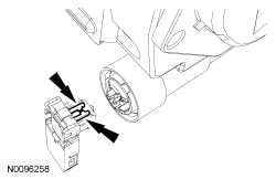 - Is the
clip installed correctly, not damaged or broken and fully seated?
| Yes
GO to
P3
.
No
If the
clip is damaged or broken, INSTALL a pigtail connector for the pretensioner using pigtail kit (8U2Z-14S411-YA).
If the
clip is not correctly installed or seated, REPAIR as necessary.
Refer to Wiring Diagrams Cell
5
, Connector Repair Procedures for schematic and connector information.
GO to
P18
.
|
|
P3 CHECK THE DRIVER SEATBELT RETRACTOR PRETENSIONER DEPLOYMENT CONTROL RESISTANCE (DEPLOY_23_R) PID
|
|
- Repower the
.
Do not
prove out the
at this time. Refer to
Supplemental Restraint System (SRS) Depowering and Repowering
in this section.
- Ignition ON.
- Enter the following diagnostic mode on the scan tool: DataLogger —
.
- Monitor and record the resistance value displayed by the DEPLOY_23_R PID.
- Does the recorded PID value read between 1.7 and 2.78 ohms?
| Yes
GO to
P13
.
No
GO to
P4
.
|
|
P4 CHECK THE DRIVER SEATBELT RETRACTOR PRETENSIONER DEPLOYMENT CONTROL RESISTANCE (DEPLOY_23_R) PID WHILE CARRYING OUT THE HARNESS TEST
|
|
- While monitoring the DEPLOY_23_R PID carry out the harness test of the driver safety belt retractor pretensioner circuits and accessible connectors (including any in-line connectors) by wiggling connectors and flexing the wire harness frequently.
- Does the PID value read between 1.7 and 2.78 ohms while carrying out a harness test?
| Yes
DEPOWER the
and REPAIR the connector, terminals or wire harness as needed.
Refer to Wiring Diagrams Cell
5
, Connector Repair Procedures for schematic and connector information.
GO to
P18
.
No
For PID value less than 1.7 ohms, GO to
P5
.
For PID value greater than 2.78 ohms, GO to
P7
.
|
|
P5 CHECK THE DRIVER SEATBELT RETRACTOR PRETENSIONER DEPLOYMENT CONTROL DTC FOR A FAULT STATUS CHANGE (LOW RESISTANCE INDICATED)
|
|
NOTE:
This pinpoint test step will attempt to change the fault reported by the
by inducing a different fault condition. If the fault reported changes, this indicates the
is functioning correctly and is not the source of the fault.
- Ignition OFF.
- Depower the
. Refer to
Supplemental Restraint System (SRS) Depowering and Repowering
in this section.
- Disconnect: Driver Safety Belt Retractor Pretensioner C3338 .
- Repower the
.
Do not
prove out the
at this time. Refer to
Supplemental Restraint System (SRS) Depowering and Repowering
in this section.
- Ignition ON.
- Enter the following diagnostic mode on the scan tool: Self Test —
.
- DIAGNOSTIC TIP:
When viewing DTCs with the driver safety belt retractor pretensioner disconnected, an open circuit fault would normally be retrieved.
- Did the on-demand DTC change from B1211:1A to B1211:13?
| Yes
GO to
P12
.
No
GO to
P6
.
|
|
P6 CHECK FOR A SHORT BETWEEN DRIVER SAFETY BELT RETRACTOR PRETENSIONER CIRCUITS
|
|
- Ignition OFF.
- Depower the
. Refer to
Supplemental Restraint System (SRS) Depowering and Repowering
in this section.
- Disconnect:
C2041A and C2041B .
- Measure the resistance between the driver safety belt retractor pretensioner C3338-2, circuit CR120 (BU/OG), harness side and C3338-1, circuit RR120 (BN/GN), harness side.
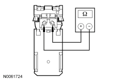 - Is the resistance greater than 10,000 ohms?
| Yes
GO to
P13
.
No
REPAIR circuits CR120 (BU/OG) and RR120 (BN/GN).
Refer to Wiring Diagrams Cell
5
, Connector Repair Procedures for schematic and connector information.
GO to
P18
.
|
|
P7 CHECK THE DRIVER SAFETY BELT RETRACTOR PRETENSIONER CIRCUITS FOR AN OPEN
|
|
- Ignition OFF.
- Depower the
. Refer to
Supplemental Restraint System (SRS) Depowering and Repowering
in this section.
- Disconnect: Drive Safety Belt Retractor Pretensioner C3338 .
- Disconnect:
C2041A and C2041B .
- Measure the resistance between
C2041B, harness side and driver safety belt retractor pretensioner C3338, harness side using the following chart:
| Circuit
| Driver Safety Belt Retractor Pretensioner
|
|---|
| C2041B-3
| CR120 (BU/OG)
| C3338-2
| | C2041B-4
| RR120 (BN/GN)
| C3338-1
|
 - Are the resistances less than 0.5 ohm?
| Yes
GO to
P8
.
No
REPAIR circuit CR120 (BU/OG) or RR120 (BN/GN).
Refer to Wiring Diagrams Cell
5
, Connector Repair Procedures for schematic and connector information.
GO to
P18
.
|
|
P8 CHECK THE DRIVER SEATBELT RETRACTOR PRETENSIONER DEPLOYMENT CONTROL DTC FOR A FAULT STATUS CHANGE (OPEN INDICATED)
|
|
NOTE:
This pinpoint test step will attempt to change the fault reported by the
by inducing a different fault condition. If the fault reported changes, this indicates the
is functioning correctly and is not the source of the fault.
- Connect:
C2041A and C2041B .
- Connect a fused jumper wire between the driver safety belt retractor pretensioner C3338-2, circuit CR120 (BU/OG), harness side and C3338-1, circuit RR120 (BN/GN), harness side.
- Repower the
.
Do not
prove out the
at this time. Refer to
Supplemental Restraint System (SRS) Depowering and Repowering
in this section.
- Ignition ON.
- Enter the following diagnostic mode on the scan tool: Self Test —
.
- DIAGNOSTIC TIP:
When viewing DTCs with the driver safety belt retractor pretensioner circuits shorted together, a low resistance fault would normally be retrieved.
- Did the on-demand DTC change from B1211:13 to B1211:1A?
| Yes
GO to
P12
.
No
GO to
P13
.
|
|
P9 CHECK THE DRIVER SEATBELT RETRACTOR PRETENSIONER DEPLOYMENT CONTROL DTC FOR A FAULT STATUS CHANGE (SHORT TO GROUND INDICATED)
|
|
NOTE:
This pinpoint test step will attempt to change the fault reported by the
by inducing a different fault condition. If the fault reported changes, this indicates the
is functioning correctly and is not the source of the fault.
- Ignition OFF.
- Depower the
. Refer to
Supplemental Restraint System (SRS) Depowering and Repowering
in this section.
- Disconnect: Driver Safety Belt Retractor Pretensioner C3338 .
- Repower the
.
Do not
prove out the
at this time. Refer to
Supplemental Restraint System (SRS) Depowering and Repowering
in this section.
- Ignition ON.
- Enter the following diagnostic mode on the scan tool: Self Test —
.
- DIAGNOSTIC TIP:
When viewing DTCs with the driver safety belt retractor pretensioner disconnected, an open circuit fault would normally be retrieved.
- Did the on-demand DTC change from B1211:11 to B1211:13?
| Yes
GO to
P12
.
No
GO to
P10
.
|
|
P10 CHECK THE DRIVER SAFETY BELT RETRACTOR PRETENSIONER CIRCUITS FOR A SHORT TO GROUND
|
|
- Ignition OFF.
- Depower the
. Refer to
Supplemental Restraint System (SRS) Depowering and Repowering
in this section.
- Disconnect:
C2041A and C2041B .
- Measure the resistance between the driver safety belt retractor pretensioner:
- C3338-2, circuit CR120 (BU/OG), harness side and ground.
- C3338-1, circuit RR120 (BN/GN), harness side and ground.
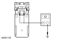 - Are the resistances greater than 10,000 ohms?
| Yes
GO to
P13
.
No
REPAIR circuit CR120 (BU/OG) or RR120 (BN/GN).
Refer to Wiring Diagrams Cell
5
, Connector Repair Procedures for schematic and connector information.
GO to
P18
.
|
|
P11 CHECK THE DRIVER SAFETY BELT RETRACTOR PRETENSIONER CIRCUITS FOR A SHORT TO VOLTAGE
|
|
| Yes
REPAIR circuit CR120 (BU/OG) or RR120 (BN/GN).
Refer to Wiring Diagrams Cell
5
, Connector Repair Procedures for schematic and connector information.
GO to
P18
.
No
GO to
P13
.
|
|
P12 CONFIRM THE DRIVER SAFETY BELT RETRACTOR PRETENSIONER FAULT
|
|
NOTE:
Make sure all restraint system components and the
electrical connectors are connected before carrying out the self-test. If not, DTCs will be recorded.
- Ignition OFF.
- Depower the
. Refer to
Supplemental Restraint System (SRS) Depowering and Repowering
in this section.
- If previously installed, remove the fused jumper wire from driver safety belt retractor pretensioner C3338.
- Prior to reconnecting any previously disconnected
component:
- inspect connector(s) (including any in-line connectors) for pushed out, loose or spread terminals and loose or frayed wire connections at terminals.
- inspect wire harness for any damage, pinched, cut or pierced wires.
- Connect: Driver Safety Belt Retractor Pretensioner C3338 .
- Connect:
C2041A and C2041B (if previously disconnected) .
- Repower the
.
Do not
prove out the
at this time. Refer to
Supplemental Restraint System (SRS) Depowering and Repowering
in this section.
- Ignition ON.
- Enter the following diagnostic mode on the scan tool: Self Test —
.
- Was the original DTC retrieved on-demand during self-test?
| Yes
INSTALL a new driver safety belt retractor pretensioner. REFER to
Section 501-20A
. GO to
P18
.
No
In the process of diagnosing the fault, the fault condition has become intermittent.
Do not install any new
components at this time.
components should only be installed when directed to do so in the pinpoint test.
For DTC B1211:13 or B1211:1A, GO to
P14
.
For DTC B1211:11, GO to
P15
.
For DTC B1211:12, GO to
P16
.
|
|
P13 CONFIRM THE
FAULT
|
|
NOTE:
Make sure all restraint system components, sensor electrical connectors and the
electrical connectors are connected before carrying out the self-test. If not, DTCs will be recorded.
- Ignition OFF.
- Depower the
. Refer to
Supplemental Restraint System (SRS) Depowering and Repowering
in this section.
- If previously installed, remove the fused jumper wire from driver safety belt pretensioner retractor C3338.
- Prior to reconnecting any previously disconnected
component:
- inspect connector(s) (including any in-line connectors) for pushed out, loose or spread terminals and loose or frayed wire connections at terminals.
- inspect wire harness for any damage, pinched, cut or pierced wires.
- Connect: Driver Safety Belt Retractor Pretensioner C3338 .
- Connect:
C2041A and C2041B (if previously disconnected) .
- Repower the
.
Do not
prove out the
at this time. Refer to
Supplemental Restraint System (SRS) Depowering and Repowering
in this section.
- Ignition ON.
- Enter the following diagnostic mode on the scan tool: Self Test —
.
- Was the original DTC retrieved on-demand during self-test?
| Yes
INSTALL a new
. REFER to
Restraints Control Module (RCM)
in this section. GO to
P18
.
No
In the process of diagnosing the fault, the fault condition has become intermittent.
Do not install any new
components at this time.
components should only be installed when directed to do so in the pinpoint test.
For DTC B1211:13 or B1211:1A, GO to
P14
.
For DTC B1211:11, GO to
P15
.
For DTC B1211:12, GO to
P16
.
|
|
P14 CHECK THE DRIVER SEATBELT RETRACTOR PRETENSIONER DEPLOYMENT CONTROL RESISTANCE (DEPLOY_23_R) PID FOR AN INTERMITTENT LOW RESISTANCE OR OPEN CIRCUIT FAULT
|
|
- Enter the following diagnostic mode on the scan tool: DataLogger —
.
- Attempt to recreate the fault by wiggling the connectors (including any in-line connectors) and flexing the wire harness frequently.
- Does the PID value read between 1.7 and 2.78 ohms?
| Yes
The fault is not present and cannot be recreated at this time.
Do not install any new
components at this time.
components should only be installed when directed to do so in the pinpoint test.
GO to
P17
.
No
DEPOWER the
and REPAIR as necessary.
Refer to Wiring Diagrams Cell
5
, Connector Repair Procedures for schematic and connector information.
GO to
P18
.
|
|
P15 CHECK THE DRIVER SEATBELT RETRACTOR PRETENSIONER DEPLOYMENT CONTROL FOR AN INTERMITTENT SHORT TO GROUND FAULT
|
|
- Ignition ON.
- Attempt to recreate the fault by wiggling connectors (including any in-line connectors) and flexing the wire harness frequently.
- Enter the following diagnostic mode on the scan tool: Self Test —
.
- Was DTC B1211:11 retrieved on-demand during self-test?
| Yes
DEPOWER the
and REPAIR as necessary.
Refer to Wiring Diagrams Cell
5
, Connector Repair Procedures for schematic and connector information.
GO to
P18
.
No
The fault is not present and cannot be recreated at this time.
Do not install any new
components at this time.
components should only be installed when directed to do so in the pinpoint test.
GO to
P17
.
|
|
P16 CHECK THE DRIVER SEATBELT RETRACTOR PRETENSIONER DEPLOYMENT CONTROL FOR AN INTERMITTENT SHORT TO VOLTAGE FAULT
|
|
| Yes
DEPOWER the
and REPAIR as necessary.
Refer to Wiring Diagrams Cell
5
, Connector Repair Procedures for schematic and connector information.
GO to
P18
.
No
The fault is not present and cannot be recreated at this time.
Do not install any new
components at this time.
components should only be installed when directed to do so in the pinpoint test.
GO to
P17
.
|
|
P17 CHECK THE HARNESS AND CONNECTORS
|
|
- Ignition OFF.
- Depower the
. Refer to
Supplemental Restraint System (SRS) Depowering and Repowering
in this section.
- Disconnect the driver safety belt retractor pretensioner C3338:
- inspect connector(s) (including any in-line connectors) for corrosion, loose or spread terminals and loose or frayed wire connections at terminals.
- inspect wire harness for any damage, pinched, cut or pierced wires.
- Inspect
C2041A and C2041B
lever/lock for correct operation. Refer to
Restraints Control Module (RCM)
in this section.
- Were any concerns found?
| Yes
REPAIR as necessary.
Refer to Wiring Diagrams Cell
5
, Connector Repair Procedures for schematic and connector information.
GO to
P18
.
No
The fault is not present and cannot be recreated at this time.
Do not install any new
components at this time.
components should only be installed when directed to do so in the pinpoint test.
GO to
P18
.
|
|
P18 CHECK FOR ADDITIONAL
DTCs
|
|
- Ignition OFF.
- WARNING: Turn the ignition OFF and wait one minute to deplete the backup power supply. Failure to follow this instruction may result in serious personal injury or death in the event of an accidental deployment.
- Reconnect all
components (if previously disconnected).
- If previously directed to depower the
, repower the
.
Do not
prove out the
at this time. Refer to
Supplemental Restraint System (SRS) Depowering and Repowering
in this section.
- Ignition ON.
- Enter the following diagnostic mode on the scan tool: Self Test — Restraints .
- NOTE:
When selecting Restraints from the Self Test menu, DTCs will be retrieved from the
and Occupant Classification System Module (OCSM).
- Are any
and/or
DTCs retrieved on-demand during self-test?
| Yes
Do not clear any DTCs until all DTCs have been resolved. GO to the DTC Charts in this section for pinpoint test direction.
No
CLEAR all
and
. PROVE OUT the
. The repair is complete. RETURN the vehicle to the customer.
|
Pinpoint Test Q: DTCs B1214:11, B1214:12, B1214:13 and B1214:1A
Refer to Wiring Diagrams Cell
46
, Supplemental Restraint System for schematic and connector information.
Normal Operation
The Restraints Control Module (RCM) continuously monitors the passenger safety belt retractor pretensioner and circuits for the following faults:
- Resistance out of range
- Unexpected voltage
- Short to ground
- Faulted passenger safety belt buckle pretensioner
If a fault is detected, the
will store DTC B1214:11, B1214:12, B1214:13 or B1214:1A in memory and send a message to the Instrument Panel Cluster (IPC) to illuminate the air bag warning indicator.
The
analyzes the deployment loop resistance to determine if a fault exists. The value displayed in the PID is the deployment loop resistance as measured by the
. If the value displayed is lower or higher than the desired range (refer to diagram below), the
can set a DTC. As the deployment loop resistance drifts farther outside the desired range, the chance for a DTC increases. Small variations in resistance can occur due to the effect of road vibrations on terminal fit. Crimps and terminals can be affected by stress and harness movement and can cause an increase in resistance due to wire strain. These variables can result in an intermittent fault. For this reason, the test requires the PID value to be within the desired range before the fault is considered repaired, regardless if the module is reporting an on-demand DTC at time of diagnosis. Following this direction will help make sure that minor changes in resistance do not create a repeat concern. This test uses a process of elimination to diagnose each part of the deployment loop circuit including:
- Wiring
- Connections
- Passenger safety belt retractor pretensioner
| DTC Description
| Fault Trigger Condition
|
|---|
- B1214:11 — Passenger Seatbelt Retractor Pretensioner Deployment Control: Circuit Short to Ground
| When the
senses a short to ground on either passenger safety belt retractor pretensioner circuit, a fault will be indicated.
|
- B1214:12 — Passenger Seatbelt Retractor Pretensioner Deployment Control: Short to Battery
| When the
senses a short to battery on either passenger safety belt retractor pretensioner circuit, a fault will be indicated.
|
- B1214:13 — Passenger Seatbelt Retractor Pretensioner Deployment Control: Circuit Open
| When the
measures greater than the desired resistance range between the passenger safety belt retractor pretensioner circuits, a fault will be indicated.
|
- B1214:1A — Passenger Seatbelt Retractor Pretensioner Deployment Control: Circuit Resistance Below Threshold
| When the
measures less than the desired resistance range between the passenger safety belt retractor pretensioner circuits, a fault will be indicated.
|
This pinpoint test is intended to diagnose the following:
- Wiring, terminals or connectors
- Passenger safety belt retractor pretensioner
PINPOINT TEST Q: DTCs B1214:11, B1214:12, B1214:13 AND B1214:1A
WARNING: Never disassemble or tamper with seat belt deployable components, including pretensioners, load limiters and inflators. Never back probe deployable device electrical connectors. Tampering or back probing may cause an accidental deployment and result in personal injury or death.
NOTICE:
Use the correct probe adapter(s) from the Flex Probe Kit when taking measurements. Failure to use the correct probe adapter(s) may damage the connector.
Most faults are due to connector and/or wiring concerns. Carry out a thorough inspection and verification before proceeding with the pinpoint test.
NOTE:
Supplemental Restraint System (SRS) components should only be disconnected or reconnected when instructed to do so within a pinpoint test step. Failure to follow this instruction may result in incorrect diagnosis of the
.
NOTE:
Always make sure the correct
component is being installed. Parts released for other vehicles may not be compatible even if they appear physically similar. Check the part number listed in the Ford Catalog Advantage™ or equivalent to make sure the correct component is being installed. If an incorrect
component is installed, DTCs may set.
NOTE:
The
must be fully operational and free of faults before releasing the vehicle to the customer.
| Test Step
| Result / Action to Take
|
|---|
|
Q1 RETRIEVE THE
DTCs
|
|
- Ignition ON.
- Enter the following diagnostic mode on the scan tool: Self Test —
.
- Was DTC B1214:11, B1214:12, B1214:13 or B1214:1A retrieved on-demand during self-test?
| Yes
This fault cannot be cleared until it is corrected and the DTC is no longer retrieved on-demand during self-test.
For DTC B1214:13 or B1214:1A, GO to
Q2
.
For DTC B1214:11, GO to
Q9
.
For DTC B1214:12, GO to
Q11
.
No
This is an intermittent fault when present as a Continuous Memory Diagnostic Trouble Code (CMDTC) only.
For DTC B1214:13 or B1214:1A, GO to
Q14
.
For DTC B1214:11, GO to
Q15
.
For DTC B1214:12, GO to
Q16
.
|
|
Q2 CHECK THE PASSENGER SAFETY BELT RETRACTOR PRETENSIONER ELECTRICAL CONNECTOR
|
|
- Ignition OFF.
- Depower the
. Refer to
Supplemental Restraint System (SRS) Depowering and Repowering
in this section.
- Gain access to safety belt retractor pretensioner and inspect for the following:
- the Connector Position Assurance (CPA) tabs are not broken or the clip not damaged.
- the
clip is fully and correctly seated.
- Is the
clip installed correctly, not damaged or broken and fully seated?
| Yes
GO to
Q3
.
No
If the
clip is damaged or broken, INSTALL a pigtail connector for the pretensioner using pigtail kit (8U2Z-14S411-YA).
If the
clip is not correctly installed or seated, REPAIR as necessary.
Refer to Wiring Diagrams Cell
5
, Connector Repair Procedures for schematic and connector information.
GO to
Q18
.
|
|
Q3 CHECK THE PASSENGER SEATBELT RETRACTOR PRETENSIONER DEPLOYMENT CONTROL RESISTANCE (DEPLOY_24_R) PID
|
|
- Repower the
.
Do not
prove out the
at this time. Refer to
Supplemental Restraint System (SRS) Depowering and Repowering
in this section.
- Ignition ON.
- Enter the following diagnostic mode on the scan tool: DataLogger —
.
- Monitor and record the resistance value displayed by the DEPLOY_24_R PID.
- Does the recorded PID value read between 1.7 and 2.78 ohms?
| Yes
GO to
Q13
.
No
GO to
Q4
.
|
|
Q4 CHECK THE PASSENGER SEATBELT RETRACTOR PRETENSIONER DEPLOYMENT CONTROL RESISTANCE (DEPLOY_24_R) PID WHILE CARRYING OUT THE HARNESS TEST
|
|
- While monitoring the DEPLOY_24_R PID, carry out the harness test of the passenger safety belt retractor pretensioner circuits and accessible connectors (including any in-line connectors) by wiggling connectors and flexing the wire harness frequently.
- Does the PID value read between 1.7 and 2.78 ohms while carrying out a harness test?
| Yes
DEPOWER the
and REPAIR the connector, terminals or wire harness as needed.
Refer to Wiring Diagrams Cell
5
, Connector Repair Procedures for schematic and connector information.
GO to
Q18
.
No
For PID value less than 1.7 ohms, GO to
Q5
.
For PID value greater than 2.78 ohms, GO to
Q7
.
|
|
Q5 CHECK THE PASSENGER SEATBELT RETRACTOR PRETENSIONER DEPLOYMENT CONTROL DTC FOR A FAULT STATUS CHANGE (LOW RESISTANCE INDICATED)
|
|
NOTE:
This pinpoint test step will attempt to change the fault reported by the
by inducing a different fault condition. If the fault reported changes, this indicates the
is functioning correctly and is not the source of the fault.
- Ignition OFF.
- Depower the
. Refer to
Supplemental Restraint System (SRS) Depowering and Repowering
in this section.
- Disconnect: Passenger Safety Belt Retractor Pretensioner C3336 .
- Repower the
.
Do not
prove out the
at this time. Refer to
Supplemental Restraint System (SRS) Depowering and Repowering
in this section.
- Ignition ON.
- Enter the following diagnostic mode on the scan tool: Self Test —
.
- DIAGNOSTIC TIP:
When viewing DTCs with the passenger safety belt retractor pretensioner disconnected, an open circuit fault would normally be retrieved.
- Did the on-demand DTC change from B1214:1A to B1214:13?
| Yes
GO to
Q12
.
No
GO to
Q6
.
|
|
Q6 CHECK FOR A SHORT BETWEEN PASSENGER SAFETY BELT RETRACTOR PRETENSIONER CIRCUITS
|
|
- Ignition OFF.
- Depower the
. Refer to
Supplemental Restraint System (SRS) Depowering and Repowering
in this section.
- Disconnect:
C2041A and C2041B .
- Measure the resistance between the passenger safety belt retractor pretensioner C3336-2, circuit CR122 (WH/OG), harness side and C3336-1, circuit RR122 (BN), harness side.
- Is the resistance greater than 10,000 ohms?
| Yes
GO to
Q13
.
No
REPAIR circuits CR122 (WH/OG) and RR122 (BN).
Refer to Wiring Diagrams Cell
5
, Connector Repair Procedures for schematic and connector information.
GO to
Q18
.
|
|
Q7 CHECK THE PASSENGER SAFETY BELT RETRACTOR PRETENSIONER CIRCUITS FOR AN OPEN
|
|
- Ignition OFF.
- Depower the
. Refer to
Supplemental Restraint System (SRS) Depowering and Repowering
in this section.
- Disconnect: Passenger Safety Belt Retractor Pretensioner C3336 .
- Disconnect:
C2041A and C2041B .
- Measure the resistance between
C2041B, and passenger safety belt retractor pretensioner C3336, harness side using the following chart:
| Circuit
| Passenger Safety Belt Retractor Pretensioner
|
|---|
| C2041B-14
| RR122 (BN)
| C3336-1
| | C2041B-13
| CR122 (WH/OG)
| C3336-2
|
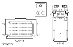 - Are the resistances less than 0.5 ohm?
| Yes
GO to
Q8
.
No
REPAIR circuit CR122 (WH/OG) or RR122 (BN).
Refer to Wiring Diagrams Cell
5
, Connector Repair Procedures for schematic and connector information.
GO to
Q18
.
|
|
Q8 CHECK THE PASSENGER SEATBELT RETRACTOR PRETENSIONER DEPLOYMENT CONTROL DTC FOR A FAULT STATUS CHANGE (OPEN INDICATED)
|
|
NOTE:
This pinpoint test step will attempt to change the fault reported by the
by inducing a different fault condition. If the fault reported changes, this indicates the
is functioning correctly and is not the source of the fault.
- Connect:
C2041A and C2041B .
- Connect a fused jumper wire between the passenger safety belt retractor pretensioner C3336-2, circuit CR122 (WH/OG), harness side and C3336-1, circuit RR122 (BN), harness side.
- Repower the
.
Do not
prove out the
at this time. Refer to
Supplemental Restraint System (SRS) Depowering and Repowering
in this section.
- Ignition ON.
- Enter the following diagnostic mode on the scan tool: Self Test —
.
- DIAGNOSTIC TIP:
When viewing DTCs with the passenger safety belt retractor pretensioner circuits shorted together, a low resistance fault would normally be retrieved.
- Did the on-demand DTC change from B1214:13 to B1214:1A?
| Yes
GO to
Q12
.
No
GO to
Q13
.
|
|
Q9 CHECK THE PASSENGER SEATBELT RETRACTOR PRETENSIONER DEPLOYMENT CONTROL DTC FOR A FAULT STATUS CHANGE (SHORT TO GROUND INDICATED)
|
|
NOTE:
This pinpoint test step will attempt to change the fault reported by the
by inducing a different fault condition. If the fault reported changes, this indicates the
is functioning correctly and is not the source of the fault.
- Ignition OFF.
- Depower the
. Refer to
Supplemental Restraint System (SRS) Depowering and Repowering
in this section.
- Disconnect: Passenger Safety Belt Retractor Pretensioner C3336 .
- Repower the
.
Do not
prove out the
at this time. Refer to
Supplemental Restraint System (SRS) Depowering and Repowering
in this section.
- Ignition ON.
- Enter the following diagnostic mode on the scan tool: Self Test —
.
- DIAGNOSTIC TIP:
When viewing DTCs with the passenger safety belt retractor pretensioner disconnected, an open circuit fault would normally be retrieved.
- Did the on-demand DTC change from B1214:11 to B1214:13?
| Yes
GO to
Q12
.
No
GO to
Q10
.
|
|
Q10 CHECK THE PASSENGER SAFETY BELT RETRACTOR PRETENSIONER CIRCUITS FOR A SHORT TO GROUND
|
|
- Ignition OFF.
- Depower the
. Refer to
Supplemental Restraint System (SRS) Depowering and Repowering
in this section.
- Disconnect:
C2041A and C2041B .
- Measure the resistance between the passenger safety belt retractor pretensioner:
- C3336-2, circuit CR122 (WH/OG), harness side and ground.
- C3336-1, circuit RR122 (BN), harness side and ground.
- Are the resistances greater than 10,000 ohms?
| Yes
GO to
Q13
.
No
REPAIR circuit CR122 (WH/OG) or RR122 (BN).
Refer to Wiring Diagrams Cell
5
, Connector Repair Procedures for schematic and connector information.
GO to
Q18
.
|
|
Q11 CHECK THE PASSENGER SAFETY BELT RETRACTOR PRETENSIONER CIRCUITS FOR A SHORT TO VOLTAGE
|
|
| Yes
REPAIR circuit CR122 (WH/OG) or RR122 (BN).
Refer to Wiring Diagrams Cell
5
, Connector Repair Procedures for schematic and connector information.
GO to
Q18
.
No
GO to
Q13
.
|
|
Q12 CONFIRM THE PASSENGER SAFETY BELT RETRACTOR PRETENSIONER FAULT
|
|
NOTE:
Make sure all restraint system components and the
electrical connectors are connected before carrying out the self-test. If not, DTCs will be recorded.
- Ignition OFF.
- Depower the
. Refer to
Supplemental Restraint System (SRS) Depowering and Repowering
in this section.
- If previously installed, remove the fused jumper wire from the passenger safety belt retractor pretensioner C3336.
- Prior to reconnecting any previously disconnected
component:
- inspect connector(s) (including any in-line connectors) for pushed out, loose or spread terminals and loose or frayed wire connections at terminals.
- inspect wire harness for any damage, pinched, cut or pierced wires.
- Depower the
. Refer to
Supplemental Restraint System (SRS) Depowering and Repowering
in this section.
- Connect: Passenger Safety Belt Retractor Pretensioner C3336 .
- Connect:
C2041A and C2041B (if previously disconnected) .
- Repower the
.
Do not
prove out the
at this time. Refer to
Supplemental Restraint System (SRS) Depowering and Repowering
in this section.
- Ignition ON.
- Enter the following diagnostic mode on the scan tool: Self Test —
.
- Was the original DTC retrieved on-demand during self-test?
| Yes
INSTALL a new passenger safety belt retractor pretensioner. REFER to
Section 501-20A
. GO to
Q18
.
No
In the process of diagnosing the fault, the fault condition has become intermittent.
Do not install any new
components at this time.
components should only be installed when directed to do so in the pinpoint test.
For DTC B1214:13 or B1214:1A, GO to
Q14
.
For DTC B1214:11, GO to
Q15
.
For DTC B1214:12, GO to
Q16
.
|
|
Q13 CONFIRM THE
FAULT
|
|
NOTE:
Make sure all restraint system components and the
electrical connectors are connected before carrying out the self-test. If not, DTCs will be recorded.
- Ignition OFF.
- Depower the
. Refer to
Supplemental Restraint System (SRS) Depowering and Repowering
in this section.
- If previously installed, remove the fused jumper wire from passenger safety belt retractor C3336.
- Prior to reconnecting any previously disconnected
component:
- inspect connector(s) (including any in-line connectors) for pushed out, loose or spread terminals and loose or frayed wire connections at terminals.
- inspect wire harness for any damage, pinched, cut or pierced wires.
- Connect: Passenger Safety Belt Retractor Pretensioner C3336 .
- Connect:
C2041A and C2041B (if previously disconnected) .
- Repower the
.
Do not
prove out the
at this time. Refer to
Supplemental Restraint System (SRS) Depowering and Repowering
in this section.
- Ignition ON.
- Enter the following diagnostic mode on the scan tool: Self Test —
.
- Was the original DTC retrieved on-demand during self-test?
| Yes
INSTALL a new
. REFER to
Restraints Control Module (RCM)
in this section. GO to
Q18
.
No
In the process of diagnosing the fault, the fault condition has become intermittent.
Do not install any new
components at this time.
components should only be installed when directed to do so in the pinpoint test.
For DTC B1214:13 or B1214:1A, GO to
Q14
.
For DTC B1214:11, GO to
Q15
.
For DTC B1214:12, GO to
Q16
.
|
|
Q14 CHECK THE PASSENGER SEATBELT RETRACTOR PRETENSIONER DEPLOYMENT CONTROL RESISTANCE DEPLOY_24_R PID FOR AN INTERMITTENT LOW RESISTANCE OR OPEN CIRCUIT FAULT
|
|
- Enter the following diagnostic mode on the scan tool: DataLogger —
.
- Attempt to recreate the fault by wiggling the connectors (including any in-line connectors) and flexing the wire harness frequently.
- Does the PID value read between 1.7 and 2.78 ohms?
| Yes
The fault is not present and cannot be recreated at this time.
Do not install any new
components at this time.
components should only be installed when directed to do so in the pinpoint test.
GO to
Q17
.
No
DEPOWER the
and REPAIR as necessary.
Refer to Wiring Diagrams Cell
5
, Connector Repair Procedures for schematic and connector information.
GO to
Q18
.
|
|
Q15 CHECK THE PASSENGER SEATBELT RETRACTOR PRETENSIONER DEPLOYMENT CONTROL FOR AN INTERMITTENT SHORT TO GROUND FAULT
|
|
- Ignition ON.
- Attempt to recreate the fault by wiggling connectors (including any in-line connectors) and flexing the wire harness frequently.
- Enter the following diagnostic mode on the scan tool: Self Test —
.
- Was DTC B1214:11 retrieved on-demand during self-test?
| Yes
DEPOWER the
and REPAIR as necessary.
Refer to Wiring Diagrams Cell
5
, Connector Repair Procedures for schematic and connector information.
GO to
Q18
.
No
The fault is not present and cannot be recreated at this time.
Do not install any new
components at this time.
components should only be installed when directed to do so in the pinpoint test.
GO to
Q17
.
|
|
Q16 CHECK THE PASSENGER SEATBELT RETRACTOR PRETENSIONER DEPLOYMENT CONTROL FOR AN INTERMITTENT SHORT TO VOLTAGE FAULT
|
|
| Yes
DEPOWER the
and REPAIR as necessary.
Refer to Wiring Diagrams Cell
5
, Connector Repair Procedures for schematic and connector information.
GO to
Q18
.
No
The fault is not present and cannot be recreated at this time.
Do not install any new
components at this time.
components should only be installed when directed to do so in the pinpoint test.
GO to
Q17
.
|
|
Q17 CHECK THE HARNESS AND CONNECTORS
|
|
- Ignition OFF.
- Depower the
. Refer to
Supplemental Restraint System (SRS) Depowering and Repowering
in this section.
- Disconnect the passenger safety belt retractor pretensioner C3336:
- inspect connector(s) (including any in-line connectors) for corrosion, loose or spread terminals and loose or frayed wire connections at terminals.
- inspect wire harness for any damage, pinched, cut or pierced wires.
- Inspect
C2041A and C2041B lever/lock for correct operation. Refer to
in this section.
- Were any concerns found?
| Yes
REPAIR as necessary.
Refer to Wiring Diagrams Cell
5
, Connector Repair Procedures for schematic and connector information.
GO to
Q18
.
No
The fault is not present and cannot be recreated at this time.
Do not install any new
components at this time.
components should only be installed when directed to do so in the pinpoint test.
GO to
Q18
.
|
|
Q18 CHECK FOR ADDITIONAL
DTCs
|
|
- Ignition OFF.
- WARNING: Turn the ignition OFF and wait one minute to deplete the backup power supply. Failure to follow this instruction may result in serious personal injury or death in the event of an accidental deployment.
- Reconnect all
components (if previously disconnected).
- If previously directed to depower the
, repower the
.
Do not
prove out the
at this time. Refer to
Supplemental Restraint System (SRS) Depowering and Repowering
in this section.
- Ignition ON.
- Enter the following diagnostic mode on the scan tool: Self Test — Restraints .
- NOTE:
When selecting Restraints from the Self Test menu, DTCs will be retrieved from the
and Occupant Classification System Module (OCSM).
- Are any
and/or
DTCs retrieved on-demand during self-test?
| Yes
Do not clear any DTCs until all DTCs have been resolved. GO to the DTC Charts in this section for pinpoint test direction.
No
CLEAR all
and
. PROVE OUT the
. The repair is complete. RETURN the vehicle to the customer.
|
Pinpoint Test R: DTCs B1317, B1318, U3003:16 and U3003:17
Refer to Wiring Diagrams Cell
46
, Supplemental Restraint System for schematic and connector information.
NOTE:
DTCs B1317, B1318, U3003:16 and U3003:17 can be set if the vehicle has been recently jump started, the battery has been recently charged or the battery has been discharged. The battery may become discharged due to excessive load on the charging system from aftermarket accessories or if the battery has been left unattended with the accessories on.
Normal Operation — Restraints Control Module (RCM)
The Restraints Control Module (RCM) continuously monitors the input voltage for correct operation. If the
detects input voltage below 9.5 volts, it will store DTC U3003:16 in memory. If the
detects input voltage above 20 volts, it will store DTC U3003:17 in memory. If the
sets DTC U3003:16 or U3003:17, it will send a message to the Instrument Panel Cluster (IPC) to illuminate the air bag warning indicator.
Normal Operation — Occupant Classification System Module (OCSM) (Bladder Type System)
The Occupant Classification System Module (OCSM) continuously monitors the input voltage for correct operation. If the
detects input voltage below 8 volts, it will store DTC B1318 in memory. If the
detects input voltage above 18.0 volts, it will store DTC B1317 in memory and send a fault message to the
. The
will then send a message to the Instrument Panel Cluster (IPC) to illuminate the air bag warning indicator.
| DTC Description
| Fault Trigger Conditions
|
|---|
- U3003:16 — Battery Voltage: Circuit Voltage Below Threshold
| If the
detects voltage below 9.5 volts with a
fault, it sets this DTC.
|
- U3003:17 — Battery Voltage: Circuit Voltage Above Threshold
| If the
detects voltage above 16 volts with a
fault or above 20 volts without a
fault, it sets this DTC.
|
- B1317 — Battery Voltage High
| If the
detects voltage above 18.0 volts, it sets this DTC.
|
- B1318 — Battery Voltage Low
| If the
detects voltage below 8 volts, it sets this DTC.
|
This pinpoint test is intended to diagnose the following:
- Wiring, terminals or connectors
PINPOINT TEST R: DTCs B1317, B1318, U3003:16 and U3003:17
WARNING: Always tighten the fasteners of the restraints control module (RCM) and impact sensor (if equipped) to the specified torque. Failure to do so may result in incorrect restraint system operation, which increases the risk of personal injury or death in a crash.
NOTICE:
Use the correct probe adapter(s) from the Flex Probe Kit when taking measurements. Failure to use the correct probe adapter(s) may damage the connector.
Most faults are due to connector and/or wiring concerns. Carry out a thorough inspection and verification before proceeding with the pinpoint test.
NOTE:
Supplemental Restraint System (SRS) components should only be disconnected or reconnected when instructed to do so within a pinpoint test step. Failure to follow this instruction may result in incorrect diagnosis of the
.
NOTE:
Always make sure the correct
component is being installed. Parts released for other vehicles may not be compatible even if they appear physically similar. Check the part number listed in the Ford Catalog Advantage™ or equivalent to make sure the correct component is being installed. If an incorrect
component is installed, DTCs may set.
NOTE:
The
must be fully operational and free of faults before releasing the vehicle to the customer.
| Test Step
| Result / Action to Take
|
|---|
|
R1 RETRIEVE ALL
IN ALL MODULES
|
|
- Ignition ON.
- Enter the following diagnostic mode on the scan tool: Self Test — ALL
.
- Is DTC B1317, B1318, U3003:16 or U3003:17 present in one or more modules AND are any charging system DTCs retrieved from the PCM?
| Yes
REFER to
Section 414-00
to diagnose the charging system.
No
GO to
R2
.
|
|
R2 TEST THE BATTERY CONDITION
|
|
- Ignition OFF.
- Carry out the battery condition test. Refer to
Section 414-01
.
- Did the battery pass the condition test?
| Yes
If the battery passed the condition test but required a recharge, REFER to
Section 414-00
to diagnose the charging system. CLEAR all Continuous Memory Diagnostic Trouble Codes (CMDTCs). TEST the system for normal operation.
If the battery passed the condition test and did not require a recharge, GO to
R3
.
No
INSTALL a new battery. CLEAR all
. TEST the
for normal operation.
|
|
R3 CHECK THE CHARGING SYSTEM VOLTAGE
|
|
NOTE:
Do not allow the engine speed to increase above 2,000 rpm while performing this step or the generator may self excite and result in default charging system output voltage. If engine speed goes above 2,000 rpm, shut the vehicle OFF and restart the engine before performing this step.
- Measure the voltage of the battery:
- For DTC B1317 or U3003:17, turn off all accessories and run the engine at 1,500 rpm for a minimum of 2 minutes while measuring battery voltage.
- For DTC B1318 or U3003:16, turn on headlights and HVAC fan on high and run engine at 1,500 rpm for a minimum of 2 minutes while measuring battery voltage.
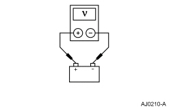 - Is the voltage between 13 and 15.2 volts?
| Yes
For DTC B1318 or U3003:16, GO to
R4
.
For DTC B1317 or U3003:17, GO to
R6
.
No
REFER to
Section 414-00
to diagnose the charging system. CLEAR all
. TEST the
for normal operation.
|
|
R4 CHECK FOR OPEN IGNITION CIRCUIT TO THE MODULE
|
|
- Ignition OFF.
- Depower the
. Refer to
Supplemental Restraint System (SRS) Depowering and Repowering
in this section.
- Disconnect:
C2041A and C2041B (if DTC U3003:16 or U3003:17 is present in the
).
- Disconnect:
C3043 (if DTC U3003:16 or U3003:17 is present in the
).
- For the
, measure the resistance between
C2041A-13, circuit CBP31 (BU/OG), harness side and Smart Junction Box (SJB) fuse 31.
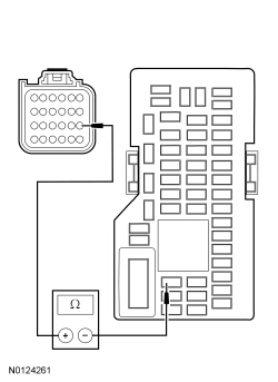 - For the
, measure the resistance between
C3043-1, circuit CBP46 (WH/BU), harness side and
fuse 46.
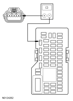 - Is the resistance less than 1 ohm?
| Yes
GO to
R5
.
No
REPAIR the circuit as necessary.
Refer to Wiring Diagrams Cell
5
, Connector Repair Procedures for schematic and connector information.
CLEAR all
. TEST the
for normal operation.
|
|
R5 CHECK FOR OPEN GROUND TO THE MODULE
|
|
- Measure the resistance of the ground circuit:
- For the
, measure the resistance between the
case and a good ground.
- For the
, measure the resistance between
C3043-4, circuit GD138 (BK/WH), harness side and ground.
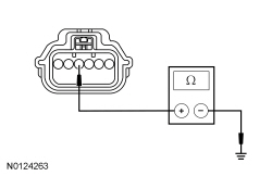 - Is the resistance less than 1 ohm?
| Yes
GO to
R6
.
No
For the
, VERIFY there is no corrosion between the
case and mounting. VERIFY the fasteners are clean and tightened to specification with no corrosion. REPAIR as necessary.
Refer to Wiring Diagrams Cell
5
, Connector Repair Procedures for schematic and connector information.
For the
, REPAIR circuit GD138 (BK/WH).
Refer to Wiring Diagrams Cell
5
, Connector Repair Procedures for schematic and connector information.
CLEAR all
. TEST the
for normal operation.
|
|
R6 CHECK FOR MODULE OPERATION
|
|
| Yes
INSTALL a new module. REFER to
Restraints Control Module (RCM)
or
Occupant Classification Sensor
in this section.
No
The system is operating correctly at this time. The concern may have been caused by a loose or corroded connector. CLEAR all
. TEST the
for normal operation.
|
Pinpoint Test S: DTCs B0001:2B, B0002:2B, B0010:2B, B0011:2B, B0020:2B, B0028:2B, B0050:2B, B0052:2B, B00B5:2B, B00C5:2B, B1211:2B and B1214:2B
Refer to Wiring Diagrams Cell
46
, Supplemental Restraint System for schematic and connector information.
Normal Operation
The Restraints Control Module (RCM) monitors all deployable device and sensor circuits for a signal cross coupled (short) between circuits. If the
detects a short between the circuits of one device and another device, it will store a DTC for each of the signal cross coupled faults in memory. The
sends a message to the Instrument Panel Cluster (IPC) to illuminate the air bag warning indicator. When a normal loop fault is present (one loop is either shorted to battery/ground, open circuit or low resistance), then signal cross coupled diagnostics will not be active. Once the normal loop fault is repaired, then the signal cross coupled diagnostics will resume.
| DTC Description
| Fault Trigger Condition
|
|---|
- B0001:2B — Driver Frontal Stage 1 Deployment Control: Signal Cross Coupled
| If the
detects a short between the driver air bag Stage 1 circuits and the circuits of another Supplemental Restraint System (SRS) component, it will set this DTC and the DTC of the corresponding
component.
|
- B0002:2B — Driver Frontal Stage 2 Deployment Control: Signal Cross Coupled
| If the
detects a short between the driver air bag Stage 2 circuits and the circuits of another Supplemental Restraint System (SRS) component, it will set this DTC and the DTC of the corresponding
component.
|
- B0010:2B — Passenger Frontal Stage 1 Deployment Control: Signal Cross Coupled
| If the
detects a short between the driver air bag Stage 1 circuits and the circuits of another Supplemental Restraint System (SRS) component, it will set this DTC and the DTC of the corresponding
component.
|
- B0011:2B — Passenger Frontal Stage 2 Deployment Control: Signal Cross Coupled
| If the
detects a short between the driver air bag Stage 2 circuits and the circuits of another Supplemental Restraint System (SRS) component, it will set this DTC and the DTC of the corresponding
component.
|
- B0020:2B — Left Side Airbag Deployment Control: Signal Cross Coupled
| If the
detects a short between the left side air bag circuits and the circuits of another
component, it will set this DTC and the DTC of the corresponding
component.
|
- B0028:2B — Right Side Airbag Deployment Control: Signal Cross Coupled
| If the
detects a short between the right side air bag circuits and the circuits of another
component, it will set this DTC and the DTC of the corresponding
component.
|
- B0050:2B — Driver Seatbelt Sensor: Signal Cross Coupled
| If the
detects a short between the driver safety belt sensor circuits and the circuits of another
component, it will set this DTC and the DTC of the corresponding
component.
|
- B0052:2B — Passenger Seatbelt Sensor: Signal Cross Coupled
| If the
detects a short between the passenger safety belt sensor circuits and the circuits of another
component, it will set this DTC and the DTC of the corresponding
component.
|
- B00B5:2B — Driver Seat Track Position Restraints Sensor: Signal Cross Coupled
| If the
detects a short between the driver seat track position sensor circuits and the circuits of another
component, it will set this DTC and the DTC of the corresponding
component.
|
- B00C5:2B — Passenger Seat Track Position Restraints Sensor: Signal Cross Coupled
| If the
detects a short between the passenger seat track position sensor circuits and the circuits of another
component, it will set this DTC and the DTC of the corresponding
component.
|
- B1211:2B — Driver Seatbelt Retractor Pretensioner Deployment Control: Signal Cross Coupled
| If the
detects a short between the driver safety belt retractor pretensioner circuits and the circuits of another
component, it will set this DTC and the DTC of the corresponding
component.
|
- B1214:2B — Passenger Seatbelt Retractor Pretensioner Deployment Control: Signal Cross Coupled
| If the
detects a short between the passenger safety belt retractor pretensioner circuits and the circuits of another
component, it will set this DTC and the DTC of the corresponding
component.
|
This pinpoint test is intended to diagnose the following:
- Wiring, terminals or connectors
PINPOINT TEST S: DTCs B0001:2B, B0002:2B, B0010:2B, B0011:2B, B0020:2B, B0028:2B, B0050:2B, B0052:2B, B00B5:2B, B00C5:2B, B1211:2B and B1214:2B
WARNING: Never probe the electrical connectors on airbag, Safety Canopy or side air curtain assemblies. Failure to follow this instruction may result in the accidental deployment of these assemblies, which increases the risk of serious personal injury or death.
WARNING: Never disassemble or tamper with seat belt deployable components, including pretensioners, load limiters and inflators. Never back probe deployable device electrical connectors. Tampering or back probing may cause an accidental deployment and result in personal injury or death.
NOTICE:
Use the correct probe adapter(s) from the Flex Probe Kit when taking measurements. Failure to use the correct probe adapter(s) may damage the connector.
Most faults are due to connector and/or wiring concerns. Carry out a thorough inspection and verification before proceeding with the pinpoint test.
NOTE:
The
must be fully operational and free of faults before releasing the vehicle to the customer.
NOTE:
components should only be disconnected or reconnected when instructed to do so within a pinpoint test step. Failure to follow this instruction may result in incorrect diagnosis of the
.
NOTE:
Always make sure the correct
component is being installed. Parts released for other vehicles may not be compatible even if they appear physically similar. Check the part number listed in the Ford Catalog Advantage™ or equivalent to make sure the correct component is being installed. If an incorrect
component is installed, DTCs may set.
| Test Step
| Result / Action to Take
|
|---|
|
S1 RETRIEVE
DTCs
|
|
- Enter the following diagnostic mode on the scan tool: Self Test —
.
- NOTE:
Signal cross coupled DTCs will be retrieved in pairs.
- Were any signal cross coupled DTCs retrieved on-demand during self-test?
| Yes
This fault cannot be cleared until it is corrected and the DTC is no longer retrieved on-demand during self-test. GO to
S2
.
No
This is an intermittent fault when present as a Continuous Memory Diagnostic Trouble Code (CMDTC) only. GO to
S4
.
|
|
S2 CHECK DEPLOYABLE CIRCUITS FOR A SIGNAL CROSS COUPLED FAULT
|
|
- Ignition OFF.
- Depower the
. Refer to
Supplemental Restraint System (SRS) Depowering and Repowering
in this section.
- Disconnect:
C2041A and C2041B .
- NOTE:
Most signal cross coupled faults are due to connector and/or wiring harness damage. Carry out a thorough inspection of connector(s) and/or wiring harness for damage.
- Disconnect
ALL of the affected
devices.
- Measure the resistance between the circuits of the affected
devices using the following table:
| Device/Loop/Squib (DTC)
| Connector
| Circuit
|
|---|
| Driver air bag module loop 1 (B0001:2B)
| - Driver air bag module loop 1 electrical connector
| - RR101 (YE/GN)
- CR101 (VT/BN)
| | Driver air bag module stage 2 (B0002:2B)
| - Driver air bag module loop 2 electrical connector
| | | Passenger air bag module stage 1 (B0010:2B)
| | - CR103 (GY/BU)
- RR103 (VT/GN)
| | Passenger air bag module stage 2 (B0011:2B)
| | - CR104 (YE/GY)
- RR104 (WH/BU)
| | Driver seat side air bag module (B0020:2B)
| | - CR105 (GN/BU)
- RR105 (GY/YE)
| | Passenger seat side air bag module (B0028:2B)
| | - CR106 (VT/GY)
- RR106 (YE/OG)
| | Driver safety belt buckle switch (B0050:2B)
| | | | Passenger safety belt buckle switch (B0052:2B)
| | | | Driver seat track position restraints sensor (B00B5:2B)
| | | | Passenger seat track position restraints sensor (B00C5:2B)
| | | | Driver safety belt retractor pretensioner (B1211:2B)
| | - CR120 (BU/OG)
- RR120 (BN/GN)
| | Passenger safety belt retractor pretensioner (B1214:2B)
| | |
- Are the resistances greater than 10,000 ohms between the affected circuits?
| Yes
GO to
S3
.
No
REPAIR the affected circuits.
Refer to Wiring Diagrams Cell
5
, Connector Repair Procedures for schematic and connector information.
GO to
S5
.
|
|
S3 CONFIRM THE
FAULT
|
|
NOTE:
Make sure all restraint system components and the
electrical connectors are connected before carrying out the self-test. If not, DTCs will be recorded.
- Prior to reconnecting any previously disconnected
component:
- inspect connector(s) (including any in-line connectors) for pushed out, loose or spread terminals and loose or frayed wire connections at terminals.
- inspect wire harness for any damage, pinched, cut or pierced wires.
- Connect: All Previously Disconnected Restraint System Component(s) .
- Connect:
C2041A and C2041B .
- Repower the
.
Do not
prove out the
at this time. Refer to
Supplemental Restraint System (SRS) Depowering and Repowering
in this section.
- Enter the following diagnostic mode on the scan tool: Self Test —
.
- Were any signal cross coupled DTCs retrieved on-demand during self-test?
| Yes
INSTALL a new
. REFER to
Restraints Control Module (RCM)
in this section. GO to
S5
.
No
In the process of diagnosing the fault, the fault condition has become intermittent.
Do not install any new
components at this time.
components should only be installed when directed to do so in the pinpoint test.
GO to
S4
.
|
|
S4 CHECK FOR AN INTERMITTENT FAULT
|
|
NOTE:
Most cross link faults are due to connector and/or wiring harness damage. Carry out a thorough inspection of connector(s) and/or wiring harness for damage.
- Ignition OFF.
- Depower the
. Refer to
Supplemental Restraint System (SRS) Depowering and Repowering
in this section.
- Disconnect
ALL of the affected
devices.
- Inspect the wiring harness(es) for any type of damage. Repair as necessary.
Refer to Wiring Diagrams Cell
5
, Connector Repair Procedures for schematic and connector information.
- Repower the
.
Do not
prove out the
at this time. Refer to
Supplemental Restraint System (SRS) Depowering and Repowering
in this section.
- Enter the following diagnostic mode on the scan tool: Self Test —
.
- Were any signal cross coupled DTCs retrieved on-demand during self-test?
| Yes
This is a hard fault. The fault condition is now present. This fault cannot be cleared until it is corrected and the DTC is no longer retrieved on-demand during self-test. GO to
S2
.
No
The fault is not present and cannot be recreated at this time.
CHECK for causes of the intermittent fault. ATTEMPT to recreate the hard fault by flexing the wire harness and cycling the ignition frequently.
Do not install any new
components at this time.
components should only be installed when directed to do so in the pinpoint test.
REPAIR any intermittent wiring, terminal or connector concerns found.
Refer to Wiring Diagrams Cell
5
, Connector Repair Procedures for schematic and connector information.
GO to
S5
.
|
|
S5 CHECK FOR ADDITIONAL
DTCs
|
|
- Ignition OFF.
- WARNING: Turn the ignition OFF and wait one minute to deplete the backup power supply. Failure to follow this instruction may result in serious personal injury or death in the event of an accidental deployment.
- Reconnect all
components (if previously disconnected).
- If previously directed to depower the
, repower the
.
Do not
prove out the
at this time. Refer to
Supplemental Restraint System (SRS) Depowering and Repowering
in this section.
- Ignition ON.
- Enter the following diagnostic mode on the scan tool: Self Test — Restraints .
- NOTE:
When selecting Restraints from the Self Test menu, DTCs will be retrieved from the
and Occupant Classification System Module (OCSM).
- Are any
and/or
DTCs retrieved on-demand during self-test?
| Yes
Do not clear any DTCs until all DTCs have been resolved. GO to the DTC Charts in this section for pinpoint test direction.
No
CLEAR all
and
. PROVE OUT the
. The repair is complete. RETURN the vehicle to the customer.
|
Pinpoint Test T: DTCs B0001:4A, B0002:4A, B0010:4A, B0011:4A, B0020:4A, B0028:4A, B0050:4A, B0052:4A, B0090:4A, B0091:4A, B0095:4A, B0096:4A, B00B5:4A, B00C5:4A, B00D5:4A, B1211:4A, B1214:4A and U3000:4A
Refer to Wiring Diagrams Cell
46
, Supplemental Restraint System for schematic and connector information.
Normal Operation
The Restraints Control Module (RCM) monitors all of Supplemental Restraint System (SRS) device connections. If the
detects a connection or device connected that is not stored in memory or is not configured for the component, the
will set a DTC and send a message to the Instrument Panel Cluster (IPC) to illuminate air bag warning indicator.
| DTC Description
| Fault Trigger Condition
|
|---|
- B0001:4A — Driver Frontal Stage 1 Deployment Control: Incorrect Component Installed
| This DTC will set if the
detects the device but not configured for this component.
|
- B0002:4A — Driver Frontal Stage 2 Deployment Control: Incorrect Component Installed
| This DTC will set if the
detects the device but not configured for this component.
|
- B0010:4A — Passenger Frontal Stage 1 Deployment Control: Incorrect Component Installed
| This DTC will set if the
detects the device but not configured for this component.
|
- B0011:4A — Passenger Frontal Stage 2 Deployment Control: Incorrect Component Installed
| This DTC will set if the
detects the device but not configured for this component.
|
- B0020:4A — Left Side Airbag Deployment Control: Incorrect Component Installed
| This DTC will set if the
detects the device but not configured for this component.
|
- B0028:4A — Right Side Airbag Deployment Control: Incorrect Component Installed
| This DTC will set if the
detects the device but not configured for this component.
|
- B0050:4A — Driver Seatbelt Sensor: Incorrect Component Installed
| This DTC will set if the
detects the device but not configured for this component.
|
- B0052:4A — Passenger Seatbelt Sensor: Incorrect Component Installed
| This DTC will set if the
detects the device but not configured for this component.
|
- B0090:4A — Left Frontal Restraints Sensor: Incorrect Component Installed
| This DTC will set if the
detects the device but not configured for this component.
|
- B0091:4A — Left Side Restraints Sensor 1: Incorrect Component Installed
| This DTC will set if the
detects the device but not configured for this component.
|
- B0095:4A — Right Frontal Restraints Sensor: Incorrect Component Installed
| This DTC will set if the
detects the device but not configured for this component.
|
- B0096:4A — Right Side Restraints Sensor 1: Incorrect Component Installed
| This DTC will set if the
detects the device but not configured for this component.
|
- B00B5:4A — Driver Seat Track Position Restraints Sensor: Incorrect Component Installed
| This DTC will set if the
detects the device but not configured for this component.
|
- B00C5:4A — Passenger Seat Track Position Restraints Sensor: Incorrect Component Installed
| This DTC will set if the
detects the device but not configured for this component.
|
- B00D5:4A — Restraint System Passenger Disable Indicator: Incorrect Component Installed
| This DTC will set if the
detects the device but not configured for this component.
|
- B1211:4A — Driver Seatbelt Retractor Pretensioner Deployment Control: Incorrect Component Installed
| This DTC will set if the
detects the device but not configured for this component.
|
- B1214:4A — Passenger Seatbelt Retractor Pretensioner Deployment Control: Incorrect Component Installed
| This DTC will set if the
detects the device but not configured for this component.
|
- U3000:4A — Control Module: Incorrect Component Installed
| This DTC will set if the
detects the incorrect vehicle ID or model year ID from the Occupant Classification System Module (OCSM) or ABS module.
|
This pinpoint test is intended to diagnose the following:
- Incorrect ABS
- Incorrect
- Incorrect
- not configured
PINPOINT TEST T: DTCs B0001:4A, B0002:4A, B0010:4A, B0011:4A, B0020:4A, B0028:4A, B0050:4A, B0052:4A, B0090:4A, B0091:4A, B0095:4A, B0096:4A, B00B5:4A, B00B5:4A, B00D5:4A, B1211:4A, B1214:4A and U3000:4A
WARNING: Never probe the electrical connectors on airbag, Safety Canopy or side air curtain assemblies. Failure to follow this instruction may result in the accidental deployment of these assemblies, which increases the risk of serious personal injury or death.
WARNING: Never disassemble or tamper with seat belt deployable components, including pretensioners, load limiters and inflators. Never back probe deployable device electrical connectors. Tampering or back probing may cause an accidental deployment and result in personal injury or death.
NOTE:
The
must be fully operational and free of faults before releasing the vehicle to the customer.
NOTE:
components should only be disconnected or reconnected when instructed to do so within a pinpoint test step. Failure to follow this instruction may result in incorrect diagnosis of the
.
NOTE:
Always make sure the correct
component is being installed. Parts released for other vehicles may not be compatible even if they appear physically similar. Check the part number listed in the Ford Catalog Advantage™ or equivalent to make sure the correct component is being installed. If an incorrect
component is installed, DTCs may set.
NOTE:
Most faults are due to connector and/or wiring concerns. Carry out a thorough inspection and verification before proceeding with the pinpoint test.
| Test Step
| Result / Action to Take
|
|---|
|
T1 RETRIEVE
DTCs
|
|
- Enter the following diagnostic mode on the scan tool: Self Test —
.
- Was any incorrect component installed DTCs retrieved on-demand during self-test?
| Yes
This fault cannot be cleared until it is corrected and the DTC is no longer retrieved on-demand during self-test. GO to
T2
.
No
This is an intermittent fault when present as a Continuous Memory Diagnostic Trouble Code (CMDTC) only. GO to
T6
.
|
|
T2 CHECK VEHICLE HISTORY
|
|
- Ignition OFF.
- Check the vehicle repair history.
- Has a new
or
been installed during this or a prior repair?
| Yes
GO to
T3
.
No
GO to
T5
.
|
|
T3 CHECK
AND
VEHICLE IDENTIFICATION PIDs
|
|
- Ignition ON.
- Enter the following diagnostic mode on the scan tool: DataLogger —
.
- View and record the following PID values:
- Enter the following diagnostic mode on the scan tool: DataLogger —
.
- View and record the following PID values:
- Verify the correct vehicle application.
- Do the PID values match the vehicle application?
| Yes
GO to
T4
.
No
INSTALL the correct
or
sensor. REFER to
Occupant Classification Sensor
in this section. GO to
T8
.
|
|
T4 CHECK ABS MODULE
|
|
- Ignition OFF.
- Check the part number on the ABS module against the part number listed in the Ford Catalog Advantage
TM
or equivalent.
- Does the part number on the ABS module match the part number listed in the Ford Catalog Advantage
TM
or equivalent?
| Yes
GO to
T5
.
No
INSTALL the correct or later equivalent ABS module. REFER to the ABS module Removal and Installation procedure in
Section 206-09
. GO to
T8
.
|
|
T5 CHECK
|
|
- Ignition ON.
- Carry out Programmable Module Installation (PMI) for the
. Use as-built data when carrying out
. Refer to
Section 418-01
.
- Enter the following diagnostic mode on the scan tool: Self Test —
.
- Was any
incorrect component installed DTCs retrieved on-demand during self-test?
| Yes
GO to
T6
.
No
Fault corrected. GO to
T8
.
|
|
T6 CONFIRM THE
FAULT
|
|
NOTE:
Make sure all restraint system components and the
electrical connectors are connected before carrying out the self-test. If not, DTCs will be recorded.
- Connect: All Previously Disconnected Component(s)/Connector(s) .
- Repower the
.
Do not
prove out the
at this time. Refer to
Supplemental Restraint System (SRS) Depowering and Repowering
in this section.
- Enter the following diagnostic mode on the scan tool: Self Test —
.
- Was any
incorrect component installed DTCs retrieved on-demand during self-test?
| Yes
INSTALL a new
. REFER to
Restraints Control Module (RCM)
in this section. GO to
T8
.
No
In the process of diagnosing the fault, the fault condition has become intermittent.
Do not install any new
components at this time.
components should only be installed when directed to do so in the pinpoint test.
REPAIR any intermittent wiring, terminal or connector concerns found.
Refer to Wiring Diagrams Cell
5
, Connector Repair Procedures for schematic and connector information.
GO to
T7
.
|
|
T7 CHECK FOR INCORRECT COMPONENT INSTALLED
|
|
- Enter the following diagnostic mode on the scan tool: Self Test —
.
- Was any incorrect component installed DTCs retrieved on-demand during self-test?
| Yes
INSTALL new
. REFER to
Restraints Control Module (RCM)
in this section. GO to
T8
.
No
CHECK for causes of the intermittent fault. ATTEMPT to recreate the hard fault by flexing the wire harness and cycling the ignition frequently. ACTIVATE other systems in the same wire harness.
Do not install any new
components at this time.
components should only be installed when directed to do so in the pinpoint test.
REPAIR any intermittent wiring, terminal or connector concerns found.
Refer to Wiring Diagrams Cell
5
, Connector Repair Procedures for schematic and connector information.
GO to
T8
.
|
|
T8 CHECK FOR ADDITIONAL
DTCs
|
|
- Ignition OFF.
- WARNING: Turn the ignition OFF and wait one minute to deplete the backup power supply. Failure to follow this instruction may result in serious personal injury or death in the event of an accidental deployment.
- Reconnect all
components (if previously disconnected).
- If previously directed to depower the
, repower the
.
Do not
prove out the
at this time. Refer to
Supplemental Restraint System (SRS) Depowering and Repowering
in this section.
- Ignition ON.
- Enter the following diagnostic mode on the scan tool: Self Test — Restraints .
- NOTE:
When selecting Restraints from the Self Test menu, DTCs will be retrieved from the
and
.
- Are any on-demand
and/or
DTCs retrieved?
| Yes
Do not clear any DTCs until all DTCs have been resolved. GO to the DTC Charts in this section for pinpoint test direction.
No
CLEAR all
and
. PROVE OUT the
. The repair is complete. RETURN the vehicle to the customer.
|
Pinpoint Test U: DTCs U0028:08 and U0028:88
Refer to Wiring Diagrams Cell
42
, Vehicle Dynamic Systems for schematic and connector information.
Normal Operation
The Restraints Control Module (RCM) supplies the stability/traction control system with the yaw rate, roll rate, lateral and longitudinal accelerometer over a dedicated Controller Area Network (CAN) bus. If the
detects a fault with communications with the ABS module or dedicated
bus circuits, it will set DTC U0028:08 or U0028:88.
The
does not request the Instrument Panel Cluster (IPC) to illuminate the air bag warning indicator if either DTC U0028:08 or U0028:88 is set.
- DTC U0028:08 (Vehicle Communication Bus A: Bus Signal / Message Failures) — When the
does not receive dedicated
bus messages from the ABS module for 5 seconds, a fault will be indicated. An open dedicated
circuit, incorrectly installed ABS module or loss of power and/or ground to the ABS module can set this DTC.
- DTC U0028:88 (Vehicle Communication Bus A: Bus Off) — When the
detects the dedicated
circuits are shorted to ground, shorted to voltage or shorted to each other, a fault will be indicated.
This pinpoint test is intended to diagnose the following:
- Wiring, terminals or connectors
- ABS module
PINPOINT TEST U: DTCs U0028:08 AND U0028:88
WARNING: Never probe the electrical connectors on airbag, Safety Canopy or side air curtain assemblies. Failure to follow this instruction may result in the accidental deployment of these assemblies, which increases the risk of serious personal injury or death.
WARNING: Never disassemble or tamper with seat belt deployable components, including pretensioners, load limiters and inflators. Never back probe deployable device electrical connectors. Tampering or back probing may cause an accidental deployment and result in personal injury or death.
NOTICE:
Use the correct probe adapter(s) from the Flex Probe Kit when taking measurements. Failure to use the correct probe adapter(s) may damage the connector.
Most faults are due to connector and/or wiring concerns. Carry out a thorough inspection and verification before proceeding with the pinpoint test.
NOTE:
Supplemental Restraint System (SRS) components should only be disconnected or reconnected when instructed to do so within a pinpoint test step. Failure to follow this instruction may result in incorrect diagnosis of the
.
NOTE:
Always make sure the correct
component is being installed. Parts released for other vehicles may not be compatible even if they appear physically similar. Check the part number listed in the Ford Catalog Advantage™ or equivalent to make sure the correct component is being installed. If an incorrect
component is installed, DTCs may set.
NOTE:
The
must be fully operational and free of faults before releasing the vehicle to the customer.
| Test Step
| Result / Action to Take
|
|---|
|
U1 RETRIEVE
DTCs
|
|
- Ignition ON.
- Enter the following diagnostic mode on the scan tool: Self Test —
.
- Was DTC U0028:08 or U0028:88 retrieved on-demand during self-test?
| Yes
This fault cannot be cleared until it is corrected and the DTC is no longer retrieved on-demand during self-test.
For DTC U0028:08, GO to
U2
.
For DTC U0028:88, GO to
U5
.
No
This is an intermittent fault when present as a Continuous Memory Diagnostic Trouble Code (CMDTC) only. GO to
U13
.
|
|
U2 CHECK FOR CORRECT
|
|
- Ignition OFF.
- WARNING: Turn the ignition OFF and wait one minute to deplete the backup power supply. Failure to follow this instruction may result in serious personal injury or death in the event of an accidental deployment.
- Access to the
. Refer to
Restraints Control Module (RCM)
in this section. Check the part number on the
against the number listed in the Ford Catalog Advantage™ or equivalent.
- Does the part number match?
| Yes
GO to
U3
.
No
INSTALL the correct
. REFER to
Restraints Control Module (RCM)
in this section. GO to
U14
.
|
|
U3 CHECK FOR CORRECT ABS MODULE
|
|
- Gain access to the ABS module. Check the part number on the ABS module against the part number listed in the Ford Catalog Advantage™ or equivalent.
- Does the part number match?
| Yes
GO to
U4
.
No
INSTALL the correct ABS module. REFER to
Section 206-09
. GO to
U14
.
|
|
U4 CHECK THE
COMMUNICATIONS (ABS MODULE COMMUNICATIONS)
|
|
- Ignition ON.
- Enter the following diagnostic mode on the scan tool: Network Test .
- NOTE:
The Network Test does not test the dedicated
communications between the ABS module and
.
- Did the Network Test pass (ABS module communicates with the scan tool)?
| Yes
GO to
U5
.
No
REFER to
Section 418-00
to diagnose the High Speed Controller Area Network (HS-CAN)/ABS module communication concern. GO to
U14
.
|
|
U5 CHECK THE DEDICATED
CIRCUITS FOR AN OPEN
|
|
- Ignition OFF.
- Depower the
. Refer to
Supplemental Restraint System (SRS) Depowering and Repowering
in this section.
- Disconnect:
C2041A and C2041B .
- Disconnect: ABS Module C135 .
- Measure the resistance between the ABS module C135, harness side and the
C2041B, harness side as indicated in the following chart:
| ABS Module
| Circuit
| |
|---|
| C135-8
| VCA23 (BU/WH)
| C2041B-20
| | C135-9
| VCA24 (GN/OG)
| C2041B-19
|
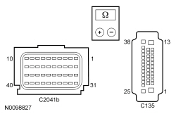 - Are the resistances less than 5 ohms?
| Yes
For DTC U0028:08, GO to
U9
.
For DTC U0028:88, GO to
U6
.
No
REPAIR circuits VCA24 (GN/OG) and VCA23 (BU/WH).
Refer to Wiring Diagrams Cell
5
, Connector Repair Procedures for schematic and connector information.
GO to
U14
.
|
|
U6 CHECK THE DEDICATED
CIRCUITS FOR A SHORT TO VOLTAGE
|
|
| Yes
REPAIR circuit VCA24 (GN/OG) or VCA23 (BU/WH).
Refer to Wiring Diagrams Cell
5
, Connector Repair Procedures for schematic and connector information.
GO to
U14
.
No
GO to
U7
.
|
|
U7 CHECK THE DEDICATED
CIRCUITS FOR A SHORT TO GROUND
|
|
- Ignition OFF.
- Measure the resistance between ABS module:
- C135-8, circuit VCA23 (BU/WH), harness side and ground.
- C135-9, circuit VCA24 (GN/OG), harness side and ground.
 - Are the resistances greater than 10,000 ohms?
| Yes
GO to
U8
.
No
REPAIR circuit VCA24 (GN/OG) or VCA23 (BU/WH).
Refer to Wiring Diagrams Cell
5
, Connector Repair Procedures for schematic and connector information.
GO to
U14
.
|
|
U8 CHECK FOR SHORT BETWEEN THE DEDICATED
CIRCUITS
|
|
- Measure the resistance between ABS module C135-8, circuit VCA23 (BU/WH), harness side and C135-9, circuit VCA24 (GN/OG), harness side.
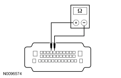 - Is the resistance greater than 10,000 ohms?
| Yes
GO to
U9
.
No
REPAIR circuits VCA24 (GN/OG) and VCA23 (BU/WH).
Refer to Wiring Diagrams Cell
5
, Connector Repair Procedures for schematic and connector information.
GO to
U14
.
|
|
U9 CHECK THE
TERMINATING RESISTOR
|
|
- Connect:
C2041B .
- Measure the resistance between ABS module C135-8, circuit VCA23 (BU/WH), harness side and C135-9, circuit VCA24 (GN/OG), harness side.
- Is the resistance between 108 and 132 ohms?
| Yes
GO to
U10
.
No
GO to
U11
.
|
|
U10 CHECK THE ABS MODULE TERMINATING RESISTOR
|
|
- Disconnect:
C2041B .
- Connect: ABS Module C135 .
- Measure the resistance between
C2041B-20, circuit VCA23 (BU/WH), harness side and C2041B-19, circuit VCA24 (GN/OG), harness side.
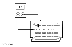 - Is the resistance between 108 and 132 ohms?
| Yes
For DTC U0028:08, GO to
U11
.
For DTC U0028:88, GO to
U12
.
No
GO to
U12
.
|
|
U11 CONFIRM THE
FAULT
|
|
NOTE:
Make sure all restraint system components, sensor electrical connectors and the
electrical connectors are connected before carrying out self-test. If not, DTCs will be recorded.
- If previously directed to repower the
, depower the
. Refer to
Supplemental Restraint System (SRS) Depowering and Repowering
in this section.
- Prior to reconnecting any previously disconnected
component:
- inspect connector(s) (including any in-line connectors) for pushed-out, loose or spread terminals and loose or frayed wire connections at terminals.
- inspect wire harness for any damage, pinched, cut or pierced wires.
- inspect ABS module C135 for dirt, corrosion, water intrusion, pushed-out, loose or spread terminals and loose or frayed wire connections at terminals.
- Connect: All Previously Disconnected Component(s)/Connector(s) .
- Repower the
.
Do not
prove out the
at this time. Refer to
Supplemental Restraint System (SRS) Depowering and Repowering
in this section.
- Enter the following diagnostic mode on the scan tool: Self Test —
.
- Was DTC U0028:08 retrieved on-demand during self-test?
| Yes
INSTALL a new
. REFER to
Restraints Control Module (RCM)
in this section. GO to
U14
.
No
In the process of diagnosing the fault, the fault condition has become intermittent.
Do not install any new
components at this time.
components should only be installed when directed to do so in the pinpoint test.
GO to
U13
.
|
|
U12 CONFIRM THE ABS MODULE FAULT
|
|
NOTE:
Make sure all restraint system components and the
electrical connectors are connected before carrying out self-test. If not, DTCs will be recorded.
- If previously directed to repower the
, depower the
. Refer to
Supplemental Restraint System (SRS) Depowering and Repowering
in this section.
- Prior to reconnecting any previously disconnected
component:
- inspect connector(s) (including any in-line connectors) for pushed-out, loose or spread terminals and loose or frayed wire connections at terminals.
- inspect wire harness for any damage, pinched, cut or pierced wires.
- inspect ABS module C135 for dirt, corrosion, water intrusion, pushed-out, loose or spread terminals and loose or frayed wire connections at terminals.
- Connect: All Previously Disconnected Component(s)/Connector(s) .
- Repower the
.
Do not
prove out the
at this time. Refer to
Supplemental Restraint System (SRS) Depowering and Repowering
in this section.
- Enter the following diagnostic mode on the scan tool: Self Test —
.
- Was DTC U0028:88 retrieved on-demand during self-test?
| Yes
INSTALL a new ABS module. REFER to the ABS Module Removal and Installation in
Section 206-09
. GO to
U14
.
No
In the process of diagnosing the fault, the fault condition has become intermittent.
Do not install any new
components at this time.
components should only be installed when directed to do so in the pinpoint test.
GO to
U13
.
|
|
U13 CHECK FOR AN INTERMITTENT FAULT
|
|
| Yes
This fault cannot be cleared until it is corrected and the DTC is no longer retrieved on-demand during self-test.
CHECK for causes of the intermittent fault in the areas previously worked in, particularly the pins and terminals of any electrical connector that were disconnected. REPAIR any intermittent wiring, terminal or connector concerns found.
Refer to Wiring Diagrams Cell
5
, Connector Repair Procedures for schematic and connector information.
GO to
U14
.
No
The fault is not present and cannot be recreated at this time.
Do not install any new
components at this time.
components should only be installed when directed to do so in the pinpoint test.
GO to
U14
.
|
|
U14 CHECK FOR ADDITIONAL
AND ABS MODULE DTCs
|
|
- Ignition OFF.
- WARNING: Turn the ignition OFF and wait one minute to deplete the backup power supply. Failure to follow this instruction may result in serious personal injury or death in the event of an accidental deployment.
- Reconnect all
components (if previously disconnected).
- If previously directed to depower the
, repower the
.
Do not
prove out the
at this time. Refer to
Supplemental Restraint System (SRS) Depowering and Repowering
in this section.
- Ignition ON.
- Enter the following diagnostic mode on the scan tool: Self Test —
.
- Enter the following diagnostic mode on the scan tool: Self Test — ABS Module .
- Are any DTCs retrieved from the
or ABS module during self-test?
| Yes
Do not clear any DTCs until all DTCs have been resolved. GO to the appropriate DTC Chart in this section and/or
Section 206-09
for pinpoint test direction.
No
CLEAR all
. PROVE OUT the
. The repair is complete. RETURN the vehicle to the customer.
|
Pinpoint Test V: DTCs B00C5:11, B00C5:12, B00C5:13 and B00C5:1D
Refer to Wiring Diagrams Cell
46
, Supplemental Restraint System for schematic and connector information.
Normal Operation
The Restraints Control Module (RCM) monitors the passenger seat track position sensor and circuits for the following faults:
- Short to ground
- Short to voltage
- Open circuit
- Current out of range
- Faulted passenger seat track position sensor
If a fault is detected, the
will store DTC B00C5:11, B00C5:12, B00C5:13 or B00C5:1D in memory and send a message to the Instrument Panel Cluster (IPC) to illuminate the air bag warning indicator.
| DTC Description
| Fault Trigger Condition
|
|---|
- B00C5:11 — Passenger Seat Track Position Restraints Sensor: Circuit Short to Ground
| When the
senses a short to ground on the passenger seat track position sensor circuit, a fault will be indicated.
|
- B00C5:12 — Passenger Seat Track Position Restraints Sensor: Circuit Short to Battery
| When the
senses a short to voltage on the passenger seat track position sensor circuit, a fault will be indicated.
|
- B00C5:13 — Passenger Seat Track Position Restraints Sensor: Circuit Open
| When the
senses an open on the passenger seat track position sensor circuit, a fault will be indicated. An open passenger seat track position sensor ground circuit will set this fault.
|
- B00C5:1D — Passenger Seat Track Position Restraints Sensor: Circuit Current Out of Range
| When the
senses current out of an acceptable range between the passenger seat track position sensor circuits, a fault will be indicated.
|
This pinpoint test is intended to diagnose the following:
- Wiring, terminals or connectors
- Passenger seat track position sensor
PINPOINT TEST V: DTCs B00C5:11, B00C5:12, B00C5:13 AND B00C5:1D
WARNING: Never disassemble or tamper with seat belt deployable components, including pretensioners, load limiters and inflators. Never back probe deployable device electrical connectors. Tampering or back probing may cause an accidental deployment and result in personal injury or death.
WARNING: Never probe the electrical connectors on airbag, Safety Canopy or side air curtain assemblies. Failure to follow this instruction may result in the accidental deployment of these assemblies, which increases the risk of serious personal injury or death.
NOTICE:
Use the correct probe adapter(s) from the Flex Probe Kit when taking measurements. Failure to use the correct probe adapter(s) may damage the connector.
Most faults are due to connector and/or wiring concerns. Carry out a thorough inspection and verification before proceeding with the pinpoint test.
NOTE:
Supplemental Restraint System (SRS) components should only be disconnected or reconnected when instructed to do so within a pinpoint test step. Failure to follow this instruction may result in incorrect diagnosis of the
.
NOTE:
Always make sure the correct
component is being installed. Parts released for other vehicles may not be compatible even if they appear physically similar. Check the part number listed in the Ford Catalog Advantage™ or equivalent to make sure the correct component is being installed. If an incorrect
component is installed, DTCs may set.
NOTE:
The
must be fully operational and free of faults before releasing the vehicle to the customer.
| Test Step
| Result / Action to Take
|
|---|
|
V1 RETRIEVE
DTCs
|
|
- Enter the following diagnostic mode on the scan tool: Self Test —
.
- Was DTC B00C5:11, B00C5:12, B00C5:13 or B00C5:1D retrieved on-demand during self-test?
| Yes
This fault cannot be cleared until it is corrected and the DTC is no longer retrieved on-demand during self-test.
For DTC B00C5:11 or B00C5:1D, GO to
V2
.
For DTC B00C5:12, GO to
V4
.
For DTC B00C5:13, GO to
V5
.
No
This is an intermittent fault when present as a Continuous Memory Diagnostic Trouble Code (CMDTC) only. GO to
V10
.
|
|
V2 CHECK THE PASSENGER SEAT TRACK POSITION RESTRAINTS SENSOR DTC FOR A FAULT STATUS CHANGE (SHORT TO GROUND OR CURRENT OUT OF RANGE INDICATED)
|
|
NOTE:
This pinpoint test step will attempt to change the fault reported by the
by inducing a different fault condition. If the fault reported changes, this indicates the
is functioning correctly and is not the source of the fault.
- Ignition OFF.
- WARNING: Turn the ignition OFF and wait one minute to deplete the backup power supply. Failure to follow this instruction may result in serious personal injury or death in the event of an accidental deployment.
- Disconnect: Passenger Seat Track Position Sensor C3240 .
- Ignition ON.
- Enter the following diagnostic mode on the scan tool: Self Test —
.
- DIAGNOSTIC TIP:
When viewing DTCs with the passenger seat track position sensor disconnected, an open circuit fault would normally be retrieved.
- Did the on-demand DTC change from B00C5:11 or B00C5:1D to B00C5:13?
| Yes
GO to
V8
.
No
For DTC B00C5:1D, GO to
V9
.
For DTC B00C5:11, GO to
V3
.
|
|
V3 CHECK THE PASSENGER SEAT TRACK POSITION SENSOR CIRCUIT FOR A SHORT TO GROUND
|
|
- Ignition OFF.
- Depower the
. Refer to
Supplemental Restraint System (SRS) Depowering and Repowering
in this section.
- Disconnect:
C2041A and C2041B .
- Measure the resistance between passenger seat track position sensor C3240-2, circuit VR216 (GN/OG), harness side and ground.
- Is the resistance greater than 10,000 ohms?
| Yes
GO to
V9
.
No
REPAIR circuit VR216 (GN/OG).
Refer to Wiring Diagrams Cell
5
, Connector Repair Procedures for schematic and connector information.
GO to
V11
.
|
|
V4 CHECK THE PASSENGER SEAT TRACK POSITION SENSOR CIRCUIT FOR A SHORT TO VOLTAGE
|
|
| Yes
REPAIR circuit VR216 (GN/OG).
Refer to Wiring Diagrams Cell
5
, Connector Repair Procedures for schematic and connector information.
GO to
V11
.
No
GO to
V9
.
|
|
V5 CHECK THE PASSENGER SEAT TRACK POSITION RESTRAINTS SENSOR DTC FOR A FAULT STATUS CHANGE (OPEN INDICATED)
|
|
NOTE:
This pinpoint test step will attempt to change the fault reported by the
by inducing a different fault condition. If the fault reported changes, this indicates the
is functioning correctly and is not the source of the fault.
- Ignition OFF.
- Depower the
. Refer to
Supplemental Restraint System (SRS) Depowering and Repowering
in this section.
- Disconnect: Passenger Seat Side Air Bag Module C337 .
- Disconnect: Passenger Seat Track Position Sensor C3240 .
- Connect a fused jumper wire between passenger seat track position sensor C3240-2, circuit VR216 (GN/OG), harness side and C3240-1, circuit GD138 (BK/WH), harness side.
- Repower the
.
Do not
prove out the system at this time. Refer to
Supplemental Restraint System (SRS) Depowering and Repowering
in this section.
- Ignition ON.
- Enter the following diagnostic mode on the scan tool: Self Test —
.
- DIAGNOSTIC TIP:
When viewing DTCs with the passenger seat track position sensor circuits shorted together, a short to ground fault would normally be retrieved.
- Did the on-demand DTC change from B00C5:13 to B00C5:11?
| Yes
GO to
V8
.
No
GO to
V6
.
|
|
V6 CHECK THE PASSENGER SEAT TRACK POSITION SENSOR CIRCUIT FOR AN OPEN
|
|
- Ignition OFF.
- Depower the
. Refer to
Supplemental Restraint System (SRS) Depowering and Repowering
in this section.
- Disconnect:
C2041A and C2041B .
- Remove the fused jumper wire from the passenger seat track position sensor C3240.
- Measure the resistance between
C2041B-31, circuit VR216 (GN/OG), harness side and passenger seat track position sensor C3240-2, circuit VR216 (GN/OG), harness side.
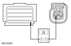 - Is the resistance less than 0.5 ohm?
| Yes
GO to
V7
.
No
REPAIR circuit VR216 (GN/OG).
Refer to Wiring Diagrams Cell
5
, Connector Repair Procedures for schematic and connector information.
GO to
V11
.
|
|
V7 CHECK THE PASSENGER SEAT TRACK POSITION SENSOR GROUND CIRCUIT FOR AN OPEN
|
|
- Measure the resistance between passenger seat track position sensor C3240-1, circuit GD138 (BK/WH), harness side, and ground.
- Is the resistance less than 5 ohm?
| Yes
GO to
V9
.
No
REPAIR circuit GD138 (BK/WH).
Refer to Wiring Diagrams Cell
5
, Connector Repair Procedures for schematic and connector information.
GO to
V11
.
|
|
V8 CONFIRM THE PASSENGER SEAT TRACK POSITION SENSOR FAULT
|
|
NOTE:
Make sure all restraint system components and the
electrical connectors are connected before carrying out the self-test. If not, DTCs will be recorded.
- Ignition OFF.
- Depower the
. Refer to
Supplemental Restraint System (SRS) Depowering and Repowering
in this section.
- If previously installed, remove the fused jumper wire from passenger seat track position sensor C3240.
- Prior to reconnecting any previously disconnected
component:
- inspect connector(s) (including any in-line connectors) for pushed-out, loose or spread terminals and loose or frayed wire connections at terminals.
- inspect wire harness for any damage, pinched, cut or pierced wires.
- Connect: All Previously Disconnected Components/Connectors .
- Repower the
.
Do not
prove out the
at this time. Refer to
Supplemental Restraint System (SRS) Depowering and Repowering
in this section.
- Ignition ON.
- Enter the following diagnostic mode on the scan tool: Self Test —
.
- Was the original DTC retrieved on-demand during self-test?
| Yes
INSTALL a new passenger seat track position sensor. REFER to
Seat Position Sensor
in this section. GO to
V11
.
No
In the process of diagnosing the fault, the fault condition has become intermittent.
Do not install any new
components at this time.
components should only be installed when directed to do so in the pinpoint test.
GO to
V10
.
|
|
V9 CONFIRM THE
FAULT
|
|
NOTE:
Make sure all restraint system components and the
electrical connectors are connected before carrying out the self-test. If not, DTCs will be recorded.
- Ignition OFF.
- Depower the
. Refer to
Supplemental Restraint System (SRS) Depowering and Repowering
in this section.
- Prior to reconnecting any previously disconnected
component:
- inspect connector(s) (including any in-line connectors) for pushed-out, loose or spread terminals and loose or frayed wire connections at terminals.
- inspect wire harness for any damage, pinched, cut or pierced wires.
- Connect: All Previously Disconnected Components/Connectors .
- Repower the
.
Do not
prove out the
at this time. Refer to
Supplemental Restraint System (SRS) Depowering and Repowering
in this section.
- Ignition ON.
- Enter the following diagnostic mode on the scan tool: Self Test —
.
- Was the original DTC retrieved on-demand during self-test?
| Yes
INSTALL a new
. REFER to
Restraints Control Module (RCM)
in this section. GO to
V11
.
No
In the process of diagnosing the fault, the fault condition has become intermittent.
Do not install any new
components at this time.
components should only be installed when directed to do so in the pinpoint test.
GO to
V10
.
|
|
V10 CHECK FOR AN INTERMITTENT FAULT
|
|
| Yes
This fault cannot be cleared until it is corrected and the DTC is no longer retrieved on-demand during self-test.
For DTC B00C5:11 or B00C5:1D, GO to
V2
.
For DTC B00C5:12, GO to
V4
.
For DTC B00C5:13, GO to
V5
.
No
The fault is not present and cannot be recreated at this time.
Do not install any new
components at this time.
components should only be installed when directed to do so in the pinpoint test.
GO to
V11
.
|
|
V11 CHECK FOR ADDITIONAL
DTCs
|
|
- Ignition OFF.
- WARNING: Turn the ignition OFF and wait one minute to deplete the backup power supply. Failure to follow this instruction may result in serious personal injury or death in the event of an accidental deployment.
- Reconnect all
components (if previously disconnected).
- If previously directed to depower the
, repower the
.
Do not
prove out the
at this time. Refer to
Supplemental Restraint System (SRS) Depowering and Repowering
in this section.
- Ignition ON.
- Enter the following diagnostic mode on the scan tool: Self Test — Restraints .
- NOTE:
When selecting Restraints from the Self Test menu, DTCs will be retrieved from the
and
.
- Are any
and/or
DTCs retrieved on-demand during self-test?
| Yes
Do not clear any DTCs until all DTCs have been resolved. GO to the DTC Charts in this section for pinpoint test direction.
No
CLEAR all
and
. PROVE OUT the
. The repair is complete. RETURN the vehicle to the customer.
|
Pinpoint Test W: DTC U0253:00
Diagnostic Overview
Diagnostics in this manual assume a certain skill level and knowledge of Ford-specific diagnostic practices. Refer to Diagnostic Methods in
Section 100-00
for information about these practices.
Refer to Wiring Diagrams Cell
46
, Supplemental Restraint System for schematic and connector information.
Normal Operation and Fault Conditions
The
uses information contained in messages from the
sent on the
.
- DTC U0253:00 (Lost Communication With Accessory Protocol Interface Module: No Sub Type Information) — This DTC sets if the
does not receive an expected message from the
for 6 seconds.
Possible Sources
- Network traffic
PINPOINT TEST W: DTC U0253:00
WARNING: Do not handle, move or change the original horizontal mounting position of the restraints control module (RCM) while the RCM is connected and the ignition switch is ON. Failure to follow this instruction may result in the accidental deployment of the Safety Canopy and cause serious personal injury or death.
NOTE:
Most faults are due to connector and/or wiring concerns. Carry out a thorough inspection and verification before proceeding with the pinpoint test.
NOTE:
components should only be disconnected or reconnected when instructed to do so within a pinpoint test step. Failure to follow this instruction may result in incorrect diagnosis of the
.
NOTE:
Always make sure the correct
component is being installed. Parts released for other vehicles may not be compatible even if they appear physically similar. Check the part number listed in the Ford Catalog Advantage™ or equivalent to make sure the correct component is being installed. If an incorrect
component is installed, DTCs may set.
NOTE:
The
must be fully operational and free of faults before releasing the vehicle to the customer.
| Test Step
| Result / Action to Take
|
|---|
|
W1 CHECK THE COMMUNICATION NETWORK
|
|
- Ignition ON.
- Enter the following diagnostic mode on the scan tool: Network Test.
- Does the
pass the network test?
| Yes
GO to
W2
.
No
REFER to
Section 418-00
to diagnose no communication with the
.
|
|
W2 CHECK THE
|
|
- Ignition ON.
- Enter the following diagnostic mode on the scan tool: Self Test —
.
- Enter the following diagnostic mode on the scan tool: Clear All
.
- Wait 10 seconds.
- Enter the following diagnostic mode on the scan tool: Self Test —
.
- Is DTC U0253:00 retrieved again?
| Yes
GO to
W3
.
No
The system is operating correctly at this time. The DTC may have been set due to high network traffic or an intermittent fault condition.
|
|
W3 RETRIEVE THE RECORDED DTCs FROM THE
SELF-TEST
|
|
- Check for recorded DTCs from the
self-test.
- Is DTC U3003:16 or U3003:17 recorded?
| Yes
REFER to the
DTC Chart to diagnose the
DTCs.
No
GO to
W4
.
|
|
W4 RETRIEVE THE RECORDED DTCs FROM THE
SELF-TEST
|
|
- Check for recorded DTCs from the
self-test.
- Is DTC U3003:16 or U3003:17 recorded?
| Yes
Diagnose the
DTCs. Refer to the appropriate section in Group
415
for the procedure.
No
CHECK
for any applicable TSBs. If a TSB exists for this concern, discontinue this test and follow TSB instructions. If no TSBs address this concern, INSTALL a new
. REFER to
Section 415-00
.
CLEAR the
DTCs and REPEAT the
self-test. If DTC U0253:00 is retreived again, INSTALL a new
. REFER to
Restraints Control Module (RCM)
.
|
Pinpoint Test — Occupant Classification System Module (OCSM)
Pinpoint Test X: DTCs B2290 and/or C1941
Refer to Wiring Diagrams Cell
46
, Supplemental Restraint System for schematic and connector information.
Normal Operation
The Occupant Classification System Module (OCSM) monitors the pressure sensor and internal circuitry for faults. If a fault is detected, the
stores DTC B2290 in memory and sends a message to the Restraints Control Module (RCM). The
then stores DTC B00A0:09 in memory and sends a message to the Instrument Panel Cluster (IPC) to illuminate the air bag warning indicator.
The Occupant Classification System (OCS) components
must not
be installed separate from the seat cushion or heater mat (if equipped).
DTC C1941 sets when System Reset fails to complete the testing. DTC C1941 will clear upon a successful System Reset.
- DTC B2290 Occupant Classification System (OCS) Fault — This DTC sets if the
detects a fault in the bladder pressure sensor (integrated with the
).
- DTC C1941 Zero Seat Weight Test Failure — This DTC will set if the
is unable to complete a successful System Reset. All other
DTCs must be diagnosed and repaired before carrying out the
reset.
This pinpoint test is intended to diagnose the following:
- Wiring, terminals or connectors
- Faulted
- bladder installation
PINPOINT TEST X: DTCs B2290 AND/OR C1941
WARNING: Never probe the electrical connectors on airbag, Safety Canopy or side air curtain assemblies. Failure to follow this instruction may result in the accidental deployment of these assemblies, which increases the risk of serious personal injury or death.
WARNING: Never disassemble or tamper with seat belt deployable components, including pretensioners, load limiters and inflators. Never back probe deployable device electrical connectors. Tampering or back probing may cause an accidental deployment and result in personal injury or death.
NOTICE:
Use the correct probe adapter(s) from the Flex Probe Kit when taking measurements. Failure to use the correct probe adapter(s) may damage the connector.
Most faults are due to connector and/or wiring concerns. Carry out a thorough inspection and verification before proceeding with the pinpoint test.
NOTE:
The Supplemental Restraint System (SRS) must be fully operational and free of faults before releasing the vehicle to the customer.
NOTE:
components should only be disconnected or reconnected when instructed to do so within a pinpoint test step. Failure to follow this instruction may result in incorrect diagnosis of the
.
NOTE:
Always make sure the correct
component is being installed. Parts released for other vehicles may not be compatible even if they appear physically similar. Check the part number listed in the Ford Catalog Advantage™ or equivalent to make sure the correct component is being installed. If an incorrect
component is installed, DTCs may set.
| Test Step
| Result / Action to Take
|
|---|
|
X1 RETRIEVE
DTCs
|
|
- Enter the following diagnostic mode on the scan tool: Self Test —
.
- Was DTC B2290 or C1941 retrieved during self-test?
| Yes
This fault cannot be cleared until it is corrected and the DTC is no longer retrieved on-demand during self-test.
If DTC C1941 was retrieved, GO to
X2
.
If DTC B2290 was retrieved, GO to
X4
.
No
This is an intermittent fault when present as a Continuous Memory Diagnostic Trouble Code (CMDTC) only. GO to
X5
.
|
|
X2 CHECK SEAT WIRING AND CONNECTORS
|
|
- Ignition OFF.
- WARNING: Turn the ignition OFF and wait one minute to deplete the backup power supply. Failure to follow this instruction may result in serious personal injury or death in the event of an accidental deployment.
- Carry out a thorough inspection of the
wiring, terminals and connectors and the related seat wiring harness and body wiring harness terminals and connectors.
- Were any problems noted?
| Yes
DEPOWER the
and REPAIR the seat connectors and wiring as needed.
Refer to Wiring Diagrams Cell
5
, Connector Repair Procedures for schematic and connector information.
GO to
X3
.
No
GO to
X3
.
|
|
X3 CHECK
|
|
NOTE:
Make sure all
components, restraint system components and the
electrical connectors are connected before carrying out the
Reset. If not, DTCs will be recorded.
- Enter the following diagnostic mode on the scan tool:
Reset.
- WARNING: Make sure the front passenger seat repair is complete, the seat and all attached components (head restraint, seat side shield, etc.) are correctly assembled, and the seat is correctly installed to the vehicle before using System Reset to rezero the seat weight. Failure to follow these instructions may result in incorrect operation of the occupant classification system (OCS) and increases the risk of serious personal injury or death in a crash.
- NOTICE:
To prevent system failure, the following precautions must be taken before carrying out the Occupant Classification System (OCS) reset:
- Make sure the
components are connected and no Occupant Classification System Module (OCSM) faults are present, with the exception of DTC C1941. All other
DTCs must be diagnosed and repaired before carrying out the
reset.
- Make sure the voltage to the
is above 8 volts and less than 18 volts.
- Make sure the
is not at a temperature below 6°C (42°F) or above 36°C (97°F) when initiating the
reset process. If the vehicle has been exposed to extreme cold or hot temperatures, the vehicle must be exposed and kept at a temperature within the limits, 6°C to 36°C (42°F to 97°F) for a minimum of 30 minutes.
- Make sure nothing is present on the passenger seat before carrying out the
reset and nothing is placed on the seat during the process.
- Make sure a minimum 8-second time period has passed after cycling the ignition switch ON before the carrying out the
reset process.
- Carry out the
reset.
- If the first system reset attempt was unsuccessful, carry out a thorough inspection of the following and repair any concerns found.
- Carry out a second
reset.
- Ignition OFF.
- Ignition ON.
- Enter the following diagnostic mode on the scan tool: Self Test —
.
- Was DTC C1941 retrieved on-demand during self-test?
| Yes
GO to
X4
.
No
Fault corrected. GO to
X6
.
|
|
X4 CONFIRM THE
FAULT
|
|
NOTE:
Make sure all
components, restraint system components, sensor electrical connectors and the
electrical connectors are connected before carrying out self-test. If not, DTCs will be recorded.
- Ignition OFF.
- WARNING: Turn the ignition OFF and wait one minute to deplete the backup power supply. Failure to follow this instruction may result in serious personal injury or death in the event of an accidental deployment.
- Prior to reconnecting any previously disconnected
component:
- Connect: All Previously Disconnected Component(s)/Connector(s).
- Enter the following diagnostic mode on the scan tool: Self Test —
.
- Was DTC B2290 or C1941 retrieved on-demand during self-test?
| Yes
INSTALL a new
sensor. REFER to
Occupant Classification Sensor
in this section. GO to
X6
.
No
In the process of diagnosing the fault, the fault condition has become intermittent.
Do not install any new
components at this time.
components should only be installed when directed to do so in the pinpoint test.
GO to
X5
.
|
|
X5 CHECK FOR AN INTERMITTENT FAULT
|
|
- Enter the following diagnostic mode on the scan tool: Self Test —
.
- Was DTC C1941 retrieved during self-test?
| Yes
This fault cannot be cleared until it is corrected and the DTC is no longer retrieved on-demand during self-test.
CHECK for causes of the intermittent fault at or near the affected
component connector. REPAIR any intermittent wiring, terminal or connector concerns found.
Refer to Wiring Diagrams Cell
5
, Connector Repair Procedures for schematic and connector information.
If an intermittent concern
was
found and repaired, INSPECT the seat wiring harness for damage and REPAIR as needed.
Refer to Wiring Diagrams Cell
5
, Connector Repair Procedures for schematic and connector information.
If OK, INSTALL a new
sensor. REFER to
Occupant Classification Sensor
in this section. GO to
X6
.
No
CHECK for causes of the intermittent fault. ATTEMPT to recreate the hard fault by flexing the wire harness and cycling the ignition frequently. ACTIVATE other systems in the same wire harness.
Do not install any new
components at this time.
components should only be installed when directed to do so in the pinpoint test.
REPAIR any intermittent wiring, terminal or connector concerns found.
Refer to Wiring Diagrams Cell
5
, Connector Repair Procedures for schematic and connector information.
GO to
X6
.
|
|
X6 CHECK FOR ADDITIONAL
DTCs
|
|
- Ignition OFF.
- WARNING: Turn the ignition OFF and wait one minute to deplete the backup power supply. Failure to follow this instruction may result in serious personal injury or death in the event of an accidental deployment.
- Reconnect all
components (if previously disconnected).
- If previously directed to depower the
, repower the
.
Do not
prove out the
at this time. Refer to
Supplemental Restraint System (SRS) Depowering and Repowering
in this section.
- Ignition ON.
- Enter the following diagnostic mode on the scan tool: Self Test — Restraints.
- NOTE:
When selecting Restraints from the Self Test menu, DTCs will be retrieved from the
and
.
- Are any on-demand
and/or
DTCs retrieved?
| Yes
Do not clear any DTCs until all DTCs have been resolved. GO to the DTC Charts in this section for pinpoint test direction.
No
CLEAR all
and
. PROVE OUT the
. The repair is complete. RETURN the vehicle to the customer.
|
Pinpoint Test Y: DTC B2909
Refer to Wiring Diagrams Cell
46
, Supplemental Restraint System for schematic and connector information.
Normal Operation
The Belt Tension Sensor (BTS) operates in conjunction with the Occupant Classification System (OCS). The
interprets a variable voltage signal provided by the
to identify the possible presence of a child safety seat in the front passenger seat. The voltage output of the
is proportional to the amount of tension applied to the sensor by the belt, no-tension low voltage (approximately 0.95 volt), high-tension high voltage (approximately 3.8 volts).
The Occupant Classification System Module (OCSM) monitors the
and all circuitry for faults. If a fault is detected, the
stores DTC B2909 in memory and sends a message to the Restraints Control Module (RCM). The
then sets DTC B00A0:68 and sends a message to the Instrument Panel Cluster (IPC) to illuminate the air bag warning indicator.
NOTE:
Do not mistake status information displayed with DTCs for fault PID information. Fault PIDs are only retrieved in the DataLogger function of the scan tool.
| Fault PIDs
a
| Description
| Fault Trigger Condition
|
|---|
| 2909_29_OD and 2909_29_CM
| Front Passenger Side Belt Tension Sensor Short to Ground
| When the
senses a short to ground on the
circuits, a fault is indicated.
|
| 2909_31_OD and 2909_31_CM
| Front Passenger Side Belt Tension Sensor Circuit Fault
| When the
senses a failure on the
circuits, a fault is indicated.
|
| 2909_30_OD and 2909_30_CM
| Front Passenger Side Belt Tension Sensor Circuit Open
| When the
senses an open on the
circuits, a fault is indicated.
|
| 2909_28_OD and 2909_28_CM
| Front Passenger Side Belt Tension Sensor Circuit Short to Battery
| When the
senses a short to voltage on the
signal circuit, a fault is indicated.
|
a
Fault PIDs that end in OD indicate on-demand status and are associated with DTC B2909. Fault PIDs that end in CM indicate continuous memory status and are associated with DTC B2909.
This pinpoint test is intended to diagnose the following:
- Wiring, terminals or connectors
- (part of RH front safety belt retractor)
PINPOINT TEST Y: DTC B2909
WARNING: Never probe the electrical connectors on airbag, Safety Canopy or side air curtain assemblies. Failure to follow this instruction may result in the accidental deployment of these assemblies, which increases the risk of serious personal injury or death.
WARNING: Never disassemble or tamper with seat belt deployable components, including pretensioners, load limiters and inflators. Never back probe deployable device electrical connectors. Tampering or back probing may cause an accidental deployment and result in personal injury or death.
NOTICE:
Use the correct probe adapter(s) from the Flex Probe Kit when taking measurements. Failure to use the correct probe adapter(s) may damage the connector.
Most faults are due to connector and/or wiring concerns. Carry out a thorough inspection and verification before proceeding with the pinpoint test.
NOTE:
Supplemental Restraint System (SRS) components should only be disconnected or reconnected when instructed to do so within a pinpoint test step. Failure to follow this instruction may result in incorrect diagnosis of the
.
NOTE:
Always make sure the correct
component is being installed. Parts released for other vehicles may not be compatible even if they appear physically similar. Check the part number listed in the Ford Catalog Advantage™ or equivalent to make sure the correct component is being installed. If an incorrect
component is installed, DTCs may set.
NOTE:
The
must be fully operational and free of faults before releasing the vehicle to the customer.
| Test Step
| Result / Action to Take
|
|---|
|
Y1 RETRIEVE
DTCs
|
|
| Yes
This fault cannot be cleared until it is corrected and the DTC is no longer retrieved on-demand during self-test.
For fault PID 2909_31_OD, GO to
Y2
.
For fault PID 2909_28_OD, GO to
Y8
.
For fault PID 2909_30_OD, GO to
Y9
.
For fault PID 2909_29_OD, GO to
Y10
.
No
This is an intermittent fault when present as a Continuous Memory Diagnostic Trouble Code (CMDTC) only. GO to
Y14
.
|
|
Y2 CHECK
CIRCUITS FOR A SHORT TO VOLTAGE
|
|
| Yes
REPAIR the affected circuit(s).
Refer to Wiring Diagrams Cell
5
, Connector Repair Procedures for schematic and connector information.
GO to
Y15
.
No
GO to
Y3
.
|
|
Y3 CHECK
CIRCUITS FOR AN OPEN
|
|
- Ignition OFF.
- Measure the resistance between
C3043-4, circuit GD138 (BK/WH), harness side and ground.
- Measure the resistance between
C3043, harness side and
C3238, harness side using the following chart:
| Circuit
| |
|---|
| C3043-5
| LR142 (YE/BU)
| C3238-1
| | C3043-6
| VR210 (BU/BN)
| C3238-3
|
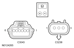 - Are the resistances less than 0.5 ohm?
| Yes
GO to
Y4
.
No
REPAIR the affected circuit(s).
Refer to Wiring Diagrams Cell
5
, Connector Repair Procedures for schematic and connector information.
GO to
Y15
.
|
|
Y4 CHECK
VREF AND SIGNAL CIRCUITS FOR A SHORT TO GROUND
|
|
- Measure the resistance between
:
- C3043-5, circuit LR142 (YE/BU), harness side and ground.
- C3043-6, circuit VR210 (BU/BN), harness side and ground.
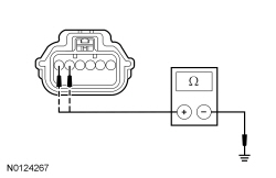 - Are the resistances greater than 10,000 ohms?
| Yes
GO to
Y5
.
No
REPAIR the affected circuit(s).
Refer to Wiring Diagrams Cell
5
, Connector Repair Procedures for schematic and connector information.
GO to
Y15
.
|
|
Y5 CHECK FOR A SHORT BETWEEN
CIRCUITS
|
|
- Measure the resistance between
:
- C3238-3, circuit VR210 (BU/BN), harness side and C3238-1, circuit LR142 (YE/BU), harness side.
- C3238-3, circuit VR210 (BU/BN), harness side and C3238-2, circuit GD138 (BK/WH), harness side.
- C3238-1, circuit LR142 (YE/BU), harness side and C3238-2, circuit GD138 (BK/WH), harness side.
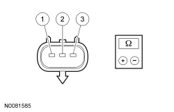 - Are the resistances greater than 10,000 ohms?
| Yes
GO to
Y6
.
No
REPAIR the affected circuits.
Refer to Wiring Diagrams Cell
5
, Connector Repair Procedures for schematic and connector information.
GO to
Y11
.
|
|
Y6 CHECK
OUTPUT
|
|
- Connect:
C3043 .
- Ignition ON.
- Measure the voltage between
C3238-1, circuit LR142 (YE/BU), harness side and C3238-2, circuit GD138 (BK/WH), harness side.
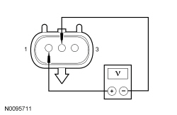 - Is the voltage approximately 5 volts?
| Yes
GO to
Y7
.
No
INSTALL a new
sensor. REFER to
Occupant Classification Sensor
in this section. GO to
Y15
.
|
|
Y7 CHECK
VOLTAGE OUTPUT
|
|
- Ignition OFF.
- Connect a fused jumper wire between
C3238-1, circuit LR142 (YE/BU), harness side and C3238 pin 1, component side.
- Connect a fused jumper wire between
C3238-2, circuit GD138 (BK/WH), harness side and C3238 pin 2, component side.
- Ignition ON.
- Measure the voltage between
C3238 pin 1, circuit VR210 (BU/BN), component side and ground as the tension of the
varies by pulling upward at the safety belt webbing.
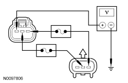 - Does the voltage vary from approximately 0.95 volt with no tension applied to the sensor to approximately 3.8 volts with full tension applied to the sensor?
| Yes
INSTALL a new
sensor. REFER to
Occupant Classification Sensor
in this section. GO to
Y15
.
No
INSTALL a new RH safety belt retractor assembly. REFER to
Section 501-20A
. GO to
Y15
.
|
|
Y8 CHECK
CIRCUITS FOR A SHORT TO VOLTAGE
|
|
| Yes
REPAIR the affected circuit(s).
Refer to Wiring Diagrams Cell
5
, Connector Repair Procedures for schematic and connector information.
GO to
Y15
.
No
GO to
Y13
.
|
|
Y9 CHECK
CIRCUITS FOR AN OPEN
|
|
- Ignition OFF.
- WARNING: Turn the ignition OFF and wait one minute to deplete the backup power supply. Failure to follow this instruction may result in serious personal injury or death in the event of an accidental deployment.
- Disconnect:
C3238.
- Disconnect:
C3043.
- Measure the resistance between
C3043-4, circuit GD138 (BK/WH), harness side and ground.
- Measure the resistance between
C3043, harness side and
C3238, harness side using the following chart:
| Circuit
| |
|---|
| C3043-5
| LR142 (YE/BU)
| C3238-1
| | C3043-6
| VR210 (BU/BN)
| C3238-3
|
- Are the resistances less than 0.5 ohm?
| Yes
GO to
Y11
.
No
REPAIR the affected circuit(s).
Refer to Wiring Diagrams Cell
5
, Connector Repair Procedures for schematic and connector information.
GO to
Y15
.
|
|
Y10 CHECK
CIRCUITS FOR A SHORT TO GROUND
|
|
- Ignition OFF.
- WARNING: Turn the ignition OFF and wait one minute to deplete the backup power supply. Failure to follow this instruction may result in serious personal injury or death in the event of an accidental deployment.
- Disconnect:
C3238.
- Disconnect:
C3043.
- Measure the resistance between
:
- C3238-3, circuit VR210 (BU/BN, harness side and ground.
- C3238-1, circuit LR142 (YE/BU), harness side and ground.
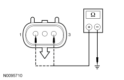 - Are the resistances greater than 10,000 ohms?
| Yes
GO to
Y11
.
No
REPAIR the affected circuit(s).
Refer to Wiring Diagrams Cell
5
, Connector Repair Procedures for schematic and connector information.
GO to
Y15
.
|
|
Y11 CHECK THE
OUTPUT
|
|
- Connect:
C3043.
- Ignition ON.
- Measure the voltage between
C3238-1, circuit LR142 (YE/BU), harness side and C3238-2, circuit GD138 (BK/WH), harness side.
- Is the voltage approximately 5 volts?
| Yes
GO to
Y12
.
No
INSTALL a new
sensor. REFER to
Occupant Classification Sensor
in this section. GO to
Y15
.
|
|
Y12 CHECK
VOLTAGE OUTPUT
|
|
- Ignition OFF.
- Depower the
. Refer to
Supplemental Restraint System (SRS) Depowering and Repowering
in this section.
- Disconnect: Passenger Seat Side Air Bag Module C337.
- Connect a fused jumper wire between
C3238-1, circuit LR142 (YE/BU), harness side and C3238 pin 1, component side.
- Connect a fused jumper wire between
C3238-2, circuit GD138 (BK/WH), harness side and C3238 pin 2, component side.
- Repower the
.
Do not
prove out the system at this time. Refer to
Supplemental Restraint System (SRS) Depowering and Repowering
in this section.
- Ignition ON.
- Measure the voltage between
C3238 pin 3, component side and ground as the tension of the
varies by pulling upward at the safety belt webbing.
- Does the voltage vary from approximately 0.95 volt with no tension applied to the sensor, to approximately 3.8 volts with full tension applied to the sensor?
| Yes
GO to
Y13
.
No
INSTALL a new safety belt retractor assembly. REFER to
Section 501-20A
. GO to
Y15
.
|
|
Y13 CONFIRM THE
FAULT
|
|
NOTE:
Make sure all
components, restraint system sensor electrical connectors and the
electrical connectors are connected before carrying out self-test. If not, DTCs will be recorded.
- Ignition OFF.
- Depower the
. Refer to
Supplemental Restraint System (SRS) Depowering and Repowering
in this section.
- Prior to reconnecting any previously disconnected
component:
- inspect connector(s) (including any in-line connectors) for pushed-out, loose or spread terminals and loose or frayed wire connections at terminals.
- inspect wire harness for any damage, pinched, cut or pierced wires.
- Connect: All Previously Disconnected Component(s)/Connector(s).
- Repower the
.
Do not
prove out the
at this time. Refer to
Supplemental Restraint System (SRS) Depowering and Repowering
in this section.
- Enter the following diagnostic mode on the scan tool: Self Test —
.
- Enter the following diagnostic mode on the scan tool: DataLogger —
— View and Record All 2909 Fault PIDs.
- Refer to PID list in Normal Operation to view 2909 fault PIDs.
- Does the original on-demand 2909 fault PID indicate a fault?
| Yes
INSTALL a new
sensor. REFER to
Occupant Classification Sensor
in this section. GO to
Y15
.
No
In the process of diagnosing the fault, the fault condition has become intermittent.
Do not install any new
components at this time.
components should only be installed when directed to do so in the pinpoint test.
GO to
Y14
.
|
|
Y14 CHECK FOR AN INTERMITTENT FAULT
|
|
- Ignition OFF.
- Disconnect
C3238:
- Connect: All Previously Disconnected Component(s)/Connector(s).
- Enter the following diagnostic mode on the scan tool: Self Test —
.
- Enter the following diagnostic mode on the scan tool: DataLogger —
— View and Record All 2909 Fault PIDs.
- Refer to PID list in Normal Operation to view 2909 fault PIDs.
- Do any on-demand 2909 fault PIDs indicate a fault?
| Yes
This is a hard fault. This fault cannot be cleared until it is corrected and the DTC is no longer retrieved on-demand during self-test.
Using the on-demand fault PIDs recorded, GO to the appropriate pinpoint test step.
For fault PID 2909_31_OD, GO to
Y2
.
For fault PID 2909_28_OD, GO to
Y8
.
For 2909_30_OD, GO to
Y9
.
For fault PID 2909_29_OD, GO to
Y10
.
No
CHECK for causes of the intermittent fault. ATTEMPT to recreate the hard fault by flexing the wire harness and cycling the ignition frequently. ACTIVATE other systems in the same wire harness.
Do not install any new
components at this time.
components should only be installed when directed to do so in the pinpoint test.
REPAIR any intermittent wiring, terminal or connector concerns found.
Refer to Wiring Diagrams Cell
5
, Connector Repair Procedures for schematic and connector information.
GO to
Y15
.
|
|
Y15 CHECK FOR ADDITIONAL
DTCs
|
|
- Ignition OFF.
- WARNING: Turn the ignition OFF and wait one minute to deplete the backup power supply. Failure to follow this instruction may result in serious personal injury or death in the event of an accidental deployment.
- Reconnect all
components (if previously disconnected).
- If previously directed to depower the
, repower the
.
Do not
prove out the
at this time. Refer to
Supplemental Restraint System (SRS) Depowering and Repowering
in this section.
- Ignition ON.
- Enter the following diagnostic mode on the scan tool: Self Test — Restraints.
- NOTE:
When selecting Restraints from the Self Test menu, DTCs will be retrieved from the
and
.
- Are any
and/or
DTCs retrieved?
| Yes
Do not clear any DTCs until all DTCs have been resolved. GO to the DTC Charts in this section for pinpoint test direction.
No
CLEAR all
and
. PROVE OUT the
. The repair is complete. RETURN the vehicle to the customer.
|