Printable / zoomable view of this graphic
SECTION 307-01: Automatic Transaxle/Transmission — 6R80
| 2014 Mustang Workshop Manual
|
DESCRIPTION AND OPERATION
| Procedure revision date: 01/07/2013
|
Transmission Operation Overview
Transmission operation is controlled by the PCM.
Torque Converter
This transmission uses a torque converter with the following elements:
For component information, refer to Torque Converter in this section.
Planetary Gearsets
Operation of this transmission involves the use of 2 planetary gearsets that have the following components:
Apply Clutches
This transmission uses the following clutches to operate the 2 planetary gearsets:
For information about planetary gearsets or the apply clutches, refer to Mechanical Components and Functions in this section.
Hydraulic System
The hydraulic operation of this transmission includes the following components:
For component information, refer to Hydraulic System in this section.
Electronic Operation
The PCM controls the operation of this transmission with the following solenoids:
For solenoid information, refer to Transmission Electronic Control System in this section.
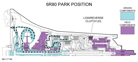
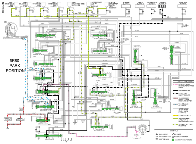
Park Position
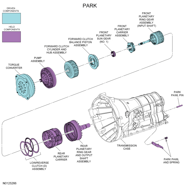
Apply components:
Front planetary gearset driving components:
Front planetary gearset driven components:
Front planetary gearset held components:
Rear planetary gearset driving components:
Rear planetary gearset driven components:
Rear planetary gearset held components:
Park Position Clutch Application Chart
| Gear | Forward A (1,2,3,4) | Direct B (3,5,R) | Inter-mediate C (2,6) | Low/ Reverse D (1,R) | Overdrive E (4,5,6) | Low-OWC |
|---|---|---|---|---|---|---|
| Park | H | |||||
| Planetary Components | Front planetary carrier-to-No. 3 sun gear | Front carrier-to-No. 2 sun gear | No. 2 sun gear | Rear planetary carrier | Input shaft-to-rear planetary carrier | Rear planetary carrier |
For component information, refer to Mechanical Components and Functions in this section.
Line pressure hydraulic circuits:
Torque converter circuits:
Cooler and lubrication hydraulic circuits:
Solenoid hydraulic circuits:
Clutch hydraulic circuits:
For hydraulic circuit information, refer to Hydraulic Circuits in this section.
Solenoid operation:
Park Position Solenoid Operation Chart
| Selector Lever Position | PCM Commanded Gear | Shift Solenoid | TCC NL | ||||
|---|---|---|---|---|---|---|---|
| SSA NL (1,2,3,4) | SSB NH (3,5,R) | SSC NL (CB 2,6) | SSD NH (CB L/R 4,5,6) | SSE NC | |||
| P | P | Off | On | Off | On | On | Off |
CB = Clutch brake
NC = Normally closed
NH = Normally high
NL = Normally low
For solenoid information, refer to Transmission Electronic Control System in this section.
Printable / zoomable view of this graphic
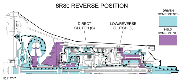
Reverse Position
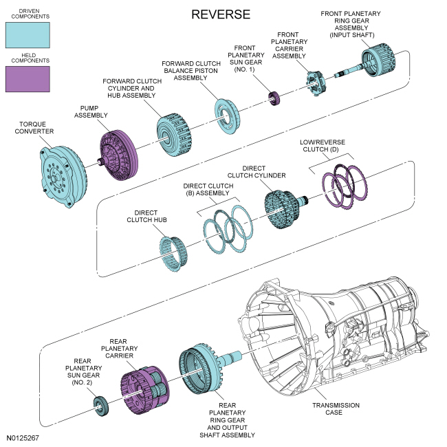
Apply components:
Front planetary gearset driving components:
Front planetary gearset driven components:
Front planetary gearset held components:
Rear planetary gearset driving components:
Rear planetary gearset driven components:
Rear planetary gearset held components:
Reverse Position Clutch Application Chart
| Gear | Forward A (1,2,3,4) | Direct B (3,5,R) | Inter-mediate C (2,6) | Low/ Reverse D (1,R) | Overdrive E (4,5,6) | Low-OWC |
|---|---|---|---|---|---|---|
| Reverse | D | H | ||||
| Planetary Components | Front planetary carrier-to-No. 3 sun gear | Front carrier-to-No. 2 sun gear | No. 2 sun gear | Rear planetary carrier | Input shaft-to-rear planetary carrier | Rear planetary carrier |
For component information, refer to Mechanical Components and Functions in this section.
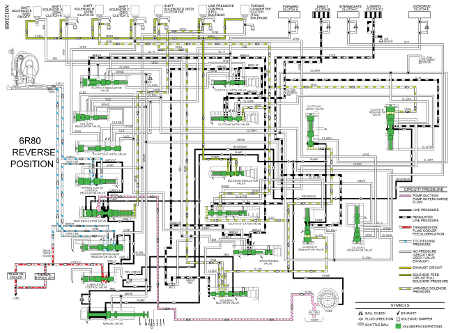
Line pressure hydraulic circuits:
Torque converter circuits:
Cooler and lubrication hydraulic circuits:
Solenoid hydraulic circuits:
Clutch hydraulic circuits:
For hydraulic circuit information, refer to Hydraulic Circuits in this section.
Solenoid operation:
Reverse Position Solenoid Operation Chart
| Selector Lever Position | PCM Commanded Gear | Shift Solenoid | TCC NL | ||||
|---|---|---|---|---|---|---|---|
| SSA NL (1,2,3,4) | SSB NH (3,5,R) | SSC NL (CB 2,6) | SSD NH (CB L/R 4,5,6) | SSE NC | |||
| R | R | Off | Off | Off | Off | On | Off |
CB = Clutch brake
NC = Normally closed
NH = Normally high
NL = Normally low
For solenoid information, refer to Transmission Electronic Control System in this section.
Printable / zoomable view of this graphic
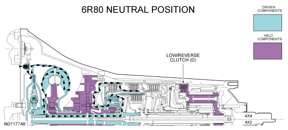
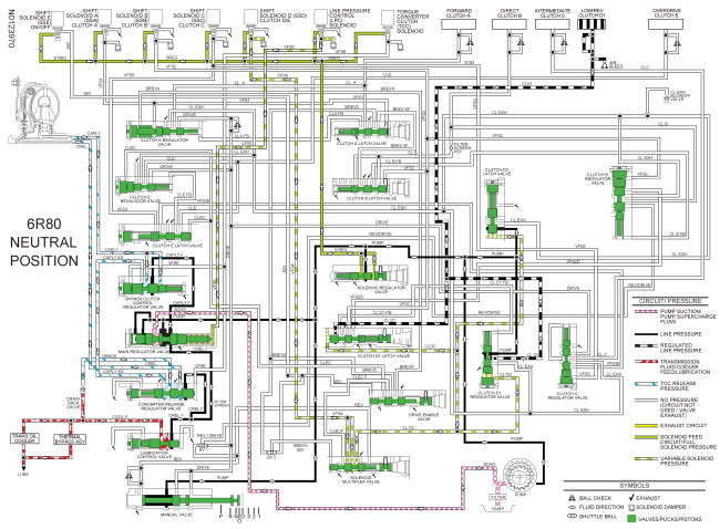
Neutral Position
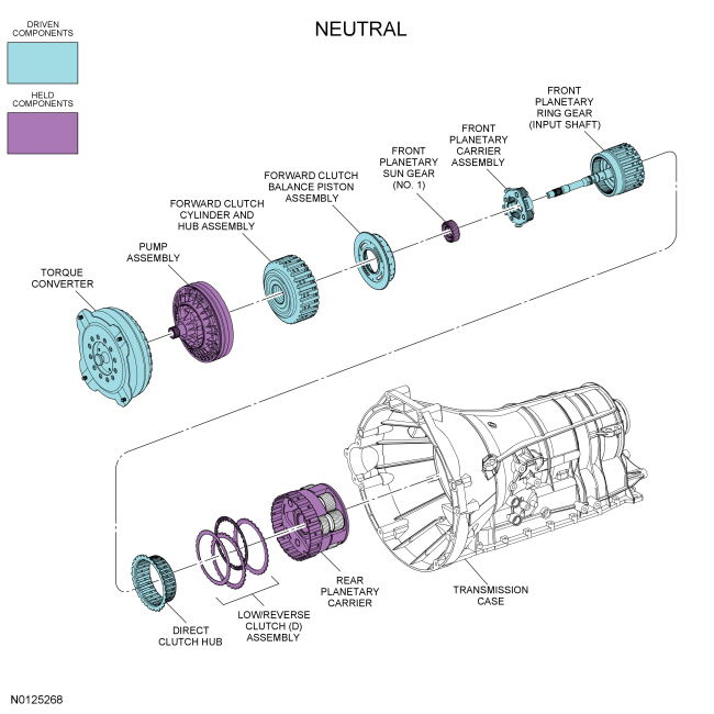
Apply components:
Front planetary gearset driving components:
Front planetary gearset driven components:
Front planetary gearset held components:
Rear planetary gearset driving components:
Rear planetary gearset driven components:
Rear planetary gearset held components:
Neutral Position Clutch Application Chart
| Gear | Forward A (1,2,3,4) | Direct B (3,5,R) | Inter-mediate C (2,6) | Low/ Reverse D (1,R) | Overdrive E (4,5,6) | Low-OWC |
|---|---|---|---|---|---|---|
| Neutral | H | |||||
| Planetary Components | Front planetary carrier-to-No. 3 sun gear | Front carrier-to-No. 2 sun gear | No. 2 sun gear | Rear planetary carrier | Input shaft-to-rear planetary carrier | Rear planetary carrier |
For component information, refer to Mechanical Components and Functions in this section.
Line pressure hydraulic circuits:
Torque converter circuits:
Cooler and lubrication hydraulic circuits:
Solenoid hydraulic circuits:
Clutch hydraulic circuits:
For hydraulic circuit information, refer to Hydraulic Circuits in this section.
Solenoid operation:
Neutral Position Solenoid Operation Chart
| Selector Lever Position | PCM Commanded Gear | Shift Solenoid | TCC NL | ||||
|---|---|---|---|---|---|---|---|
| SSA NL (1,2,3,4) | SSB NH (3,5,R) | SSC NL (CB 2,6) | SSD NH (CB L/R 4,5,6) | SSE NC | |||
| N | N | Off | On | Off | On a | On a | Off |
CB = Clutch brake
NC = Normally closed
NH = Normally high
NL = Normally low
For solenoid information, refer to Transmission Electronic Control System in this section.
Printable / zoomable view of this graphic
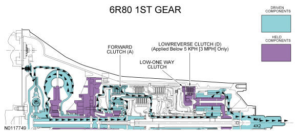
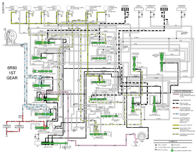
1st Gear
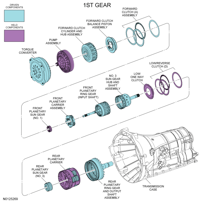
Apply components:
Front planetary gearset driving components:
Front planetary gearset driven components:
Front planetary gearset held components:
Rear planetary gearset driving components:
Rear planetary gearset driven components:
Rear planetary gearset held components:
1st Gear Clutch Application Chart
| Gear | Forward A (1,2,3,4) | Direct B (3,5,R) | Inter-mediate C (2,6) | Low/ Reverse D (1,R) | Overdrive E (4,5,6) | Low-OWC |
|---|---|---|---|---|---|---|
| 1st Gear D | D | H a | H | |||
| 1st Gear Manual | D | H | H | |||
| Planetary Components | Front planetary carrier-to-No. 3 sun gear | Front carrier-to-No. 2 sun gear | No. 2 sun gear | Rear planetary carrier | Input shaft-to-rear planetary carrier | Rear planetary carrier |
For component information, refer to Mechanical Components and Functions in this section.
Line pressure hydraulic circuits:
Torque converter circuits:
Cooler and lubrication hydraulic circuits:
Solenoid hydraulic circuits:
Clutch hydraulic circuits:
For hydraulic circuit information, refer to Hydraulic Circuits in this section.
Solenoid operation:
1st Gear Solenoid Operation Chart
| Selector Lever Position | PCM Commanded Gear | Shift Solenoid | TCC NL | ||||
|---|---|---|---|---|---|---|---|
| SSA NL (1,2,3,4) | SSB NH (3,5,R) | SSC NL (CB 2,6) | SSD NH (CB L/R 4,5,6) | SSE NC | |||
| D | 1 | On | On | Off | Off b | On | Off |
| 1 | 1 | On | On | Off | Off | On | Off |
CB = Clutch brake
NC = Normally closed
NH = Normally high
NL = Normally low
For solenoid information, refer to Transmission Electronic Control System in this section.
Printable / zoomable view of this graphic
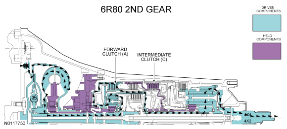
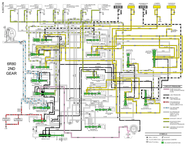
2nd Gear
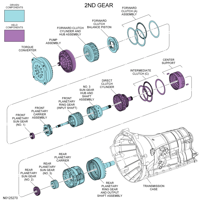
Apply components:
Front planetary gearset driving components:
Front planetary gearset driven components:
Front planetary gearset held components:
Rear planetary gearset driving components:
Rear planetary gearset driven components:
Rear planetary gearset held components:
2nd Gear Clutch Application Chart
| Gear | Forward A (1,2,3,4) | Direct B (3,5,R) | Inter-mediate C (2,6) | Low/ Reverse D (1,R) | Overdrive E (4,5,6) | Low-OWC |
|---|---|---|---|---|---|---|
| 2nd Gear D and Manual 2 | D | H | O/R | |||
| Planetary Components | Front planetary carrier-to-No. 3 sun gear | Front carrier-to-No. 2 sun gear | No. 2 sun gear | Rear planetary carrier | Input shaft-to-rear planetary carrier | Rear planetary carrier |
For component information, refer to Mechanical Components and Functions in this section.
Line pressure hydraulic circuits:
Torque converter circuits:
Cooler and lubrication hydraulic circuits:
Solenoid hydraulic circuits:
Clutch hydraulic circuits:
For hydraulic circuit information, refer to Hydraulic Circuits in this section.
Solenoid operation:
2nd Gear Solenoid Operation Chart
| Selector Lever Position | PCM Commanded Gear | Shift Solenoid | TCC NL | ||||
|---|---|---|---|---|---|---|---|
| SSA NL (1,2,3,4) | SSB NH (3,5,R) | SSC NL (CB 2,6) | SSD NH (CB L/R 4,5,6) | SSE NC | |||
| D and 2 | 2 | On | On | On | On | Off | Off |
CB = Clutch brake
NC = Normally closed
NH = Normally high
NL = Normally low
For solenoid information, refer to Transmission Electronic Control System in this section.
Printable / zoomable view of this graphic
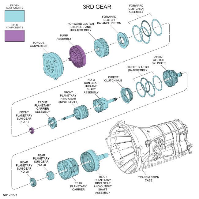
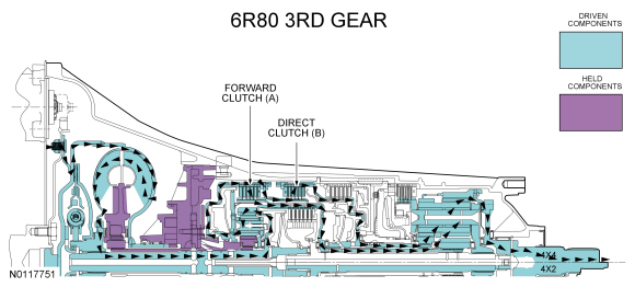
3rd Gear
Apply components:
Front planetary gearset driving components:
Front planetary gearset driven components:
Front planetary gearset held components:
Rear planetary gearset driving components:
Rear planetary gearset driven components:
Rear planetary gearset held components:
3rd Gear Clutch Application Chart
| Gear | Forward A (1,2,3,4) | Direct B (3,5,R) | Inter-mediate C (2,6) | Low/ Reverse D (1,R) | Overdrive E (4,5,6) | Low-OWC |
|---|---|---|---|---|---|---|
| 3rd Gear D and Manual 3 | D | D | O/R | |||
| Planetary Components | Front planetary carrier-to-No. 3 sun gear | Front carrier-to-No. 2 sun gear | No. 2 sun gear | Rear planetary carrier | Input shaft-to-rear planetary carrier | Rear planetary carrier |
For component information, refer to Mechanical Components and Functions in this section.
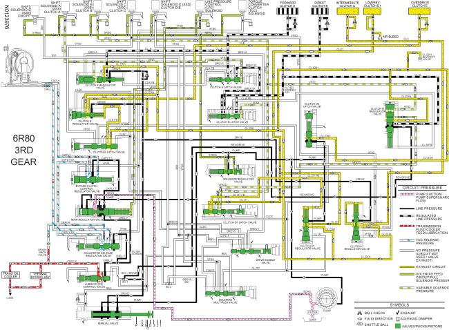
Line pressure hydraulic circuits:
Torque converter circuits:
Cooler and lubrication hydraulic circuits:
Solenoid hydraulic circuits:
Clutch hydraulic circuits:
For hydraulic circuit information, refer to Hydraulic Circuits in this section.
Solenoid operation:
3rd Gear Solenoid Operation Chart
| Selector Lever Position | PCM Commanded Gear | Shift Solenoid | TCC NL | ||||
|---|---|---|---|---|---|---|---|
| SSA NL (1,2,3,4) | SSB NH (3,5,R) | SSC NL (CB 2,6) | SSD NH (CB L/R 4,5,6) | SSE NC | |||
| D and 3 | 3 | On | Off | Off | On | Off | Off |
CB = Clutch brake
NC = Normally closed
NH = Normally high
NL = Normally low
For solenoid information, refer to Transmission Electronic Control System in this section.
Printable / zoomable view of this graphic
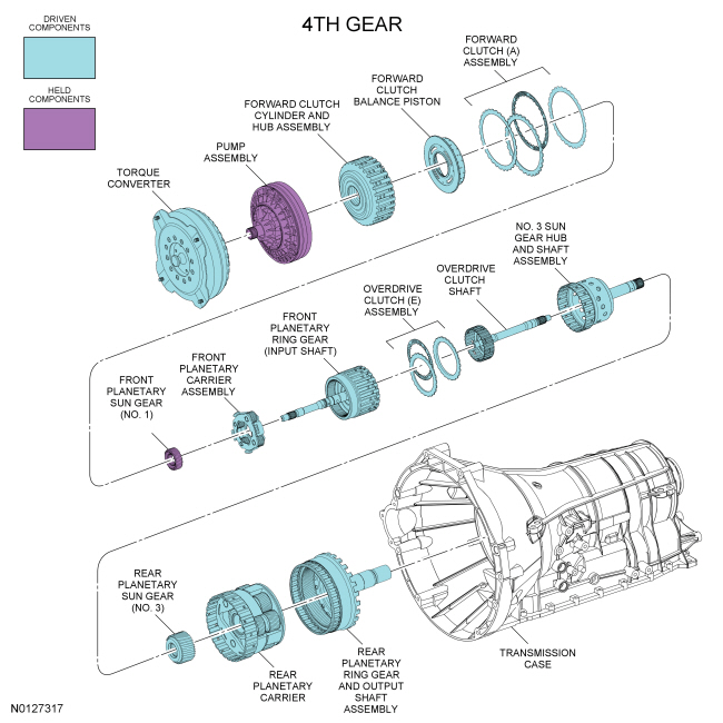
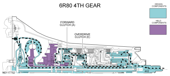
4th Gear
Apply components:
Front planetary gearset driving components:
Front planetary gearset driven components:
Front planetary gearset held components:
Rear planetary gearset driving components:
Rear planetary gearset driven components:
Rear planetary gearset held components:
4th Gear Clutch Application Chart
| Gear | Forward A (1,2,3,4) | Direct B (3,5,R) | Inter-mediate C (2,6) | Low/ Reverse D (1,R) | Overdrive E (4,5,6) | Low-OWC |
|---|---|---|---|---|---|---|
| 4th Gear D | D | D | O/R | |||
| Planetary Components | Front planetary carrier-to-No. 3 sun gear | Front carrier-to-No. 2 sun gear | No. 2 sun gear | Rear planetary carrier | Input shaft-to-rear planetary carrier | Rear planetary carrier |
For component information, refer to Mechanical Components and Functions in this section.
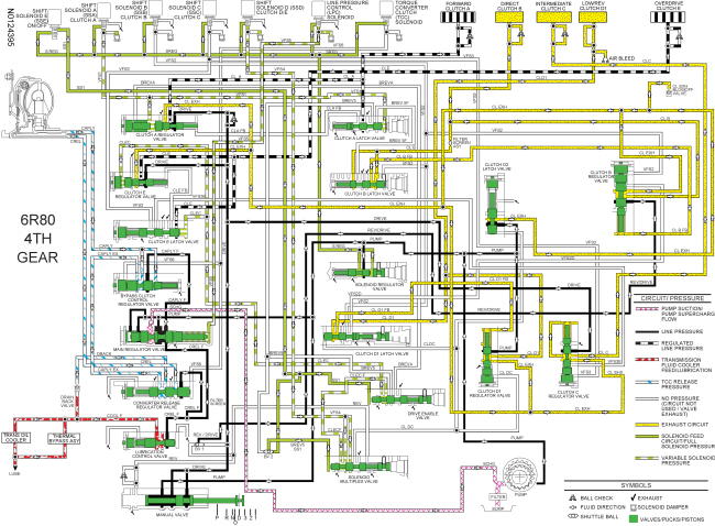
Line pressure hydraulic circuits:
Torque converter circuits:
Cooler and lubrication hydraulic circuits:
Solenoid hydraulic circuits:
Clutch hydraulic circuits:
For hydraulic circuit information, refer to Hydraulic Circuits in this section.
Solenoid operation:
4th Gear Solenoid Operation Chart
| Selector Lever Position | PCM Commanded Gear | Shift Solenoid | TCC NL | ||||
|---|---|---|---|---|---|---|---|
| SSA NL (1,2,3,4) | SSB NH (3,5,R) | SSC NL (CB 2,6) | SSD NH (CB L/R 4,5,6) | SSE NC | |||
| D | 4 | On | On | Off | Off | Off | On/Off |
CB = Clutch brake
NC = Normally closed
NH = Normally high
NL = Normally low
For solenoid information, refer to Transmission Electronic Control System in this section.
Printable / zoomable view of this graphic
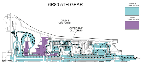
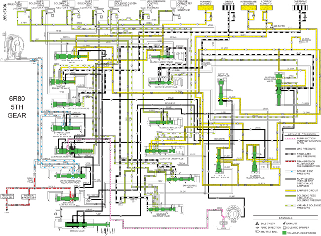
5th Gear
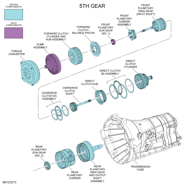
Apply components:
Front planetary gearset driving components:
Front planetary gearset driven components:
Front planetary gearset held components:
Rear planetary gearset driving components:
Rear planetary gearset driven components:
Rear planetary gearset held components:
5th Gear Clutch Application Chart
| Gear | Forward A (1,2,3,4) | Direct B (3,5,R) | Inter-mediate C (2,6) | Low/ Reverse D (1,R) | Overdrive E (4,5,6) | Low-OWC |
|---|---|---|---|---|---|---|
| 5th Gear D | D | D | O/R | |||
| Planetary Components | Front planetary carrier-to-No. 3 sun gear | Front carrier-to-No. 2 sun gear | No. 2 sun gear | Rear planetary carrier | Input shaft-to-rear planetary carrier | Rear planetary carrier |
For component information, refer to Mechanical Components and Functions in this section.
Line pressure hydraulic circuits:
Torque converter circuits:
Cooler and lubrication hydraulic circuits:
Solenoid hydraulic circuits:
Clutch hydraulic circuits:
For hydraulic circuit information, refer to Hydraulic Circuits in this section.
Solenoid operation:
5th Gear Solenoid Operation Chart
| Selector Lever Position | PCM Commanded Gear | Shift Solenoid | TCC NL | ||||
|---|---|---|---|---|---|---|---|
| SSA NL (1,2,3,4) | SSB NH (3,5,R) | SSC NL (CB 2,6) | SSD NH (CB L/R 4,5,6) | SSE NC | |||
| D | 5 | Off | Off | Off | Off | Off | On/Off |
CB = Clutch brake
NC = Normally closed
NH = Normally high
NL = Normally low
For solenoid information, refer to Transmission Electronic Control System in this section.
Printable / zoomable view of this graphic
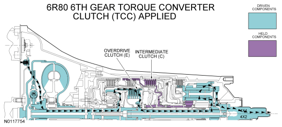
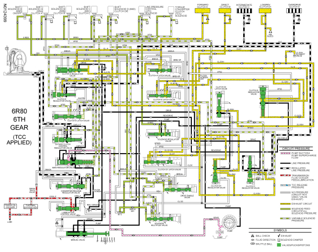
6th Gear Torque Converter Clutch (TCC) Applied
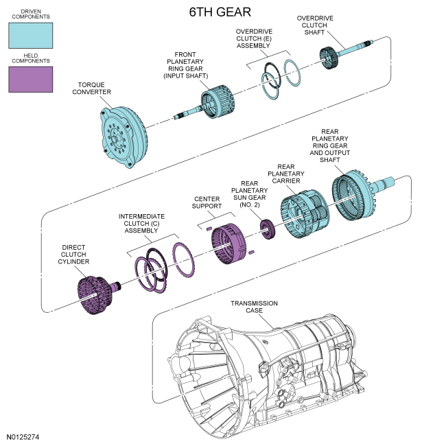
Apply components:
Front planetary gearset driving components:
Front planetary gearset driven components:
Front planetary gearset held components:
Rear planetary gearset driving components:
Rear planetary gearset driven components:
Rear planetary gearset held components:
6th Gear Torque Converter Clutch (TCC) Applied Clutch Application Chart
| Gear | Forward A (1,2,3,4) | Direct B (3,5,R) | Inter-mediate C (2,6) | Low/ Reverse D (1,R) | Overdrive E (4,5,6) | Low-OWC |
|---|---|---|---|---|---|---|
| 6th Gear D | H | D | O/R | |||
| Planetary Components | Front planetary carrier-to-No. 3 sun gear | Front carrier-to-No. 2 sun gear | No. 2 sun gear | Rear planetary carrier | Input shaft-to-rear planetary carrier | Rear planetary carrier |
For component information, refer to Mechanical Components and Functions in this section.
Line pressure hydraulic circuits:
Torque converter circuits:
Cooler and lubrication hydraulic circuits:
Solenoid hydraulic circuits:
Clutch hydraulic circuits:
For hydraulic circuit information, refer to Hydraulic Circuits in this section.
Solenoid operation:
6th Gear Torque Converter Clutch (TCC) Applied Solenoid Operation Chart
| Selector Lever Position | PCM Commanded Gear | Shift Solenoid | TCC NL | ||||
|---|---|---|---|---|---|---|---|
| SSA NL (1,2,3,4) | SSB NH (3,5,R) | SSC NL (CB 2,6) | SSD NH (CB L/R 4,5,6) | SSE NC | |||
| 6 | Off | On | On | Off | Off | On/Off | |
CB = Clutch brake
NC = Normally closed
NH = Normally high
NL = Normally low
For solenoid information, refer to Transmission Electronic Control System in this section.
Printable / zoomable view of this graphic
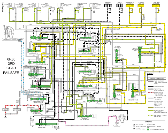
3rd Gear Fail Safe
Apply components:
Front planetary gearset driving components:
Front planetary gearset driven components:
Front planetary gearset held components:
Rear planetary gearset driving components:
Rear planetary gearset driven components:
Rear planetary gearset held components:
3rd Gear Fail Safe Clutch Application Chart
| Gear | Forward A (1,2,3,4) | Direct B (3,5,R) | Inter-mediate C (2,6) | Low/ Reverse D (1,R) | Overdrive E (4,5,6) | Low-OWC |
|---|---|---|---|---|---|---|
| 3rd Gear D and Manual 3 | D | D | O/R | |||
| Planetary Components | Front planetary carrier-to-No. 3 sun gear | Front carrier-to-No. 2 sun gear | No. 2 sun gear | Rear planetary carrier | Input shaft-to-rear planetary carrier | Rear planetary carrier |
For component information, refer to Mechanical Components and Functions in this section.
Line pressure hydraulic circuits:
Torque converter circuits:
Cooler and lubrication hydraulic circuits:
Solenoid hydraulic circuits:
Clutch hydraulic circuits:
For hydraulic circuit information, refer to Hydraulic Circuits in this section.
Solenoid operation: In failsafe, voltage is removed from all solenoids and the solenoids default to their normal position. If a solenoid is a normally low (NL) solenoid, the solenoid will not supply pressure to the regulator valve, releasing the clutch that it controls. If a solenoid is a normally high (NH) solenoid, the solenoid will provide high pressure to the regulator valve, applying the clutch that it controls.
3rd Gear Fail Safe Solenoid Operation Chart
| Gear | SSA NL (1,2,3,4) | SSB NH (3,5,R) | SSC NL (CB 2,6) | SSD NH (CB L/R 4,5,6) | SSE NC | LPC NH | TCC NL |
|---|---|---|---|---|---|---|---|
| 3rd Gear | — | — | — | — | — | — | — |
CB = Clutch brake
NC = Normally closed
NH = Normally high
NL = Normally low
For solenoid information, refer to Transmission Electronic Control System in this section.
Printable / zoomable view of this graphic