
FLU77-4 or equivalent


105-R025D or equivalent
SECTION 501-14: Handles, Locks, Latches and Entry Systems
| 2014 Mustang Workshop Manual
|
DIAGNOSIS AND TESTING
| Procedure revision date: 01/07/2013
|
| Fluke 77-IV Digital Multimeter
FLU77-4 or equivalent |
| Vehicle Communication Module (VCM) and Integrated Diagnostic System (IDS) software with appropriate hardware, or equivalent scan tool
|
| Flex Probe Kit
105-R025D or equivalent |
| Item | Specification |
|---|---|
| Multi-Purpose Grease
XG-4 and/or XL-5 | ESB-M1C93-B |
| Penetrating and Lock Lubricant (US); Penetrating Fluid (Canada)
XL-1 (US); CXC-51-A (Canada) | — |
Principles of Operation
NOTE: The Smart Junction Box (SJB) is also known as the Generic Electronic Module (GEM).
Power Door Locks
Regardless of the key position, the SJB is supplied voltage at all times. When the SJB receives a signal from the Remote Keyless Entry (RKE) transmitter, or the door lock control switches, the SJB supplies a ground signal to the appropriate lock or unlock relay. The ground signal closes the relay which supplies voltage to the door lock actuators. The door lock actuators then actuate to a lock or unlock position.
Luggage Compartment Lid Release
NOTE: When using the Integrated Keyhead Transmitter (IKT), 2 presses of the luggage compartment lid release button (within 3 seconds) are required to release the luggage compartment lid.
The luggage compartment lid release system is inhibited when the vehicle speed exceeds 8 km/h (5 mph). The luggage compartment lid latch releases the luggage compartment lid when the customer requests it be opened using either the IKT or the luggage compartment lid release switch. When the SJB receives a signal to release the luggage compartment lid, the SJB supplies voltage to the luggage compartment lid latch. The luggage compartment lid latch then actuates to release the luggage compartment lid.
Remote Keyless Entry (RKE)
The SJB interprets radio frequency signals from the RKE transmitters. The SJB requests the illuminated entry feature to turn the interior lamps on when an unlock command is received. If a lock command is received, the illuminated entry feature turns off.
The RKE transmitter supplies a signal to the SJB when any button is pressed. The SJB then supplies voltage to the appropriate door lock actuator(s) to lock or unlock the doors. The RKE transmitter can also be used to release the luggage compartment lid or activate the panic alarm.
Inspection and Verification
Visual Inspection Chart
| Mechanical | Electrical |
|---|---|
|
|
NOTE: Make sure to use the latest scan tool software release.
If the cause is not visually evident, connect the scan tool to the Data Link Connector (DLC).NOTE: The Vehicle Communication Module (VCM) LED prove-out confirms power and ground from the DLC are provided to the VCM .
If the scan tool does not communicate with the VCM :DTC Charts
Body Control Module B (BCM-B) DTC Chart
NOTE: This module utilizes a 5-character DTC followed by a 2-character failure-type code. The failure-type code provides information about specific fault conditions such as opens, or shorts to ground. Continuous memory DTCs have an additional 2-character DTC status code suffix to assist in determining DTC history.
| DTC | Description | Action |
|---|---|---|
| B1219:11 | Interior Boot/Trunk Release Switch: Circuit Short To Ground | GO to Pinpoint Test F . |
| B1284:12 | Trunk/Boot Open Activation Request Hardwire: Circuit Short To Battery | GO to Pinpoint Test F . |
| B1284:14 | Trunk/Boot Open Activation Request Hardwire: Circuit Short To Ground or Open | GO to Pinpoint Test F . |
| All other DTCs | — | REFER to the Diagnostic Trouble Code (DTC) Chart in Section 419-10 . |
Instrument Panel Cluster (IPC) DTC Chart
NOTE: This module utilizes a 5-character DTC followed by a 2-character failure-type code. The failure-type code provides information about specific fault conditions such as opens, or shorts to ground. Continuous memory DTCs have an additional 2-character DTC status code suffix to assist in determining DTC history.
| DTC | Description | Action |
|---|---|---|
| B1218:44 | Transmitter Identification Code: Data Memory Failure | The Smart Junction Box (SJB) limit of 4 integrated keys is reached. PROGRAM a maximum of 4 integrated keys. REFER to Integrated Keyhead Transmitter (IKT) key programming using diagnostic equipment in Section 419-01B . CLEAR the DTCs. REPEAT the self-test. |
| B1218:51 | Transmitter Identification Code: Not Programmed | GO to Pinpoint Test H . |
| B1218:81 | Transmitter Identification Code: Invalid Serial Data Received | GO to Pinpoint Test G . |
| All other DTCs | — | REFER to the Diagnostic Trouble Code (DTC) Chart in Section 419-10 . |
Smart Junction Box (SJB) DTC Chart
| DTC | Description | Action |
|---|---|---|
| B1138 | Memory Full | The Smart Junction Box (SJB) limit of 4 integrated keys is reached. PROGRAM a maximum of 4 integrated keys. REFER to Integrated Keyhead Transmitter (IKT) key programming using diagnostic equipment in Section 419-01B . CLEAR the DTCs. REPEAT the self-test. |
| B1139 | Invalid Transmitter Identification Code | GO to Pinpoint Test G . |
| B2276 | Less Than 2 Transmitters Programmed | PROGRAM all of the customer's Integrated Keyhead Transmitters (IKTs) (minimum of 2). REFER to Section 419-01B . TEST the system for normal operation. |
| B2425 | Remote Keyless Entry Out of Synchronization | GO to Pinpoint Test G . |
| B2667 | Liftglass Release Switch Circuit Failure | GO to Pinpoint Test F . |
| B2A25 | Trim Panel Lock Switch Circuit Failure | GO to Pinpoint Test E . |
| All other DTCs | — | REFER to the Diagnostic Trouble Code (DTC) Chart in Section 419-10 . |
Symptom Chart
| Condition | Possible Sources | Action |
|---|---|---|
|
|
|
|
|
|
|
|
|
|
| |
|
| |
|
| |
|
| |
|
| |
|
| |
|
| |
|
| |
|
| |
|
| |
|
| |
|
|
|
|
|
|
| Condition | Possible Sources | Action |
|---|---|---|
|
| |
|
| |
|
| |
|
| |
|
| |
|
|
|
|
| |
|
| |
|
|
|
|
|
|
|
| |
|
|
Pinpoint Tests
Pinpoint Test A: All Door Locks Are Inoperative
Refer to Wiring Diagrams Cell 110 , Power Door Locks for schematic and connector information.
The Smart Junction Box (SJB) supplies voltage to the lock all relay, the unlock driver door relay or unlock all relay based upon input from the door lock control switches or the Remote Keyless Entry (RKE) transmitter. Upon a lock request, the SJB supplies voltage on the all door lock circuit and ground on the driver and passenger door lock circuits. Upon an unlock request, the voltage and ground are reversed on the previously listed circuits. When the door lock and unlock relays are not energized they are connected to ground. A dedicated SJB ground circuit is provided only for the lock and unlock relays.
This pinpoint test is intended to diagnose the following:
NOTICE: Use the correct probe adapter(s) when making measurements. Failure to use the correct probe adapter(s) may damage the connector.
NOTE: Failure to disconnect the battery when instructed will result in false resistance readings. Refer to Section 414-01 .
| Test Step | Result / Action to Take |
|---|---|
| A1 VERIFY THE OPERATION OF BOTH DOOR LOCK CONTROL SWITCHES | |
| Yes
GO to A2 . No GO to Pinpoint Test D . |
| A2 VERIFY ALL DOOR LOCKS ARE INOPERATIVE | |
| Yes
VERIFY the SJB fuse 17 (20A) is OK. If OK, GO to A3 . If not OK, GO to A5 . No GO to Symptom Chart - Electrical . |
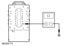
| A3 CHECK THE ALL LOCK CIRCUIT FOR AN OPEN | |
 | Yes
GO to A4 . No REPAIR circuit CPL11 (GY/BN) for an open. TEST the system for normal operation. |
| A4 CHECK THE POWER DOOR LOCK RELAY GROUND CIRCUIT FOR AN OPEN | |
 | Yes
GO to A8 . No REPAIR circuit GD133 (BK) for an open. TEST the system for normal operation. |
| A5 CHECK THE LUGGAGE COMPARTMENT LID RELEASE OUTPUT CIRCUIT FOR A SHORT TO GROUND | |
| Yes
GO to A7 . No GO to A6 . |
| A6 CHECK THE LUGGAGE COMPARTMENT LID RELEASE SOLENOID | |
| Yes
INSTALL a new luggage compartment lid latch. REFER to Luggage Compartment Lid Latch in this section. No REPAIR circuit CPL59 (BN/BU) for a short to ground. TEST the system for normal operation. |
| A7 CHECK THE ALL LOCK CIRCUIT FOR A SHORT TO GROUND | |
| Yes
REPAIR circuit CPL51 (BU/GN) or CPL52 (VT/GY) for a short to ground. TEST the system for normal operation. No REPAIR circuit CPL11 (GY/BN) for a short to ground. TEST the system for normal operation. |
| A8 CHECK FOR CORRECT SJB OPERATION | |
| Yes
INSTALL a new SJB . REFER to Section 419-10 . TEST the system for normal operation. No The system is operating correctly at this time. The concern may have been caused by a loose or corroded connector. |
Pinpoint Test B: A Single Door Lock is Inoperative
Refer to Wiring Diagrams Cell 110 , Power Door Locks for schematic and connector information.
The Smart Junction Box (SJB) supplies voltage to the lock all relay, the unlock driver door relay or unlock all relay based upon input from the door lock control switches or the Remote Keyless Entry (RKE) transmitter. Upon a lock request, the SJB supplies voltage on the all door lock circuit and ground on the driver and passenger door lock circuits. Upon an unlock request, the voltage and ground are reversed on the previously listed circuits. When the door lock and unlock relays are not energized they are connected to ground. A dedicated SJB ground circuit is provided only for the lock and unlock relays.
This pinpoint test is intended to diagnose the following:
NOTICE: Use the correct probe adapter(s) when making measurements. Failure to use the correct probe adapter(s) may damage the connector.
| Test Step | Result / Action to Take | |||||||||
|---|---|---|---|---|---|---|---|---|---|---|
| B1 CHECK THE DOOR LATCH FOR BINDING | ||||||||||
| Yes
GO to B3 . No GO to B2 . | |||||||||
| B2 CHECK THE LOCK ROD FOR BINDING | ||||||||||
| Yes
REPAIR as necessary. TEST the system for normal operation. No INSTALL a new door latch. REFER to Door Latch in this section. TEST the system for normal operation. | |||||||||
| B3 CHECK THE ALL LOCK CIRCUIT FOR VOLTAGE | ||||||||||
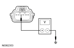 | Yes
GO to B4 . No REPAIR circuit CPL11 (GY/BN) for an open. TEST the system for normal operation. | |||||||||
| B4 CHECK THE UNLOCK CIRCUITS FOR VOLTAGE | ||||||||||
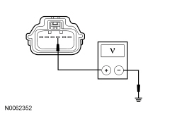 | Yes
INSTALL a new door latch for the door lock actuator in question. REFER to Door Latch in this section. TEST the system for normal operation. No GO to B5 . | |||||||||
| B5 CHECK THE UNLOCK CIRCUITS FOR AN OPEN | ||||||||||
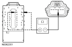 | Yes
GO to B6 . No REPAIR the circuit in question for an open. TEST the system for normal operation. | |||||||||
| B6 CHECK FOR CORRECT SJB OPERATION | ||||||||||
| Yes
INSTALL a new SJB . REFER to Section 419-10 . TEST the system for normal operation. No The system is operating correctly at this time. The concern may have been caused by a loose or corroded connector. |
Pinpoint Test C: The Door Locks Operate Only One Way
Refer to Wiring Diagrams Cell 110 , Power Door Locks for schematic and connector information.
The Smart Junction Box (SJB) sends voltage signals to both door lock control switches through the lock and unlock input circuits. When the lock or unlock switch is pressed, the corresponding voltage signal is routed to ground, signalling the SJB to lock or unlock the doors. The door lock control switches have a dedicated ground circuit.
This pinpoint test is intended to diagnose the following:
NOTICE: Use the correct probe adapter(s) when making measurements. Failure to use the correct probe adapter(s) may damage the connector.
| Test Step | Result / Action to Take |
|---|---|
| C1 CHECK THE RECORDED SJB DTCs FROM THE ON-DEMAND SELF-TEST | |
| Yes
GO to Pinpoint Test E . No GO to C2 . |
| C2 VERIFY THE OPERATION OF BOTH DOOR LOCK CONTROL SWITCHES | |
| Yes
GO to C4 . No GO to C3 . |
| C3 CHECK THE LOCK INPUT OR UNLOCK INPUT CIRCUIT FOR AN OPEN (SINGLE SWITCH INOPERATIVE) | |
  | Yes
INSTALL a new door lock control switch. REFER to Door Lock Control Switch in this section. TEST the system for normal operation. No REPAIR the input circuit in question for an open. TEST the system for normal operation. |
| C4 CHECK THE LOCK INPUT OR THE UNLOCK INPUT CIRCUIT FOR AN OPEN (BOTH SWITCHES INOPERATIVE) | |
  | Yes
GO to C5 . No REPAIR the circuit in question for an open. TEST the system for normal operation. |
| C5 CHECK FOR CORRECT SJB OPERATION | |
| Yes
INSTALL a new SJB . REFER to Section 419-10 . TEST the system for normal operation. No The system is operating correctly at this time. The concern may have been caused by a loose or corroded connector. |
Pinpoint Test D: All Door Locks Are Inoperative From One Switch
Refer to Wiring Diagrams Cell 110 , Power Door Locks for schematic and connector information.
The Smart Junction Box (SJB) sends voltage signals to both door lock control switches through the lock and unlock input circuits. When the lock or unlock switch is pressed, the corresponding voltage signal is routed to ground, signalling the SJB to lock or unlock the doors. The door lock control switches have a dedicated ground circuit.
This pinpoint test is intended to diagnose the following:
NOTICE: Use the correct probe adapter(s) when making measurements. Failure to use the correct probe adapter(s) may damage the connector.
| Test Step | Result / Action to Take |
|---|---|
| D1 CHECK THE DOOR LOCK CONTROL SWITCH | |
| Yes
REPAIR circuit GD133 (BK) or circuit GD139 (BK/YE) for an open. TEST the system for normal operation. No INSTALL a new door lock control switch. REFER to Door Lock Control Switch in this section. TEST the system for normal operation. |
Pinpoint Test E: DTC B2A25
Refer to Wiring Diagrams Cell 110 , Power Door Locks for schematic and connector information.
The Smart Junction Box (SJB) sends voltage signals to both door lock control switches through the lock and unlock input circuits. When the lock or unlock switch is pressed, the corresponding voltage signal is routed to ground, signalling the SJB to lock or unlock the doors. The door lock control switches have a dedicated ground circuit.
This pinpoint test is intended to diagnose the following:
NOTICE: Use the correct probe adapter(s) when making measurements. Failure to use the correct probe adapter(s) may damage the connector.
| Test Step | Result / Action to Take |
|---|---|
| E1 CHECK THE RECORDED SJB DTCs FROM THE ON-DEMAND SELF-TEST | |
| Yes
GO to E2 . No GO to Symptom Chart - Electrical . |
| E2 CHECK THE DRIVER DOOR LOCK CONTROL SWITCH | |
| Yes
LEAVE the switch disconnected. GO to E3 . No INSTALL a new driver door lock control switch. REFER to Door Lock Control Switch in this section. TEST the system for normal operation. |
| E3 CHECK THE PASSENGER DOOR LOCK CONTROL SWITCH | |
| Yes
LEAVE the switch disconnected. GO to E4 . No INSTALL a new passenger door lock control switch. REFER to Door Lock Control Switch in this section. TEST the system for normal operation. |
| E4 CHECK THE LOCK INPUT CIRCUIT OR THE UNLOCK INPUT CIRCUIT FOR A SHORT TO GROUND | |
 | Yes
GO to E5 . No REPAIR the circuit in question for a short to ground. CLEAR the DTCs. REPEAT the self-test. |
| E5 CHECK FOR CORRECT SJB OPERATION | |
| Yes
INSTALL a new SJB . REFER to Section 419-10 . TEST the system for normal operation. No The system is operating correctly at this time. The concern may have been caused by a loose or corroded connector. |
Pinpoint Test F: The Luggage Compartment Lid Release Is Inoperative/Does Not Operate Correctly
Refer to Wiring Diagrams Cell 113 , Luggage Compartment Lid Release for schematic and connector information.
When the Smart Junction Box (SJB) receives an open request from the luggage compartment lid switch or aRemote Keyless Entry (RKE) transmitter, the SJB supplies voltage to the luggage compartment lid latch. The luggage compartment lid latch has a dedicated ground circuit.
On coupe vehicles, the SJB sends a voltage signal to the luggage compartment lid release switch through the input circuit. When the luggage compartment lid release switch is pressed, the voltage signal is routed to ground, signalling the SJB to release the luggage compartment lid. The luggage compartment lid release switch has a dedicated ground circuit.
On convertible vehicles, the Body Control Module B (BCM-B) sends a voltage signal to the luggage compartment lid release switch through the input circuit. When the luggage compartment lid release switch is pressed, the voltage signal is routed to ground, signalling the BCM-B that there is a request to release the luggage compartment lid. The BCM-B monitors the inputs of ignition position, convertible top position, door lock request status, and the accessory power delay. Based upon the inputs, the BCM-B then supplies ground on the luggage compartment lid release input circuit to the SJB , and the luggage compartment lid releases.
The luggage compartment lid release switch inhibit feature disables the luggage compartment lid from releasing when activated by the luggage compartment lid release switch, when the convertible top is down and the vehicle has been electronically locked by a door lock control switch or a lock command from a Remote Keyless Entry (RKE) transmitter. The luggage compartment lid release switch is enabled when the vehicle is unlocked using a RKE transmitter or the ignition is turned to the ON position.
| DTC Description | Fault Trigger Conditions |
|---|---|
| An on-demand DTC that sets if the BCM-B detects a short to ground on the luggage compartment lid release switch input circuit. |
| A continuous and on-demand DTC that sets if the BCM-B detects a short to voltage on the luggage compartment lid release output circuit to the SJB . |
| A continuous and on-demand DTC that sets if the BCM-B detects a short to ground or open on the luggage compartment lid release output circuit to the SJB . |
| An on-demand DTC that sets if the SJB detects a short to ground on the luggage compartment lid release switch input circuit. This code will also set if the luggage compartment lid release switch is pressed for longer than 2 minutes. |
This pinpoint test is intended to diagnose the following:
NOTICE: Use the correct probe adapter(s) when making measurements. Failure to use the correct probe adapter(s) may damage the connector.
NOTE: Failure to disconnect the battery when instructed will result in false resistance readings. Refer to Section 414-01 .
| Test Step | Result / Action to Take |
|---|---|
| F1 CHECK THE DOOR LOCK OPERATION | |
| Yes
GO to F2 . No GO to Pinpoint Test A . |
| F2 CARRY OUT THE SJB LUGGAGE COMPARTMENT LID RELEASE ACTIVE COMMAND USING THE SCAN TOOL | |
| Yes
For coupe vehicles, GO to F8 . For convertible vehicles, GO to F11 . No GO to F3 . |
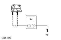
| F3 CHECK THE LATCH GROUND CIRCUIT FOR AN OPEN | |
 | Yes
GO to F4 . No REPAIR circuit GD110 (BK/WH) for an open. TEST the system for normal operation. |
| F4 CHECK FOR A SHORT TO VOLTAGE TO THE LUGGAGE COMPARTMENT LID LATCH | |
 | Yes
GO to F5 . No GO to F6 . |
| F5 CHECK THE LUGGAGE COMPARTMENT LID RELEASE CIRCUIT FOR A SHORT TO VOLTAGE | |
| Yes
REPAIR circuit CPL59 (BN/BU) for a short to voltage. TEST the system for normal operation. No GO to F18 . |
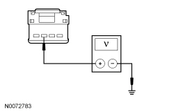
| F6 CHECK FOR VOLTAGE TO THE LUGGAGE COMPARTMENT LID LATCH | |
| Yes
INSTALL a new luggage compartment lid latch. REFER to Luggage Compartment Lid Latch in this section. TEST the system for normal operation. No GO to F7 . |
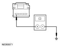
| F7 CHECK THE LUGGAGE COMPARTMENT LID RELEASE CIRCUIT FOR AN OPEN | |
 | Yes
GO to F18 . No REPAIR circuit CPL59 (BN/BU) for an open. TEST the system for normal operation. |
| F8 CHECK THE LUGGAGE COMPARTMENT LID RELEASE INPUT CIRCUIT | |
 | Yes
GO to F9 . No GO to F10 . |
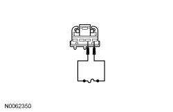
| F9 CHECK THE LUGGAGE COMPARTMENT LID RELEASE SWITCH | |
 | Yes
INSTALL a new luggage compartment lid release switch. TEST the system for normal operation. No REPAIR the ground circuit GD116 (BK/VT) for an open. TEST the system for normal operation. |
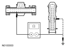
| F10 CHECK THE LUGGAGE COMPARTMENT LID RELEASE INPUT CIRCUIT FOR A SHORT TO GROUND AND OPEN | |
 | Yes
GO to F18 . No REPAIR the circuit. CLEAR the DTCs. REPEAT the self-test. TEST the system for normal operation. |
| F11 CHECK THE BCM-B LUGGAGE COMPARTMENT LID RELEASE PID | |
| Yes
GO to F12 . No GO to F14 . |
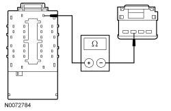
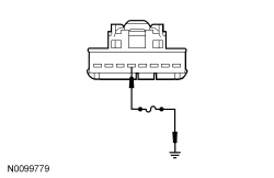
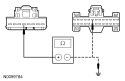
| F12 CHECK THE LUGGAGE COMPARTMENT LID RELEASE INPUT CIRCUIT TO THE SJB | |
NOTE: If the fuse in the jumper wire fails, repair circuit CPL79 (BN/VT) for a short to voltage.  | Yes
GO to F17 . No GO to F13 . |
| F13 CHECK THE LUGGAGE COMPARTMENT LID RELEASE INPUT CIRCUIT TO THE SJB FOR A SHORT TO GROUND AND OPEN | |
 | Yes
GO to F18 . No REPAIR the circuit. CLEAR the DTCs. REPEAT the self-test. TEST the system for normal operation. |
| F14 CHECK THE LUGGAGE COMPARTMENT LID RELEASE INPUT CIRCUIT TO THE BCM-B | |
| Yes
GO to F15 . No GO to F16 . |
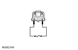
| F15 CHECK THE LUGGAGE COMPARTMENT LID RELEASE SWITCH | |
| Yes
INSTALL a new luggage compartment lid release switch. TEST the system for normal operation. No REPAIR the ground circuit GD116 (BK/VT) for an open. TEST the system for normal operation. |
| F16 CHECK THE LUGGAGE COMPARTMENT LID RELEASE INPUT CIRCUIT TO THE BCM-B FOR A SHORT TO GROUND AND OPEN | |
 | Yes
GO to F17 . No REPAIR the circuit. CLEAR the DTCs. REPEAT the self-test. TEST the system for normal operation. |
| F17 CHECK FOR CORRECT BCM-B OPERATION | |
| Yes
INSTALL a new BCM-B . REFER to Section 419-10 . TEST the system for normal operation. No The system is operating correctly at this time. The concern may have been caused by a loose or corroded connector. |
| F18 CHECK FOR CORRECT SJB OPERATION | |
| Yes
INSTALL a new SJB . REFER to Section 419-10 . TEST the system for normal operation. No The system is operating correctly at this time. The concern may have been caused by a loose or corroded connector. |
Pinpoint Test G: The Remote Keyless Entry (RKE) Transmitter Is Inoperative
Remote locking and unlocking of the doors, releasing the luggage compartment lid, and activating the panic alarm is accomplished by the Smart Junction Box (SJB) receiving a command message from the RKE Integrated Keyhead Transmitter (IKT). The IKTs and SJB also utilize a rolling code to prevent the code from being "captured" by a code grabber. The system advances the counter in the RKE transmitter and SJB every time an IKT button is pressed.
This pinpoint test is intended to diagnose the following:
NOTE: Aftermarket or dealer-installed systems may adversely affect the RKE system operation. These systems should be disconnected before diagnosing any RKE concerns.
| Test Step | Result / Action to Take |
|---|---|
| G1 CHECK FOR THE CORRECT RKE TRANSMITTERS | |
| Yes
GO to G2 . No The system cannot be tested without the correct IKTs . INFORM the customer that the correct IKTs must be present to proceed with diagnosis of the system. |
| G2 CHECK THE RECORDED SJB AND IPC DTCs FROM THE SELF-TEST | |
| Yes
For DTC B2425, GO to G3 . For DTC B1218:51, GO to Pinpoint Test H . No GO to G4 . |
| G3 RESYNCHRONIZE THE INOPERATIVE IKT | |
| Yes
The system is OK. CLEAR the DTCs. REPEAT the self-test. No GO to G4 . |
| G4 MAKE SURE THE RKE TRANSMITTER SIGNAL IS BEING RECEIVED | |
| Yes
GO to G5 . No GO to G6 . |
| G5 CHECK IF THE RKE TRANSMITTERS ARE PROGRAMMED | |
| Yes
GO to G8 . No PROGRAM the inoperative IKT individually or PROGRAM all the IKTs . REFER to Section 419-01B for the programming procedures. If all the IKTs are to be programmed, INFORM the customer that any IKTs not present need to be programmed. TEST the system for normal operation. |
| G6 CHECK THE IKT BATTERY | |
| Yes
GO to G7 . No INSTALL a new battery (make sure the battery is seated correctly). DO NOT reprogram the IKT (weak or dead batteries do not erase TICs from memory). TEST the system for normal operation. |
| G7 CHECK FOR NORMAL OPERATION WITH A KNOWN GOOD IKT | |
| Yes
REPLACE the inoperative IKT and PROGRAM the inoperative IKT individually or PROGRAM all the IKTs . REFER to Section 419-01B for the programming procedures. If all the IKTs are to be programmed, INFORM the customer that any IKTs not present need to be programmed. TEST the system for normal operation. No GO to G8 . |
| G8 CHECK FOR CORRECT SJB OPERATION | |
| Yes
INSTALL a new SJB . REFER to Section 419-10 . TEST the system for normal operation. No The system is operating correctly at this time. The concern may have been caused by a loose or corroded connector. |
Pinpoint Test H: DTC B1218:51
When an Integrated Keyhead Transmitter (IKT) key is programmed, the Remote Keyless Entry (RKE) Transmitter Identification Code (TIC) data from the key is received by the Instrument Panel Cluster (IPC). The IPC then sends the TIC data to the Smart Junction Box (SJB) over the Medium Speed Controller Area Network (MS-CAN). The SJB stores the TIC data in memory and sends an acknowledgement back to the IPC that the TIC data was successfully programmed.
This pinpoint test is intended to diagnose the following:
| Test Step | Result / Action to Take |
|---|---|
| H1 CHECK FOR THE CORRECT RKE TRANSMITTERS | |
| Yes
GO to H2 . No The system cannot be tested without the correct IKTs . INFORM the customer that the correct IKTs must be present to proceed with diagnosis of the system. |
| H2 CHECK FOR COMMUNICATION WITH THE IPC AND SJB | |
| Yes
REFER to Section 418-00 . No GO to H3 . |
| H3 REPROGRAM THE IKT KEYS | |
| Yes
GO to H5 . No GO to H4 . |
| H4 CHECK THE OPERATION OF THE RKE TRANSMITTER | |
| Yes
The system is operating normally. The concern may have been caused by an improperly programmed IKT key. No GO to Pinpoint Test G . |
| H5 CHECK FOR CORRECT SJB OPERATION | |
| Yes
INSTALL a new SJB . REFER to Section 419-10 . TEST the system for normal operation. No The system is operating correctly at this time. The concern may have been caused by a loose or corroded connector. |
Pinpoint Test I: An Individual Button/Feature Is Inoperative From The Remote Keyless Entry (RKE) Transmitter
When any Integrated Keyhead Transmitter (IKT) button is pressed, the Smart Junction Box (SJB) receives and processes the command to provide the appropriate output.
This pinpoint test is intended to diagnose the following:
NOTE: The panic feature will only operate when the key is in the OFF or LOCK positions.
| Test Step | Result / Action to Take |
|---|---|
| I1 VERIFY THE DOOR LOCK OPERATION | |
| Yes
GO to I2 . No GO to Symptom Chart - Electrical . |
| I2 VERIFY THE HORN OPERATION | |
| Yes
GO to I3 . No REFER to Section 413-06 . |
| I3 VERIFY THE HAZARD LAMP OPERATION | |
| Yes
GO to I4 . No REFER to Section 417-01 . |
| I4 VERIFY THE LUGGAGE COMPARTMENT LID RELEASE OPERATION | |
| Yes
REPLACE the inoperative IKT and PROGRAM the IKT individually or PROGRAM all the IKTs . REFER to Section 419-01B for the programming procedures. If all the IKTs are to be programmed, INFORM the customer that any IKTs not present need to be programmed. TEST the system for normal operation. No GO to Symptom Chart - Electrical . |
Pinpoint Test J: The Remote Keyless Entry (RKE) Transmitter Has Poor Range Performance
The Remote Keyless Entry (RKE) transmitter sends a radio signal to the Smart Junction Box (SJB) based on the user selected RKE transmitter button. The SJB then carries out the selected action.
This pinpoint test is intended to diagnose the following:
NOTE: All RKE transmitters must be present to begin diagnosis of the RKE system.
NOTE: Aftermarket or dealer-installed systems may adversely affect RKE system operation. These systems should be disconnected before diagnosing any RKE concerns.
| Test Step | Result / Action to Take |
|---|---|
| J1 CHECK FOR THE CORRECT RKE TRANSMITTERS | |
| Yes
GO to J2 . No The system cannot be tested without the correct IKTs . INFORM the customer that the correct IKTs must be present to proceed with diagnosis of the system. |
| J2 CHECK ALL THE RKE TRANSMITTERS FOR POOR RANGE PERFORMANCE | |
NOTE: The 10 m (33 ft) measurement of range is not the standard but is a guideline that clearly indicates a vehicle is experiencing normal range performance. | Yes
GO to J4 . No GO to J3 . |
| J3 CHECK THE IKT BATTERY | |
| Yes
REPLACE the inoperative IKT and PROGRAM the IKT individually or PROGRAM all the IKTs . REFER to Section 419-01B for the programming procedures. If all the IKTs are to be programmed, INFORM the customer that any IKTs not present need to be programmed. TEST the system for normal operation. No INSTALL a new battery (make sure the battery is seated correctly). DO NOT reprogram the IKT (weak or dead batteries do not erase Transmitter Identification Codes (TICs) from memory). TEST the system for normal operation. |
| J4 CHECK THE LOCATION OF THE VEHICLE AND THE APPROACH ANGLES AROUND THE VEHICLE | |
| Yes
GO to J5 . No The system is operating correctly at this time. TEST the system for normal operation. |
| J5 CHECK FOR CORRECT SJB OPERATION | |
| Yes
INSTALL a new SJB . REFER to Section 419-10 . TEST the system for normal operation. No The system is operating correctly at this time. The concern may have been caused by a loose or corroded connector. |
Pinpoint Test K: The Autolock Does Not Operate Correctly
Refer to Wiring Diagrams Cell 117 , Remote Keyless Entry and Alarm for schematic and connector information.
The Smart Junction Box (SJB) energizes the lock relay based on input from the ajar switches, the ignition switch, the Transmission Range (TR) sensor and the vehicle speed signal. The SJB locks the doors when the following conditions are met:
This pinpoint test is intended to diagnose the following:
| Test Step | Result / Action to Take |
|---|---|
| K1 VERIFY THE AUTOLOCK FEATURE IS ENABLED | |
| Yes
GO to K2 . No PROGRAM the autolock feature. REFER to Autolock and Auto-Unlock Programming in this section. |
| K2 CHECK THE COURTESY LAMP OPERATION | |
| Yes
GO to K3 . No REFER to Section 417-02 . |
| K3 CHECK THE SJB PID (IGN_R_ECU) | |
| Yes
GO to K4 . No REFER to Section 211-05 . |
| K4 RETRIEVE THE RECORDED SJB DTCs FROM THE SELF-TEST | |
| Yes
REFER to Section 419-10 , Diagnosis and Testing, Smart Junction Box (SJB). No GO to K5 . |
| K5 CHECK FOR CORRECT SJB OPERATION | |
| Yes
INSTALL a new SJB . REFER to Section 419-10 . TEST the system for normal operation No The system is operating correctly at this time. The concern may have been caused by a loose or corroded connector. |
Pinpoint Test L: The Smart Unlock Does Not Operate Correctly
The Smart Junction Box (SJB) automatically unlocks all the doors after the doors are locked with a door lock control switch and the key is in the ignition lock cylinder and one of the doors is ajar. This feature helps prevent the keys from being locked in the vehicle by unlocking the doors if the key is in the ignition and either door is ajar.
The vehicle can still be locked with the key in the ignition, by using the manual lock rod, a key in the door lock cylinder, or the LOCK button on a Remote Keyless Entry (RKE) transmitter.
This pinpoint test is intended to diagnose the following:
| Test Step | Result / Action to Take |
|---|---|
| L1 CHECK THE DOOR LOCK OPERATION | |
| Yes
GO to L2 . No GO to Symptom Chart - Electrical . |
| L2 CHECK THE COURTESY LAMP OPERATION | |
| Yes
GO to L3 . No REFER to Section 417-02 . |
| L3 CHECK THE KEY-IN-IGNITION CHIME | |
| Yes
GO to L4 . No REFER to Section 413-01 . |
| L4 CHECK FOR CORRECT SJB OPERATION | |
| Yes
INSTALL a new SJB . REFER to Section 419-10 . TEST the system for normal operation. No The system is operating correctly at this time. The concern may have been caused by a loose or corroded connector. |
Pinpoint Test M: The Auto-Unlock Does Not Operate Correctly
The Smart Junction Box (SJB) energizes the unlock relay based upon input from the ajar switches and the vehicle speed signal. The SJB unlocks the doors when the following conditions are met:
This pinpoint test is intended to diagnose the following:
| Test Step | Result / Action to Take |
|---|---|
| M1 CHECK THE AUTO-UNLOCK CONFIGURATION | |
| Yes
GO to M2 . No ENABLE the auto-unlock. REFER to Autolock and Auto-Unlock Programming in this section. TEST the system for normal operation. |
| M2 CHECK THE COURTESY LAMP OPERATION | |
| Yes
GO to M3 . No REFER to Section 417-02 . |
| M3 CHECK THE SJB IGNITION STATUS PID | |
| Yes
GO to M4 . No REFER to Section 211-05 to continue diagnosis of the ignition switch. |
| M4 CHECK THE VEHICLE SPEED OPERATION | |
| Yes
GO to M5 . No REFER to Section 413-01 . |
| M5 CHECK FOR CORRECT SJB OPERATION | |
| Yes
INSTALL a new SJB . REFER to Section 419-10 . TEST the system for normal operation. No The system is operating correctly at this time. The concern may have been caused by a loose or corroded connector. |
Pinpoint Test N: Hard To Open/Close Door From Either Door Handle
The door latch can be actuated from the interior or exterior door handle. When actuated, the door latch releases and allows the door to open. If the door latch or the door hinges have insufficient lubrication or if the striker or door are misaligned, it causes extra force to be used when opening or closing the door.
This pinpoint test is intended to diagnose the following:
| Test Step | Result / Action to Take |
|---|---|
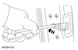
| N1 CHECK THE LATCH OPERATION FROM BOTH DOOR HANDLES | |
| Yes
If the door is difficult/does not open from the exterior door handle, GO to Pinpoint Test O . If the door is difficult/does not open from the interior door handle, GO to Pinpoint Test P . No If the door does not operate correctly from both door handles, GO to N2 . |
| N2 CHECK THE LATCH OPERATION | |
 | Yes
GO to N4 . No GO to N3 . |
| N3 CHECK THE LATCH OPERATION AFTER LUBRICATION | |
| Yes
The concern was caused by an insufficiently lubricated door latch. No INSTALL a new door latch. REFER to Door Latch in this section. TEST the system for normal operation. |
| N4 CHECK THE STRIKER ADJUSTMENT | |
| Yes
GO to N5 . No ADJUST the striker as necessary. TEST the system for normal operation. |
| N5 CHECK THE DOOR ALIGNMENT | |
| Yes
LUBRICATE the door hinges. TEST the system for normal operation. No ADJUST the door as necessary. TEST the system for normal operation. |
Pinpoint Test O: A Door Is Difficult/Does Not Open From The Exterior Door Handle
The exterior door handle is connected to the door latch with an actuating rod. When the exterior door handle is pulled it causes the actuating rod to push down on the latch lever. The actuating rod can be adjusted for proper exterior door handle operation. When the latch lever is moved, the door latch releases, allowing the door to open.
This pinpoint test is intended to diagnose the following:
| Test Step | Result / Action to Take |
|---|---|
| O1 CHECK THE LATCH OPERATION FROM BOTH DOOR HANDLES | |
| Yes
If the door is difficult/does not open from only the exterior door handle, GO to O2 . No If the door does not operate correctly from both door handles, GO to Pinpoint Test N . |
| O2 CHECK THE EXTERIOR DOOR HANDLE | |
 | Yes
GO to O3 . No INSTALL a new exterior door handle. REFER to Exterior Door Handle in this section. TEST the system for normal operation. |
| O3 CHECK THE EXTERIOR DOOR HANDLE AND LINKAGE OPERATION | |
| Yes
REPAIR as necessary. TEST the system for normal operation. No GO to O4 . |
| O4 CARRY OUT THE EXTERIOR DOOR HANDLE ADJUSTMENT | |
| Yes
The concern was caused by an improperly adjusted exterior door handle. No INSTALL a new door latch. REFER to Door Latch in this section. TEST the system for normal operation. |
Pinpoint Test P: A Door Is Difficult/Does Not Open From The Interior Door Handle
The interior door handle is connected to the door latch by an actuating cable. When the interior door handle is pulled it causes the cable to pull on the latch lever. When the latch lever is moved, the door latch releases, allowing the door to open.
This pinpoint test is intended to diagnose the following:
| Test Step | Result / Action to Take |
|---|---|
| P1 CHECK THE LATCH OPERATION FROM BOTH DOOR HANDLES | |
| Yes
If the door is difficult/does not open from only the interior door handle, GO to P2 . No If the door does not operate correctly from both door handles, GO to Pinpoint Test N . |
| P2 CHECK THE INTERIOR DOOR HANDLE AND CABLE/LINKAGE OPERATION | |
| Yes
REPAIR as necessary. TEST the system for normal operation. No INSTALL a new door latch. REFER to Door Latch in this section. TEST the system for normal operation. |
Pinpoint Test Q: Exterior Door Release Handle Sticks
The exterior door handle is connected to the door latch with an actuating rod. When the exterior door handle is pulled it causes the actuating rod to push down on the latch lever. The actuating rod can be adjusted for proper exterior door handle operation. When the latch lever is moved, the door latch releases, allowing the door to open. The handle has a return spring to make sure the handle returns to a closed position.
This pinpoint test is intended to diagnose the following:
| Test Step | Result / Action to Take |
|---|---|
| Q1 CHECK FOR A BROKEN RETURN SPRING | |
| Yes
GO to Q2 . No INSTALL a new exterior door handle. REFER to Exterior Door Handle in this section. TEST the system for normal operation. |
| Q2 CARRY OUT THE EXTERIOR DOOR HANDLE ADJUSTMENT | |
| Yes
The concern was caused by an improperly adjusted exterior door handle. No GO to Q3 . |
| Q3 CHECK THE EXTERIOR DOOR HANDLE AND LINKAGE OPERATION | |
| Yes
REPAIR as necessary. TEST the system for normal operation. No INSTALL a new door latch. REFER to Door Latch in this section. TEST the system for normal operation. |
Pinpoint Test R: Interior Door Release Handle Sticks
The interior door handle is connected to the door latch by an actuating cable. When the interior door handle is pulled it causes the cable to pull on the latch lever. When the latch lever is moved, the door latch releases, allowing the door to open. The handle has a return spring to make sure the handle returns to a closed position.
This pinpoint test is intended to diagnose the following:
| Test Step | Result / Action to Take |
|---|---|
| R1 CHECK FOR A BROKEN RETURN SPRING | |
| Yes
GO to R2 . No INSTALL a new interior door handle. REFER to Interior Door Handle in this section. TEST the system for normal operation. |
| R2 CHECK THE INTERIOR DOOR HANDLE CABLE OPERATION | |
| Yes
INSTALL a new door latch. REFER to Door Latch in this section. TEST the system for normal operation. No REPAIR as necessary. TEST the system for normal operation. |
Pinpoint Test S: Squeak/Rattle/Chucking Noise From Door
This pinpoint test is intended to diagnose the following:
| Test Step | Result / Action to Take |
|---|---|
| S1 CHECK FOR ANY LOOSE COMPONENTS | |
| Yes
REPAIR as necessary. TEST the system for normal operation. No GO to S2 . |
| S2 CHECK THE STRIKER ADJUSTMENT | |
| Yes
GO to S3 . No ADJUST the striker as necessary. TEST the system for normal operation. |
| S3 CHECK THE DOOR ALIGNMENT | |
| Yes
GO to S4 . No ADJUST the door as necessary. TEST the system for normal operation. |
| S4 CHECK THE LATCH OPERATION AFTER LUBRICATION | |
| Yes
INSTALL a new door latch. REFER to Door Latch in this section. TEST the system for normal operation. No The concern was caused by an insufficiently lubricated door latch. |
Pinpoint Test T: Manual Door Lock Cylinder Inoperative
The door lock cylinder is connected to the door latch via a lock rod and can be used to manually lock/unlock a door.
This pinpoint test is intended to diagnose the following:
| Test Step | Result / Action to Take |
|---|---|
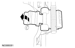
| T1 CHECK THE LOCK CYLINDER OPERATION AFTER LUBRICATION | |
| Yes
The concern was caused by an insufficiently lubricated lock cylinder. SPRAY a multi-purpose grease such as Motorcraft XL-5 into the lock cylinder for a couple seconds to provide long term lubrication. No GO to T2 . |
| T2 CHECK THE DOOR LOCK CYLINDER | |
| Yes
GO to T3 . No INSTALL a new door lock cylinder. REFER to Door Lock Cylinder in this section. TEST the system for normal operation. |
| T3 CHECK THE DOOR LOCK CYLINDER LINKAGE | |
| Yes
REPAIR as necessary. TEST the system for normal operation. No INSTALL a new door latch. REFER to Door Latch in this section. TEST the system for normal operation. |
Pinpoint Test U: Ignition Lock Cylinder Difficult To Turn
Diagnostics in this manual assume a certain skill level and knowledge of Ford-specific diagnostic practices. Refer to Diagnostic Methods in Section 100-00 for information about these practices.
The ignition lock cylinder mechanically rotates the ignition switch within the ignition lock cylinder housing. Insertion and extraction of the key and rotation of the lock cylinder using a correctly cut key should be smooth and require minimal effort.
| Test Step | Result / Action to Take |
|---|---|
| U1 CHECK THE KEY | |
| Yes
GO to U2 . No REPLACE and PROGRAM the key. REFER to Key Programming in Section 419-01B . |
| U2 CHECK THE IGNITION LOCK CYLINDER OPERATION | |
| Yes
The mechanical function of the ignition lock cylinder is OK. No GO to U3 . |
| U3 CHECK THE IGNITION LOCK CYLINDER WHILE INSERTING THE KEY | |
  | Yes
GO to U6 . No GO to U4 . |
| U4 CHECK THE KEY FOR BURRS | |
| Yes
GO to U5 . No REMOVE the burrs from the key and RECHECK the key operation. If the concern is still present, GO to U5 . |
| U5 CHECK THE IGNITION LOCKL CYLINDER USING ANOTHER KEY | |
| Yes
REPLACE the original key and PROGRAM the new key. REFER to Key Programming in Section 419-01B . No INSTALL a new ignition lock cylinder. REFER to Ignition Lock Cylinder . |
| U6 CHECK THE IGNITION LOCK CYLINDER FOR BINDING ROTATION | |
 | Yes
GO to U7 . No INSTALL a new ignition lock cylinder. REFER to Ignition Lock Cylinder . |
| U7 CHECK FOR BINDING WITHIN THE STEERING COLUMN LOCK MODULE | |
| Yes
INSTALL a new ignition switch. REFER to Section 211-05 . No INSTALL a new stering column lock module. Section 211-05 . |