
FLU77-4 or equivalent


NUD105-R025D or equivalent

105-00120
CCMUSB2-AM-AM-10
SECTION 415-00: Information and Entertainment Systems
| 2014 Mustang Workshop Manual
|
DIAGNOSIS AND TESTING
| Procedure revision date: 07/31/2013
|
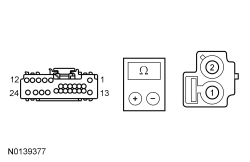
| Fluke 77-IV Digital Multimeter
FLU77-4 or equivalent |
| Vehicle Communication Module (VCM) and Integrated Diagnostic System (IDS) software with appropriate hardware, or equivalent diagnostic scan tool
|
| Flex Probe Kit
NUD105-R025D or equivalent |
| Multi-Media Interface Tester
105-00120 |
| Universal Serial Bus (USB) Male-A To Male-A Cable
CCMUSB2-AM-AM-10 |
Principles of Operation
AM/FM Antenna
The AM/FM antenna is a fixed mast antenna mounted on the exterior of the vehicle. The antenna receives both AM and FM radio waves. The audio signals are then sent to the ACM through the antenna cables.
Audio DSP Amplifier
The 8 channel non-networked audio DSP amplifier is found on Shaker/Shaker Pro-equipped vehicles. Audio signals are sent from the ACM to the audio DSP amplifier. These signals are amplified and sent to the 8-inch (203 mm) subwoofer speaker in each door , the 2 speaker assembly found in each door, and the 2 rear package tray (coupe) or 2 quarter panel (convertible) speakers.
Audio Front Control Module (ACM)
The Audio Front Control Module (ACM) operates with the ignition in RUN or ACC. The accessory delay feature allows the audio system to be operated for a preset period of time after the key is turned off and a door has not been opened. The ACM sends AC voltage audio signals to the speakers or to the amplifiers, depending on vehicle configuration. The ACM produces its own DTCs, which are communicated to the diagnostic scan tool through the Medium Speed Controller Area Network (MS-CAN). The enable/clip circuit is used to turn on the audio DSP amplifier or subwoofer amplifier, depending on vehicle configuration, and to monitor an overload condition of the amplifiers. In the event of an overload, the ACM clips the audio output signal to the amplifier (heard as distortion).
Audio Input Jack
The audio input jack allows for a portable MP3 player to be connected to the vehicle audio system. When a portable MP3 player is connected, audio from the MP3 player can be played through the vehicle speakers.
Audio Signals
Stereo signals contain left and right channel information, and are used for most audio signals.
A mono signal is used for the microphone input to the APIM . The mono signal is also used for the voice prompts, the TTS feature, ringtones, and any audio received through a connected mobile phone. These audio signals are output from the APIM to the ACM . The mono and stereo outputs from the APIM utilize separate circuits.
A digital signal is used to transmit data from a media device connected through the USB port to the APIM . The APIM then converts the signal to analog and relays the signal to the ACM .
A wireless signal is used to broadcast audio signals from a Bluetooth device to the APIM . As with a digital signal sent through the USB port, the APIM converts the wireless audio signal to analog and relays it to the ACM .
Front Controls Interface Module (FCIM)
The Front Controls Interface Module (FCIM) acts as a customer interface with the audio system and the climate control system. When a switch is pressed, a message is broadcast over the MS-CAN . When a climate control switch is pressed, the HVAC module sends a message back to the FCIM to illuminate the correct switches to indicate the status of the climate control.
Front Display Interface Module (FDIM) (Without Navigation)
The Front Display Interface Module (FDIM) receives MS-CAN messages for all of its displays, which include:
Front Display Interface Module (FDIM) (With Navigation)
The FDIM does not communicate on the CAN and is hardwired to the ACM . When the touchscreen is pressed, a signal is sent to the ACM , which acts on the signal by changing either the audio setting or by broadcasting a message via the MS-CAN to the module controlling the function that was selected. The audio system, navigation, and climate control video feed to the FDIM is provided by the ACM . If equipped with a rear view camera, the video feed for the camera is provided directly by the rear view camera.
GPS Antenna
The GPS antenna is integral to the satellite radio antenna and is only present on vehicles with navigation. The location signals are sent to the ACM via a coaxial cable. A GPS / SDARS antenna splitter is used to provide separate satellite radio and Global Positioning System (GPS) inputs to the ACM .
Global Positioning System Module (GPSM)
The Global Positioning System Module (GPSM) provides vehicle location for real-time traffic reports and re-routing, and for identifying vehicle location in the event of a collision. The vehicle location information is broadcast to the APIM over the MS-CAN . The GPSM is only present on vehicles with SYNC® and without navigation.
Jukebox Feature (With Navigation)
The ACM contains a 10 gigabyte on-board hard-drive that is capable of storing music from a CD. Music can be loaded into the ACM jukebox by inserting a non-MP3 CD, and following the on-screen instructions. If the ACM is replaced, the music contained on the hard-drive cannot be retained. For more information about the Jukebox feature, REFER to the Owner's Literature.
Luggage Compartment Subwoofer Amplifier
The 4 channel non-networked luggage compartment subwoofer amplifier is found on Shaker Pro-equipped vehicles. Audio signals are sent from the ACM to the luggage compartment subwoofer amplifier. These signals are amplified and sent to the 10-inch (254 mm) luggage compartment subwoofer enclosure. Only 2 of the 4 channels are utilized, and are bridged for higher power output to the subwoofer.
Navigation System
The vehicle navigation system guides the user to a pre-entered destination. No navigation map DVD is needed, as the map guidance information is stored in the ACM hard-drive. The ACM calculates route information based on GPS data. The ACM also uses vehicle speed and transmission gear selected signals received through the MS-CAN to detect vehicle speed and direction, resulting in more accurate navigation tracking.
The navigation display is shown on the FDIM . Either the FDIM touchscreen or the buttons on the FCIM can be used to interact with the navigation system.
The compass heading is derived from the GPS antenna signal. There are no serviceable parts for the compass.
A voice recognition system allows the user to interface with the system without using the touchscreen. A microphone contained in the overhead console provides the voice recognition input and is shared with the SYNC® system.
Noise Suppression Equipment
The radio frequency suppression equipment reduces interference transmitted through the speakers by the engine ignition and electrical systems. When installing any new radio suppression equipment components, make sure that a good contact is made at all connections.
Satellite Radio Antenna
The satellite radio antenna receives satellite radio signals. The signals are sent to the ACM through the satellite radio antenna cables. If equipped with the navigation system, an antenna splitter is used to provide separate satellite radio and Global Positioning System (GPS) inputs to the ACM .
Steering Wheel Switches
The steering wheel switches consist of a series of resistors. Each steering wheel switch function corresponds with a specific resistance value within the switch. When a switch is pressed, the ACM (or the APIM ) monitors the change in reference voltage to determine the requested function.
Subwoofers
The 8-inch (203 mm) subwoofer speakers utilized in the Shaker/Shaker Pro systems are located in the doors. Each subwoofer speaker is powered by 2 of the available 8 audio DSP amplifier channels. In addition to these subwoofer speakers, the Shaker Pro system includes an enclosure with one 10-inch (254 mm) dual voice coil subwoofer powered by a 4 channel amplifier.
SYNC® System
The SYNC® system allows interaction with several types of customer devices, including mobile phones and media devices. The APIM contains an on-board Bluetooth chipset which enables certain wireless devices to interact with the system.
The APIM consists of 2 internal modules: the Consumer Interface Processor (CIP) and the Vehicle Interface Processor (VIP). These modules are not replaceable individually, but can be flashed independently, if required.
The CIP interfaces with all of the inputs to the APIM . The CIP contains an analog-to-digital-to-analog converter, as well as the Bluetooth chipset. Any consumer-available application upgrades that are available are loaded directly to the CIP through the USB port.
The VIP provides an interface between the CIP and the vehicle. The main functions of the VIP are controlling the APIM power management and translating both inbound and outbound signals over the CAN .
The APIM can receive inputs from the following audio sources:
The USB port can be used for connecting a media device (such as an iPod®) with the device's available cable, or for directly plugging in a portable mass storage device (such as a "thumb drive"). When playing media files stored on a mass storage device, the SYNC® system only plays files that do not have Digital Rights Management (DRM) protection. The USB port can also be used for uploading vehicle application upgrades.
The USB port is powered by the APIM , so no external power source is needed to power a device plugged into the USB port if the device supports this feature.
The audio input jack can be used for connecting a media device (such as an iPod®) utilizing a 1/8-inch audio jack. When a device is connected through the audio input jack, only the speaker volume can be controlled by the ACM . All other functions (such as seek, fast forward, pause, etc.) must be carried out on the device itself.
The Bluetooth interface can accommodate both Bluetooth-enabled mobile phones and Bluetooth-enabled media devices. Any Bluetooth device used with the SYNC® system must first be paired with the system before it is operational.
Bluetooth is a secure, short-range radio frequency that allows devices to communicate wirelessly through radio waves. The operating range of a Bluetooth signal is a maximum of 9.75 m (32 ft).
Only one Bluetooth phone and one Bluetooth media device can be connected to the system at any one time. If an additional device of either type is paired with the system and made active, the APIM will disconnect any active connection and establish a connection with the new device.
It is important to understand that not all mobile phones will have the same level of features when interacting with the SYNC® system. For a list of compatible phones, refer to the SyncMyRide website.
In addition to audio information, metadata may also be sent to the APIM from a device plugged into the USB port. Metadata consists of such information as artist, album title, song title, and genre. The metadata is used by the APIM to create indexes that can be used to sort for particular music, based on customer preference. Not all USB devices can send metadata to the APIM ; also, no metadata is transferred when a device is connected through the audio input jack. When a new media device is connected to the SYNC® system, the APIM automatically indexes the information. This may take several minutes (depending on the amount of data on the device), and is considered normal operation. When a device that was previously connected to the SYNC® system is reconnected, the APIM updates the index (rather than creating a new one), which reduces the amount of time needed to create the index.
The APIM receives both stereo and mono sound inputs and can also transmit both stereo and mono sound. The mono function is used to receive the microphone input, and to send sound to the ACM for voice prompts, the Text-To-Speech (TTS) feature, ringtones, and any audio received through a connected mobile phone. The TTS feature speaks information so that it does not have to be read from the display.
The APIM communicates on the MS-CAN and the High Speed Controller Area Network (HS-CAN). Communication with the diagnostic scan tool is established through the HS-CAN .
Voice Recognition [With Navigation (If Equipped), And With SYNC®]
When the audio system enters voice recognition mode, the ACM initially controls the voice recognition feature. The microphone is wired directly to the APIM , which relays the microphone input to the ACM through dedicated wiring. If the first command spoken is part of the ACM voice recognition set, the ACM retains control of the voice recognition and takes the appropriate action(s). If the first command spoken is part of the APIM voice recognition set, the ACM shuts off its own voice recognition and broadcasts a Controller Area Network (CAN) message to the APIM , which transfers the spoken voice command to the SYNC® system. The ACM controls the voice engine for the base audio, navigation, and climate control systems. The APIM controls the voice engine for the SYNC® system ( USB port, audio input jack, Bluetooth).
Network Communication
The following audio system modules communicate via the MS-CAN :
There are numerous messages internal to the audio system. The functions of these messages include, but are not limited to:
In addition, the following messages are utilized by the audio system in conjunction with systems outside of the audio system:
Audio System
| Message | Transmitting Module | Receiving Module(s) | Audio System Function |
|---|---|---|---|
| Accessory Delay Status | SJB | ACM
APIM FCIM FDIM (without navigation) | When active, this signal allows the audio component to be operated after the vehicle is shut off. |
| AFE (Average Fuel Economy) Data | Instrument Panel Cluster (IPC) | ACM | Provides average fuel economy data to the ACM . This message only applies to vehicles with navigation. |
| Brake Sensor Data | IPC | GPSM | Provides vehicle yaw rate to the GPSM for use in vehicle tracking. |
| Compass Display Data | IPC | FDIM (without navigation) | Indicates the compass heading or mode (calibration, zone). This message only applies to vehicles without navigation. |
| eCall Notification | Restraints Control Module (RCM) | APIM | Provides the eCall status to the APIM . This message is also used to confirm that the APIM and the RCM are both configured for the eCall feature. |
| eCall Status | APIM | RCM | Provides the eCall status to the RCM . This message is also used to confirm that the APIM and the RCM are both configured for the eCall feature. |
| English/Metric Mode | IPC | ACM | Indicates whether English or metric units is currently selected. |
| FCIM Button State | FCIM | ACM
APIM IPC | Indicates when a button is pressed on the FCIM so the audio system can make the desired setting change. |
| HVAC System Button Status (from ACM ) | ACM | HVAC module | Indicates when a climate control setting is changed using the FDIM touchscreen (which is hardwired to the ACM ) so the HVAC module can make the desired setting changes. This message only applies to vehicles with navigation. |
| HVAC System Button Status (from FCIM ) | FCIM | HVAC module | Indicates when a climate control button is pressed on the FCIM so the HVAC module can make the desired setting change. |
| HVAC System Indication Command (to ACM ) | HVAC module | ACM | Indicates the mode of the HVAC module so the ACM can send the correct display information to the FDIM (with navigation). |
| HVAC System Indication Command (to FCIM ) | HVAC module | FCIM | Indicates the mode of the HVAC module so the FCIM can illuminate the appropriate indicator on the bezel face. |
| HVAC System Voice Request Status | ACM | HVAC module | Provides climate control setting changes that are initiated through the voice recognition system. This message only applies to vehicles with navigation. |
| Ignition Switch Position | SJB | ACM
APIM FCIM FDIM (with navigation) GPSM | Indicates the ignition position to the audio system modules in order to control power management. |
| Instrument Illumination Level | SJB | ACM
FCIM FDIM (with navigation) | Controls the backlight intensity based on the position of the dimmer switch. |
| Navigation Rolling Wheel Count | IPC | ACM | Used by the ACM (with navigation) to provide more accurate vehicle position tracking when the GPS signal is temporarily unavailable. |
| GPSM | Used by the GPSM for vehicle tracking if the vehicle speed signal is lost. | ||
| Odometer Rolling Count | PCM | APIM | Provides the odometer reading to the APIM in order to initiate maintenance interval notifications. |
| Park Brake Status | SJB | ACM | Provides the park brake status to the ACM . |
| Temperature Display Status | HVAC module | ACM
(with navigation)
FDIM (without navigation) | Indicates certain climate control settings such as temperature, fan speed, air distribution, and outside air temperature. |
| TPMS Status | SJB | APIM | Provides the current tire pressure and TPMS warning indicator status to the APIM . |
| Transmission Selector (PRNDL) Status | IPC | ACM
GPSM |
|
| Vehicle Speed | IPC | ACM | Used by the ACM for the speed-compensated volume function. |
| APIM | Used by the APIM to prevent driver distraction by limiting certain SYNC® functions based on vehicle speed. | ||
| GPSM | Used by the GPSM for vehicle tracking. | ||
| Vehicle Identification Number (VIN) Information | IPC | ACM
APIM | Provides the VIN to verify the correct modules are installed. |
Inspection and Verification
Visual Inspection Chart
| Mechanical | Electrical |
|---|---|
|
|
NOTE: Make sure to use the latest diagnostic scan tool software release.
If the cause is not visually evident, connect the diagnostic scan tool to the Data Link Connector (DLC).NOTE: The Vehicle Communication Module (VCM) LED prove-out confirms power and ground from the DLC are provided to the VCM .
If the diagnostic scan tool does not communicate with the VCM :NOTE: Do not press any buttons on the FCIM or FDIM (with navigation) while the Audio Front Control Module (ACM) is carrying out the self-test.
CLEAR the continuous DTCs and carry out the self-test diagnostics for the ACM .DTC Charts
NOTE: For a SYNC®-related concern, refer to the SYNC® System Symptom Chart before connecting the diagnostic scan tool and beginning DTC-based diagnostics.
Diagnostics in this manual assume a certain skill level and knowledge of Ford-specific diagnostic practices. Refer to Diagnostic Methods in Section 100-00 for information about these practices.
Audio Front Control Module (ACM) DTC Chart (Without Navigation)
| DTC | Description | Action |
|---|---|---|
| B11BA:1C | Steering Wheel Audio Switch Pack: Circuit Voltage out of Range | GO to Pinpoint Test R . |
| B11BA:63 | Steering Wheel Audio Switch Pack: Circuit / Component Protection Time-Out | GO to Pinpoint Test R . |
| B1A01:01 | Speaker #1: General Electrical Failure | GO to Pinpoint Test G . |
| B1A01:11 | Speaker #1: Circuit Short to Ground | GO to Pinpoint Test G . |
| B1A01:12 | Speaker #1: Circuit Short to Battery | GO to Pinpoint Test G . |
| B1A01:13 | Speaker #1: Circuit Open | GO to Pinpoint Test G . |
| B1A02:01 | Speaker #2: General Electrical Failure | GO to Pinpoint Test G . |
| B1A02:11 | Speaker #2: Circuit Short to Ground | GO to Pinpoint Test G . |
| B1A02:12 | Speaker #2: Circuit Short to Battery | GO to Pinpoint Test G . |
| B1A02:13 | Speaker #2: Circuit Open | GO to Pinpoint Test G . |
| B1A03:01 | Speaker #3: General Electrical Failure | GO to Pinpoint Test G . |
| B1A03:11 | Speaker #3: Circuit Short to Ground | GO to Pinpoint Test G . |
| B1A03:12 | Speaker #3: Circuit Short to Battery | GO to Pinpoint Test G . |
| B1A03:13 | Speaker #3: Circuit Open | GO to Pinpoint Test G . |
| B1A04:01 | Speaker #4: General Electrical Failure | GO to Pinpoint Test G . |
| B1A04:11 | Speaker #4: Circuit Short to Ground | GO to Pinpoint Test G . |
| B1A04:12 | Speaker #4: Circuit Short to Battery | GO to Pinpoint Test G . |
| B1A04:13 | Speaker #4: Circuit Open | GO to Pinpoint Test G . |
| B1A05:02 | Speaker #5: General Signal Failure | GO to Pinpoint Test H . |
| B1A56:21 | Antenna: Signal Amplitude | GO to Pinpoint Test A . |
| B1A89:01 | Satellite Antenna: General Electrical Failure | GO to Pinpoint Test B . |
| B1A89:13 | Satellite Antenna: Circuit Open | GO to Pinpoint Test B . |
| B1D19:49 | Compact Disc Unit: Internal Electronic Failure | CLEAR the DTCs. REPEAT the self-test. If DTC B1D19:49 is retrieved again, INSTALL a new Audio Front Control Module (ACM). REFER to Audio Control Module (ACM) . REPEAT the self-test. |
| U0140:00 | Lost Communication With Body Control Module: No Sub Type Information | GO to Pinpoint Test AF . |
| U0155:00 | Lost Communication With Instrument Panel Cluster ( IPC ) Control Module: No Sub Type Information | GO to Pinpoint Test AI . |
| U0159:00 | Lost Communication with Parking Assist Control Module "A": No Sub Type Information | GO to Pinpoint Test AJ . |
| U0197:00 | Lost Communication With Telephone Control Module: No Sub Type Information | GO to Pinpoint Test AQ . |
| U0255:00 | Lost Communication With Front Display Interface Module: No Sub Type Information | GO to Pinpoint Test AR . |
| U0256:00 | Lost Communication With Front Controls Interface Module "A": No Sub Type Information | GO to Pinpoint Test AS . |
| U2014:41 | Control Module Hardware: General Checksum Failure | CLEAR the DTCs. REPEAT the self-test. If DTC U2014:41 is retrieved again, INSTALL a new ACM . REFER to Audio Control Module (ACM) . REPEAT the self-test. |
| U2014:42 | Control Module Hardware: General Memory Failure | CLEAR the DTCs. REPEAT the self-test. If DTC U2014:42 is retrieved again, INSTALL a new ACM . REFER to Audio Control Module (ACM) . REPEAT the self-test. |
| U2014:96 | Control Module Hardware: Component Internal Failure | CLEAR the DTCs. REPEAT the self-test. If DTC U2014:96 is retrieved again, INSTALL a new ACM . REFER to Audio Control Module (ACM) . REPEAT the self-test. |
| U201A:51 | Control Module Main Calibration Data: Not Programmed | REFER to Section 418-01 . |
| U2100:00 | Initial Configuration Not Complete: No Sub Type Information | CHECK the vehicle service history for recent service actions related to this module. This DTC sets due to incomplete or incorrect PMI procedures. If there have been recent service actions with this module, REPEAT/PERFORM the PMI procedure as directed by the diagnostic scan tool. If there have been no recent service actions, INSTALL a new module to correct the failure to retain configuration data. REFER to Audio Control Module (ACM) . |
| U2101:00 | Control Module Configuration Incompatible: No Sub Type Information | CHECK the vehicle service history for recent service actions related to this module. This DTC sets due to incomplete or incorrect PMI procedures. If there have been recent service actions with this module, REPEAT/PERFORM the PMI procedure as directed by the diagnostic scan tool. If there have been no recent service actions, INSTALL a new module to correct the failure to retain configuration data. REFER to Audio Control Module (ACM) . |
| U3003:16 | Battery Voltage: Circuit Voltage Below Threshold | GO to Pinpoint Test AT . |
| U3003:17 | Battery Voltage: Circuit Voltage Above Threshold | GO to Pinpoint Test AU . |
Audio Front Control Module (ACM) DTC Chart (With Navigation)
| DTC | Description | Action |
|---|---|---|
| B108E:63 | Display: Circuit / Component Protection Time-Out - FDIM | CLEAR the DTCs. REPEAT the self-test. If DTC B108E:63 is retrieved again, INSTALL a new ACM . REFER to Audio Control Module (ACM) . REPEAT the self-test. |
| B119F:01 | GPS Antenna: General Electrical Failure | GO to Pinpoint Test AA . |
| B119F:13 | GPS Antenna: Circuit Open | GO to Pinpoint Test AA . |
| B11BA:1C | Steering Wheel Audio Switch Pack: Circuit Voltage out of Range | GO to Pinpoint Test R . |
| B11BA:63 | Steering Wheel Audio Switch Pack: Circuit / Component Protection Time-Out | GO to Pinpoint Test R . |
| B1201:1C | Steering Wheel Audio Switch Pack 2: Circuit Voltage out of Range | GO to Pinpoint Test R . |
| B1201:63 | Steering Wheel Audio Switch Pack 2: Circuit / Component Protection Time-Out | GO to Pinpoint Test R . |
| B121C:01 | Hard Drive: General Electrical Failure | CLEAR the DTCs. REPEAT the self-test. If DTC B121C:01 is retrieved again, INSTALL a new ACM . REFER to Audio Control Module (ACM) . REPEAT the self-test. |
| B121C:44 | Hard Drive: Data Memory Failure | CLEAR the DTCs. REPEAT the self-test. If DTC B121C:44 is retrieved again, INSTALL a new ACM . REFER to Audio Control Module (ACM) . REPEAT the self-test. |
| B1A56:21 | Antenna: Signal Amplitude | GO to Pinpoint Test A . |
| B1A89:01 | Satellite Antenna: General Electrical Failure | GO to Pinpoint Test B . |
| B1A89:13 | Satellite Antenna: Circuit Open | GO to Pinpoint Test B . |
| B1D19:49 | Compact Disc Unit: Internal Electrical Failure | CLEAR the DTCs. REPEAT the self-test. If DTC B1D19:49 is retrieved again, INSTALL a new ACM . REFER to Audio Control Module (ACM) . REPEAT the self-test. |
| B1D19:4B | Compact Disc Unit: Over Temperature | The ACM was over-temperature. This may occur during extended use. Audio operation can resume after the ACM cools. CLEAR the DTCs. This is normal operation. |
| C1001:01 | Vision System Camera: General Electrical Failure | REFER to Parking Aid - Video in Section 413-13 . |
| U0140:00 | Lost Communication With Body Control Module: No Sub Type Information | GO to Pinpoint Test AF . |
| U0155:00 | Lost Communication With Instrument Panel Cluster ( IPC ) Control Module: No Sub Type Information | GO to Pinpoint Test AI . |
| U0159:00 | Lost Communication with Parking Assist Control Module "A": No Sub Type Information | GO to Pinpoint Test AJ . |
| U0162:00 | Lost Communication With Navigation Display Module: No Sub Type Information | GO to Pinpoint Test T . |
| U0164:00 | Lost Communication With HVAC Control Module: No Sub Type Information | GO to Pinpoint Test AL . |
| U0197:00 | Lost Communication With Telephone Control Module: No Sub Type Information | GO to Pinpoint Test AQ . |
| U0256:00 | Lost Communication With Front Controls Interface Module "A": No Sub Type Information | GO to Pinpoint Test AS . |
| U2014:09 | Control Module Hardware: Component Failure | GO to Pinpoint Test AB . |
| U2014:41 | Control Module Hardware: General Checksum Failure | CLEAR the DTCs. REPEAT the self-test. If DTC U2014:41 is retrieved again, INSTALL a new ACM . REFER to Audio Control Module (ACM) . REPEAT the self-test. |
| U2014:96 | Control Module Hardware: Component Internal Failure | CLEAR the DTCs. REPEAT the self-test. If DTC U2014:96 is retrieved again, INSTALL a new ACM . REFER to Audio Control Module (ACM) . REPEAT the self-test. |
| U201A:51 | Control Module Main Calibration Data: Not Programmed | REFER to Section 418-01 . |
| U2100:00 | Initial Configuration Not Complete: No Sub Type Information | CHECK the vehicle service history for recent service actions related to this module. This DTC sets due to incomplete or incorrect PMI procedures. If there have been recent service actions with this module, REPEAT/PERFORM the PMI procedure as directed by the diagnostic scan tool. If there have been no recent service actions, INSTALL a new module to correct the failure to retain configuration data. REFER to Audio Control Module (ACM) . |
| U2101:00 | Control Module Configuration Incompatible: No Sub Type Information | CHECK the vehicle service history for recent service actions related to this module. This DTC sets due to incomplete or incorrect PMI procedures. If there have been recent service actions with this module, REPEAT/PERFORM the PMI procedure as directed by the diagnostic scan tool. If there have been no recent service actions, INSTALL a new module to correct the failure to retain configuration data. REFER to Audio Control Module (ACM) . |
| U3000:45 | Control Module Program Memory Failure | CLEAR the DTCs. REPEAT the self-test. If DTC U3000:45 is retrieved again, INSTALL a new ACM . REFER to Audio Control Module (ACM) . REPEAT the self-test. |
| U3003:16 | Battery Voltage: Circuit Voltage Below Threshold | GO to Pinpoint Test AT . |
| U3003:17 | Battery Voltage: Circuit Voltage Above Threshold | GO to Pinpoint Test AU . |
Accessory Protocol Interface Module (APIM) DTC Chart
| DTC | Description | Action |
|---|---|---|
| B1201:1C | Steering Wheel Audio Switch Pack 2: Circuit Voltage Out of Range | GO to Pinpoint Test R . |
| B1201:63 | Steering Wheel Audio Switch Pack 2: Circuit / Component Protection Time-Out | GO to Pinpoint Test R . |
| B1252:04 | USB Port: System Internal Failure | GO to Pinpoint Test P . |
| B1252:11 | USB Port: Circuit Short to Ground | GO to Pinpoint Test P . |
| B12B8:04 | USB Port #2: System Internal Failure | NOTE: This DTC refers to USB port #2 on the APIM itself, which is not used.
|
| B12B8:11 | USB Port #2: Circuit Short To Ground | NOTE: This DTC refers to USB port #2 on the APIM itself, which is not used.
|
| B1D79:01 | Microphone Input: General Electrical Failure | GO to Pinpoint Test Z . |
| B1D79:11 | Microphone Input: Circuit Short To Ground | GO to Pinpoint Test Z . |
| B1D79:12 | Microphone Input: Circuit Short To Battery | GO to Pinpoint Test Z . |
| B1D79:13 | Microphone Input: Circuit Open | GO to Pinpoint Test Z . |
| U0100:00 | Lost Communication With ECM /PCM "A": No Sub Type Information | GO to Pinpoint Test AD . |
| U0140:00 | Lost Communication With Body Control Module: No Sub Type Information | GO to Pinpoint Test AF . |
| U0151:00 | Lost Communication With Restraints Control Module: No Sub Type Information | GO to Pinpoint Test AG . |
| U0155:00 | Lost Communication With Instrument Panel Cluster ( IPC ) Control Module: No Sub Type Information | GO to Pinpoint Test AI . |
| U016A:00 | Lost Communication With Global Positioning System Module: No Sub Type Information | GO to Pinpoint Test AM . |
| U0184:00 | Lost Communication With Radio: No Sub Type Information | GO to Pinpoint Test AO . |
| U0255:00 | Lost Communication With Front Display Interface Module: No Sub Type Information | NOTE: This DTC is only applicable for vehicles without navigation. For vehicles with navigation, disregard this DTC. GO to Pinpoint Test AR . |
| U0256:00 | Lost Communication With Front Controls Interface Module "A": No Sub Type Information | GO to Pinpoint Test AS . |
| U0422:00 | Invalid Data Received From Body Control Module: No Sub Type Information | RETRIEVE and FOLLOW DTCs present in the SJB . REFER to Section 419-10 . |
| U0423:00 | Invalid Data Received From Instrument Panel Control Module: No Sub Type Information | RETRIEVE and FOLLOW DTCs present in the IPC . REFER to Section 413-01 . |
| U2100:00 | Initial Configuration Not Complete: No Sub Type Information | CHECK the vehicle service history for recent service actions related to this module. This DTC sets due to incomplete or incorrect PMI procedures. If there have been recent service actions with this module, REPEAT/PERFORM the PMI procedure as directed by the diagnostic scan tool. If there have been no recent service actions, I For diagnosing and testing please refer to the on-line Workshop Manual. If you do not have an on-line subscription, go to www.motorcraftservice.com. |
| U2101:00 | Control Module Configuration Incompatible: No Sub Type Information | CHECK the vehicle service history for recent service actions related to this module. This DTC sets due to incomplete or incorrect PMI procedures. If there have been recent service actions with this module, REPEAT/PERFORM the PMI procedure as directed by the diagnostic scan tool. If there have been no recent service actions, For diagnosing and testing please refer to the on-line Workshop Manual. If you do not have an on-line subscription, go to www.motorcraftservice.com. |
| U3000:04 | Control Module: System Internal Failure | GO to Pinpoint Test J . |
| U3000:41 | Control Module: General Checksum Failure | CLEAR the DTCs. REPEAT the self-test. If DTC U3000:41 is still present, For diagnosing and testing please refer to the on-line Workshop Manual. If you do not have an on-line subscription, go to www.motorcraftservice.com. |
| U3000:42 | Control Module: General Memory Failure | CLEAR the DTCs. REPEAT the self-test. If DTC U3000:42 is still present, For diagnosing and testing please refer to the on-line Workshop Manual. If you do not have an on-line subscription, go to www.motorcraftservice.com. |
| U3000:88 | Control Module: Bus Off | NOTE: Network communication/missing message DTCs may result from intermittent concerns such as damaged wiring or low battery voltage occurrences. Additionally, vehicle repair procedures such as module reprogramming often set these DTCs. To avoid repeat network concerns, Inspect for damaged or corroded wiring at the APIM . Test the vehicle battery. Refer to Charging Systems in Section 414-00 . Replacing a module to resolve a network DTC is unlikely to resolve the concern. The module could not communicate on the network at a point in time. The fault is currently not present. CLEAR the DTC. REPEAT the network test with the diagnostic scan tool. |
| U3003:16 | Battery Voltage: Circuit Voltage Below Threshold | GO to Pinpoint Test AT . |
| U3003:17 | Battery Voltage: Circuit Voltage Above Threshold | GO to Pinpoint Test AU . |
Front Controls Interface Module (FCIM) DTC Chart
| DTC | Description | Action |
|---|---|---|
| U0140:00 | Lost Communication With Body Control Module: No Sub Type Information | GO to Pinpoint Test AF . |
| U0184:00 | Lost Communication With Radio: No Sub Type Information | GO to Pinpoint Test AO . |
| U2013:63 | Switch Pack: Circuit / Component Protection Time-Out | GO to Pinpoint Test S . |
| U2014:41 | Control Module Hardware: General Checksum Failure | CLEAR the DTCs. REPEAT the self-test. If DTC U2014:41 is still present, INSTALL a new Front Controls Interface Module (FCIM). REFER to Front Controls Interface Module (FCIM) . REPEAT the self-test. |
| U2014:42 (without navigation) | Control Module Hardware: General Memory Failure | CLEAR the DTCs. REPEAT the self-test. If DTC U2014:42 is still present, INSTALL a new FCIM . REFER to Front Controls Interface Module (FCIM) . REPEAT the self-test. |
| U201A:51 | Control Module Main Calibration Data: Not Programmed | CHECK the vehicle service history for recent service actions related to this module. This DTC sets due to incomplete or incorrect PMI procedures. If there have been recent service actions with this module, REPEAT/PERFORM the PMI procedure as directed by the diagnostic scan tool. If there have been no recent service actions, INSTALL a new module to correct the failure to retain configuration data. REFER to Front Controls Interface Module (FCIM) . |
| U3003:16 | Battery Voltage: Circuit Voltage Below Threshold | GO to Pinpoint Test AT . |
| U3003:17 | Battery Voltage: Circuit Voltage Above Threshold | GO to Pinpoint Test AU . |
Front Display Interface Module (FDIM) DTC Chart — Without Navigation
| DTC | Description | Action |
|---|---|---|
| B1318 | Battery Voltage Low | GO to Pinpoint Test AC . |
| B1342 | ECU is Faulted | CLEAR the DTCs. REPEAT the self-test. If DTC B1342 is still present, INSTALL a new Front Display Interface Module (FDIM). REFER to Front Display Interface Module (FDIM) . REPEAT the self-test. |
| B2477 | Module Configuration Failure | CHECK the vehicle service history for recent service actions related to this module. This DTC sets due to incomplete or incorrect PMI procedures. If there have been recent service actions with this module, REPEAT/PERFORM the PMI procedure as directed by the diagnostic scan tool. If there have been no recent service actions, INSTALL a new module to correct the failure to retain configuration data. REFER to Front Display Interface Module (FDIM) . |
| B2924 | Audio Button Stuck | CLEAR the DTCs. REPEAT the self-test. If DTC B2924 is still present, replace the FDIM . REFER to Front Display Interface Module (FDIM) . REPEAT the self-test. |
| U0140 | Lost Communication With Body Control Module ( GEM ) | GO to Pinpoint Test AE . |
| U0155 | Lost Communication With Instrument Panel Cluster ( IPC ) Control Module | GO to Pinpoint Test AH . |
| U0164 | Lost Communication With HVAC Control Module - EATC | GO to Pinpoint Test AK . |
| U0184 | Lost Communication With Radio ( ACM ) | GO to Pinpoint Test AN . |
| U0197 | Lost Communication With Telephone Control Module | GO to Pinpoint Test AP . |
| U2050 | No Application Present | REFER to Section 418-01 . |
| U2051 | One or More Calibration Files Missing/Corrupt | REFER to Section 418-01 . |
Global Positioning System Module (GPSM) DTC Chart
| DTC | Description | Action |
|---|---|---|
| U0100:00 | Lost Communication With ECM /PCM "A": No Sub Type Information | GO to Pinpoint Test AD . |
| U0140:00 | Lost Communication With Body Control Module: No Sub Type Information | GO to Pinpoint Test AF . |
| U0155:00 | Lost Communication With Instrument Panel Cluster ( IPC ) Control Module: No Sub Type Information | GO to Pinpoint Test AI . |
| U0401:00 | Invalid Data Received from ECM/PCM A: No Sub Type Information | RETRIEVE and FOLLOW DTCs present in the PCM . REFER to Section 303-14 . |
| U0422:00 | Invalid Data Received From Body Control Module: No Sub Type Information | RETRIEVE and FOLLOW DTCs present in the SJB . REFER to Section 419-10 . |
| U0423:00 | Invalid Data Received from Instrument Panel Cluster Control Module: No Sub Type Information | RETRIEVE and FOLLOW DTCs present in the IPC . REFER to Section 413-01 . |
| U2100:00 | Initial Configuration Not Complete: No Sub Type Information | CHECK the vehicle service history for recent service actions related to this module. This DTC sets due to incomplete or incorrect PMI procedures. If there have been recent service actions with this module, REPEAT/PERFORM the PMI procedure as directed by the diagnostic scan tool. If there have been no recent service actions, INSTALL a new module to correct the failure to retain configuration data. REFER to Global Positioning System Module (GPSM) . |
| U2101:00 | Control Module Configuration Incompatible: No Sub Type Information | CHECK the vehicle service history for recent service actions related to this module. This DTC sets due to incomplete or incorrect PMI procedures. If there have been recent service actions with this module, REPEAT/PERFORM the PMI procedure as directed by the diagnostic scan tool. If there have been no recent service actions, INSTALL a new module to correct the failure to retain configuration data. REFER to Global Positioning System Module (GPSM) . |
| U3000:09 | Control Module: Component Failure | CLEAR the DTCs. REPEAT the self-test. If DTC U3000:09 is still present, INSTALL a new GPSM . REFER to Global Positioning System Module (GPSM) . REPEAT the self-test. |
| U3000:41 | Control Module: General Checksum Failure | CLEAR the DTCs. REPEAT the self-test. If DTC U3000:41 is still present, INSTALL a new GPSM . REFER to Global Positioning System Module (GPSM) . REPEAT the self-test. |
| U3000:42 | Control Module: General Memory Failure | CLEAR the DTCs. REPEAT the self-test. If DTC U3000:42 is still present, INSTALL a new GPSM . REFER to Global Positioning System Module (GPSM) . REPEAT the self-test. |
| U3003:16 | Battery Voltage: Circuit Voltage Below Threshold | GO to Pinpoint Test AT . |
| U3003:17 | Battery Voltage: Circuit Voltage Above Threshold | GO to Pinpoint Test AU . |
Symptom Charts
Diagnostics in this manual assume a certain skill level and knowledge of Ford-specific diagnostic practices. Refer to Diagnostic Methods in Section 100-00 for information about these practices.
| Condition | Possible Sources | Action |
|---|---|---|
|
|
|
|
|
|
|
|
|
|
|
|
|
|
|
|
| |
|
|
|
|
| |
|
|
|
|
| |
|
|
|
|
| |
|
| |
|
| |
|
| |
|
| |
|
| |
|
|
|
|
| |
|
| |
|
| |
|
|
| Condition | Possible Sources | Action |
|---|---|---|
|
|
|
|
|
|
|
|
|
|
|
|
|
|
|
|
|
|
|
|
|
|
|
|
|
|
|
|
|
|
|
|
|
|
|
|
| Condition | Possible Sources | Action |
|---|---|---|
|
| |
|
| |
|
| |
|
|
| Condition | Possible Sources | Action |
|---|---|---|
|
| |
|
| |
|
|
| Condition | Possible Sources | Action |
|---|---|---|
|
| |
|
| |
|
| |
|
| |
|
| |
|
|
| Condition | Possible Sources | Action |
|---|---|---|
|
|
|
|
|
|
|
|
|
|
|
|
|
|
|
|
|
|
|
|
|
|
|
|
|
|
|
|
|
|
|
|
|
|
|
|
|
|
|
|
|
|
Pinpoint Tests
Pinpoint Test A: Poor Reception Or Continuous Seek Or Scan — AM/FM
Diagnostics in this manual assume a certain skill level and knowledge of Ford-specific diagnostic practices. Refer to Diagnostic Methods in Section 100-00 for information about these practices.
Refer to Wiring Diagrams Cell 130 , Audio System/Navigation for schematic and connector information.
The AM/FM antenna receives AM and FM radio waves and transmits them to the Audio Front Control Module (ACM) through the AM/FM antenna cables. The ACM powers the AM/FM antenna in order to amplify the AM signal.
The noise suppression equipment reduces engine ignition and electrical systems interference transmitted through the speakers.
The RDS function allows the vehicle operator to choose which genre (category) of music to listen to. When the SCAN button is pressed, the ACM only stops at channels falling within the selected category. If no channel in the selected category is found, the ACM continues to scan without stopping. This may appear to be a reception issue, but it is actually due to the customer setting.
This pinpoint test is intended to diagnose the following:
NOTICE: Use the correct probe adapter(s) when making measurements. Failure to use the correct probe adapter(s) may damage the connector.
| Test Step | Result / Action to Take | ||||||||||||||||
|---|---|---|---|---|---|---|---|---|---|---|---|---|---|---|---|---|---|
| A1 CHECK THE RDS SETTING | |||||||||||||||||
| Yes
The system is operating correctly at this time. The concern was a result of no channel being found in the selected category. No GO to A2 . | ||||||||||||||||
| A2 CHECK THE AUDIO SYSTEM RECEPTION WITH THE ENGINE RUNNING | |||||||||||||||||
| Yes
GO to A3 . No GO to A7 . | ||||||||||||||||
| A3 CHECK THE NOISE SUPPRESSION EQUIPMENT | |||||||||||||||||
| Yes
GO to A4 . No CLEAN and SECURE the connections, or INSTALL a new engine ground strap as needed. TEST the system for normal operation. | ||||||||||||||||
| A4 CHECK THE RADIO INTERFERENCE CAPACITOR | |||||||||||||||||
| Yes
The cause of the concern was an inoperative radio interference capacitor. The system is now operating correctly. No GO to A5 . | ||||||||||||||||
| A5 CHECK THE GENERATOR | |||||||||||||||||
| Yes
INSTALL a new generator. REFER to Section 414-00 . TEST the system for normal operation. No GO to A6 . | ||||||||||||||||
| A6 CHECK THE IGNITION CIRCUITS | |||||||||||||||||
| Yes
USE a jumper cable to ground various parts of the vehicle (example: engine, fenders, quarter panels, stone deflectors, air cleaner, body sheet metal) to the frame. When the noise is eliminated, PROVIDE a permanent ground where necessary. TEST the system for normal operation. No REPAIR the ignition system as necessary. TEST the system for normal operation. | ||||||||||||||||
| A7 CHECK THE ANTENNA ENABLE CIRCUIT FOR CORRECT VOLTAGE | |||||||||||||||||
 | Yes
GO to A9 . No GO to A8 . | ||||||||||||||||
| A8 CHECK THE AM/FM ANTENNA ENABLE CIRCUIT FOR AN OPEN OR SHORT TO GROUND | |||||||||||||||||
 | Yes
GO to A11 . No REPAIR the circuit. TEST the system for normal operation. | ||||||||||||||||
| A9 ISOLATE THE AM/FM ANTENNA | |||||||||||||||||
| Yes
The concern was caused by an inoperative AM/FM antenna. The system is now operating correctly. No GO to A10 . | ||||||||||||||||
| A10 ISOLATE THE AM/FM ANTENNA CABLES | |||||||||||||||||
| Yes
INSTALL a new AM/FM antenna cable for the inoperative cable. REFER to Antenna Cable — AM/FM . TEST the system for normal operation. No GO to A11 . | ||||||||||||||||
| A11 CHECK FOR CORRECT ACM OPERATION | |||||||||||||||||
| Yes
CHECK OASIS for any applicable TSBs. If a TSB exists for this concern, DISCONTINUE this test and FOLLOW TSB instructions. If no TSBs address this concern, INSTALL a new ACM . REFER to Audio Control Module (ACM) . No The system is operating correctly at this time. The concern may have been caused by module connections. ADDRESS the root cause of any connector or pin issues. | ||||||||||||||||
Pinpoint Test B: The Satellite Radio Is Inoperative, Has Poor Reception, or No Sound
Diagnostics in this manual assume a certain skill level and knowledge of Ford-specific diagnostic practices. Refer to Diagnostic Methods in Section 100-00 for information about these practices.
Refer to Wiring Diagrams Cell 130 , Audio System/Navigation for schematic and connector information.
Digital signals are received by the satellite radio antenna and sent to the Audio Front Control Module (ACM) through the satellite radio antenna cable. The satellite radio receiver is internal to the ACM .
When a satellite radio subscription is activated, the Electronic Serial Number (ESN) of the built-in satellite radio receiver is associated with the Vehicle Identification Number (VIN). As a result, the ACM cannot be swapped from one vehicle to another.
Obstructions to the antenna line of sight can affect reception, and is considered normal operation. Possible obstructions include hills, tall buildings, tunnels, and being parked inside a garage. Be sure the vehicle is in a clear area, free of obstructions, before testing satellite radio reception. When there is an open in the satellite radio antenna circuit, there is no satellite audio. The audio system display indicates a satellite radio antenna concern when the audio system is operated in satellite radio mode.
This pinpoint test is intended to diagnose the following:
NOTICE: Use the correct probe adapter(s) when making measurements. Failure to use the correct probe adapter(s) may damage the connector.
| Test Step | Result / Action to Take |
|---|---|
| B1 VERIFY AN ACTIVE SUBSCRIPTION | |
| Yes
The subscription has expired. INFORM the customer to contact SIRIUS to reactivate the subscription. No GO to B2 . |
| B2 CHECK THE SATELLITE SIGNAL PID (SAT_SIG_STR) | |
| Yes
GO to B3 . No GO to B5 . |
| B3 CHECK THE SATELLITE RADIO ANTENNA CABLE RESISTANCE | |
| Yes
GO to B4 . No INSTALL a new front or rear satellite radio antenna cable. REFER to Antenna Cable — Satellite Radio . CLEAR any DTCs present. TEST the system for normal operation. |
| B4 ISOLATE THE SATELLITE RADIO ANTENNA | |
| Yes
The concern was caused by an inoperative satellite radio antenna. The system is operating correctly at this time. CLEAR any DTCs present. No GO to B5 . |
| B5 CHECK FOR CORRECT ACM OPERATION | |
| Yes
CHECK OASIS for any applicable TSBs. If a TSB exists for this concern, DISCONTINUE this test and FOLLOW TSB instructions. If no TSBs address this concern, INSTALL a new ACM . REFER to Audio Control Module (ACM) . No The system is operating correctly at this time. The concern may have been caused by module connections. ADDRESS the root cause of any connector or pin issues. |
Pinpoint Test C: The Speed Sensitive Volume Does Not Operate Correctly
Diagnostics in this manual assume a certain skill level and knowledge of Ford-specific diagnostic practices. Refer to Diagnostic Methods in Section 100-00 for information about these practices.
Refer to Wiring Diagrams Cell 130 , Audio/Navigation for schematic and connector information.
The speed sensitive volume function adjusts the volume based on the Vehicle Speed Sensor (VSS) signal from the Instrument Panel Cluster (IPC). The IPC does not generate the VSS signal; it gateways the signal from the PCM. The Smart Junction Box (SJB) also receives this signal and should exhibit symptoms if the signal is lost.
This pinpoint test is intended to diagnose the following:
| Test Step | Result / Action to Take |
|---|---|
| C1 CHECK THE SPEEDOMETER OPERATION | |
| Yes
GO to C2 . No REFER to Section 413-01 . |
| C2 CHECK THE SPEED SENSITIVE VOLUME SETTING | |
| Yes
The system is operating correctly at this time. INSTRUCT the customer in the correct usage of the speed sensitive volume feature. No GO to C3 . |
| C3 CHECK FOR DTC U0155 OR DTC U0155:00 | |
| Yes
For DTC U0155, GO to Pinpoint Test AH . For DTC U0155:00, GO to Pinpoint Test AI . No GO to C4 . |
| C4 CHECK FOR CORRECT ACM OPERATION | |
| Yes
CHECK OASIS for any applicable TSBs. If a TSB exists for this concern, DISCONTINUE this test and FOLLOW TSB instructions. If no TSBs address this concern, INSTALL a new ACM . REFER to Audio Control Module (ACM) . No The system is operating correctly at this time. The concern may have been caused by module connections. ADDRESS the root cause of any connector or pin issues. |
Pinpoint Test D: Loud Popping Sound When Cycling The Ignition Switch
Diagnostics in this manual assume a certain skill level and knowledge of Ford-specific diagnostic practices. Refer to Diagnostic Methods in Section 100-00 for information about these practices.
Refer to Wiring Diagrams Cell 130 , Audio System/Navigation for schematic and connector information.
Voltage is sent through the start input circuit to the Audio Front Control Module (ACM) with the ignition in START. Upon receiving this signal, the ACM mutes all speaker outputs to eliminate the possibility of voltage spikes producing a popping noise through the speakers.
The ACM disables the audio DSP amplifier (Shaker/Shaker Pro) and subwoofer amplifier (Shaker Pro) with the ignition in START by keeping the enable circuit voltages below 0.4 volt.
If there is a short to voltage on any of the enable circuits, distortion is heard from the speakers whenever the ACM is powered on, and that should be the primary concern addressed. If the speakers have distorted sound, GO to Symptom Chart - Sound Quality .
When the ACM is powered on, normal operating voltage for the amplifier enable circuit is between 3.8 and 6.7 volts.
This pinpoint test is intended to diagnose the following:
NOTICE: Use the correct probe adapter(s) when making measurements. Failure to use the correct probe adapter(s) may damage the connector.
| Test Step | Result / Action to Take | ||||||||||||
|---|---|---|---|---|---|---|---|---|---|---|---|---|---|
| D1 CHECK THE START INPUT CIRCUIT VOLTAGE | |||||||||||||
 | Yes
GO to D2 . No VERIFY the Smart Junction Box (SJB) fuse 28 (5A) is OK. If OK, REPAIR the circuit. TEST the system for normal operation. If not OK, REFER to the Wiring Diagrams manual to identify the possible causes of the circuit short. | ||||||||||||
| D2 CHECK FOR CORRECT ACM OPERATION | |||||||||||||
| Yes
CHECK OASIS for any applicable TSBs. If a TSB exists for this concern, DISCONTINUE this test and FOLLOW TSB instructions. If no TSBs address this concern, INSTALL a new ACM . REFER to Audio Control Module (ACM) . No The system is operating correctly at this time. The concern may have been caused by module connections. ADDRESS the root cause of any connector or pin issues. | ||||||||||||
Pinpoint Test E: Poor Sound Quality Or Distorted Sound From One Or More Speakers (Not All Speakers)
Diagnostics in this manual assume a certain skill level and knowledge of Ford-specific diagnostic practices. Refer to Diagnostic Methods in Section 100-00 for information about these practices.
The ACM sends audio signals to the speakers in the form of AC voltage, resulting in clear audio output.
Visually inspect around the suspect area for any possible rattle conditions such as:
| Test Step | Result / Action to Take |
|---|---|
| E1 ISOLATE THE ZONE | |
| Yes
REPAIR or REPLACE the trim panel as needed. No GO to E2 . |
| E2 REMOVE AND INSPECT BEHIND/UNDERNEATH THE SUSPECT TRIM PANEL(S) | |
| Yes
REPAIR or REPLACE any loose or broken component or fastener as needed. No GO to E3 . |
| E3 CHECK THE SUSPECT SPEAKER FOR WATER INTRUSION | |
| Yes
VERIFY the water shield is in the correct location, REPAIR or REPLACE any trim, door, or speaker seal as required. DRY the speaker in question and TEST the system for normal operation. No GO to E4 . |
| E4 ISOLATE SPEAKER TO VERIFY NOISE | |
| Yes
INSTALL a new speaker for the one in question. No LOCATE the source of the noise and REPAIR as needed. |
Pinpoint Test F: No Sound From All Speakers
Diagnostics in this manual assume a certain skill level and knowledge of Ford-specific diagnostic practices. Refer to Diagnostic Methods in Section 100-00 for information about these practices.
Refer to Wiring Diagrams Cell 130 , Audio System/Navigation for schematic and connector information.
When the ignition is in START, voltage is supplied to the Audio Front Control Module (ACM) through the start sense circuit. When the ACM receives this voltage, it mutes the speaker output.
This pinpoint test is intended to diagnose the following:
NOTICE: Use the correct probe adapter(s) when making measurements. Failure to use the correct probe adapter(s) may damage the connector.
| Test Step | Result / Action to Take | ||||||||||||||||
|---|---|---|---|---|---|---|---|---|---|---|---|---|---|---|---|---|---|
| F1 CHECK THE START SENSE CIRCUIT FOR A SHORT TO VOLTAGE | |||||||||||||||||
| Yes
VERIFY the SJB fuse 28 (5A) is OK. If OK, REPAIR the circuit. TEST the system for normal operation. If not OK, REFER to the Wiring Diagrams manual to identify the possible causes of the circuit short. No For Shaker/Shaker Pro, GO to F2 . For premium audio, GO to F7 . | ||||||||||||||||
| F2 CHECK THE AUDIO DSP AMPLIFIER VOLTAGE SUPPLY | |||||||||||||||||
 | Yes
GO to F3 . No VERIFY the BJB fuse 33 (30A) is OK. If OK, REPAIR the circuit. TEST the system for normal operation. If not OK, REFER to the Wiring Diagrams manual to identify the possible causes of the circuit short. | ||||||||||||||||
| F3 CHECK THE AUDIO DSP AMPLIFIER GROUND FOR CONTINUITY | |||||||||||||||||
| Yes
GO to F4 . No REPAIR the circuit. CLEAR any DTCs present. TEST the system for normal operation. | ||||||||||||||||
| F4 CHECK THE AUDIO DSP AMPLIFIER ENABLE CIRCUIT FOR CORRECT VOLTAGE | |||||||||||||||||
| Yes
GO to F8 . No GO to F5 . | ||||||||||||||||
| F5 CHECK THE AUDIO DSP AMPLIFIER ENABLE CIRCUIT FOR A SHORT TO VOLTAGE | |||||||||||||||||
| Yes
REPAIR the circuit. TEST the system for normal operation. No GO to F6 . | ||||||||||||||||
| F6 CHECK THE AUDIO DSP AMPLIFIER ENABLE CIRCUIT FOR AN OPEN OR SHORT TO GROUND | |||||||||||||||||
 | Yes
GO to F7 . No REPAIR the circuit. TEST the system for normal operation. | ||||||||||||||||
| F7 CHECK FOR CORRECT ACM OPERATION | |||||||||||||||||
| Yes
CHECK OASIS for any applicable TSBs. If a TSB exists for this concern, DISCONTINUE this test and FOLLOW TSB instructions. If no TSBs address this concern, INSTALL a new ACM . REFER to Audio Control Module (ACM) . No The system is operating correctly at this time. The concern may have been caused by module connections. ADDRESS the root cause of any connector or pin issues. | ||||||||||||||||
| F8 CHECK FOR CORRECT AUDIO DSP AMPLIFIER OPERATION | |||||||||||||||||
| Yes
CHECK OASIS for any applicable TSBs. If a TSB exists for this concern, DISCONTINUE this test and FOLLOW TSB instructions. If no TSBs address this concern, INSTALL a new audio DSP amplifier. REFER to Audio Amplifier . No The system is operating correctly at this time. The concern may have been caused by module connections. ADDRESS the root cause of any connector or pin issues. | ||||||||||||||||
Pinpoint Test G: No Sound From One Or More Speakers (Not All Speakers) — Except Luggage Compartment Subwoofer
Diagnostics in this manual assume a certain skill level and knowledge of Ford-specific diagnostic practices. Refer to Diagnostic Methods in Section 100-00 for information about these practices.
Refer to Wiring Diagrams Cell 130 , Audio System/Navigation for schematic and connector information.
The Audio Front Control Module (ACM) directs audio signals to the speakers in the form of an AC voltage. The ACM provides internal circuit protection for shorts to ground or shorts to voltage.
A short to ground or short to voltage in the circuitry to one of the speakers can cause multiple speakers to lose sound due to the built-in overload protection feature of the ACM . In this case, a speaker fault DTC sets, and this pinpoint test should be followed to isolate the damaged circuit.
This pinpoint test is intended to diagnose the following:
NOTICE: Use the correct probe adapter(s) when making measurements. Failure to use the correct probe adapter(s) may damage the connector.
NOTE: Failure to disconnect the battery when instructed will result in false resistance readings. REFER to Section 414-01 .
| Test Step | Result / Action to Take | ||||||||||||||||||||||||||||||||||||||||||||||||||||||||||||||||||||||||||||||||||||||||||||||||||||||||||||||||||||||||||||||||||||||||
|---|---|---|---|---|---|---|---|---|---|---|---|---|---|---|---|---|---|---|---|---|---|---|---|---|---|---|---|---|---|---|---|---|---|---|---|---|---|---|---|---|---|---|---|---|---|---|---|---|---|---|---|---|---|---|---|---|---|---|---|---|---|---|---|---|---|---|---|---|---|---|---|---|---|---|---|---|---|---|---|---|---|---|---|---|---|---|---|---|---|---|---|---|---|---|---|---|---|---|---|---|---|---|---|---|---|---|---|---|---|---|---|---|---|---|---|---|---|---|---|---|---|---|---|---|---|---|---|---|---|---|---|---|---|---|---|---|---|
| G1 CHECK THE AUDIO SIGNAL TO THE SUSPECT SPEAKER | |||||||||||||||||||||||||||||||||||||||||||||||||||||||||||||||||||||||||||||||||||||||||||||||||||||||||||||||||||||||||||||||||||||||||

 | Yes
INSTALL a new speaker for the suspect speaker. REFER to the appropriate speaker procedure in this section. CLEAR any DTCs present. TEST the system for normal operation. No GO to G2 . | ||||||||||||||||||||||||||||||||||||||||||||||||||||||||||||||||||||||||||||||||||||||||||||||||||||||||||||||||||||||||||||||||||||||||
| G2 CHECK THE SPEAKER CIRCUITS FOR A SHORT TO VOLTAGE | |||||||||||||||||||||||||||||||||||||||||||||||||||||||||||||||||||||||||||||||||||||||||||||||||||||||||||||||||||||||||||||||||||||||||
| Yes
REPAIR the circuit in question. CLEAR any DTCs present. TEST the system for normal operation. No For premium audio, GO to G3 . For Shaker/Shaker Pro, GO to G4 . | ||||||||||||||||||||||||||||||||||||||||||||||||||||||||||||||||||||||||||||||||||||||||||||||||||||||||||||||||||||||||||||||||||||||||
| G3 CHECK THE SPEAKER CIRCUITS FOR AN OPEN OR SHORT TO GROUND (PREMIUM AUDIO) | |||||||||||||||||||||||||||||||||||||||||||||||||||||||||||||||||||||||||||||||||||||||||||||||||||||||||||||||||||||||||||||||||||||||||
 | Yes
GO to G8 . No REPAIR the circuit in question. CLEAR any DTCs present. TEST the system for normal operation. | ||||||||||||||||||||||||||||||||||||||||||||||||||||||||||||||||||||||||||||||||||||||||||||||||||||||||||||||||||||||||||||||||||||||||
| G4 CHECK THE SPEAKER CIRCUITS FOR AN OPEN OR SHORT TO GROUND (SHAKER/SHAKER PRO) | |||||||||||||||||||||||||||||||||||||||||||||||||||||||||||||||||||||||||||||||||||||||||||||||||||||||||||||||||||||||||||||||||||||||||
 | Yes
GO to G5 . No REPAIR the circuit in question. CLEAR any DTCs present. TEST the system for normal operation. | ||||||||||||||||||||||||||||||||||||||||||||||||||||||||||||||||||||||||||||||||||||||||||||||||||||||||||||||||||||||||||||||||||||||||
| G5 CHECK THE AUDIO SIGNALS TO THE AUDIO DSP AMPLIFIER | |||||||||||||||||||||||||||||||||||||||||||||||||||||||||||||||||||||||||||||||||||||||||||||||||||||||||||||||||||||||||||||||||||||||||
| Yes
INSTALL a new audio DSP amplifier. REFER to Audio Amplifier . CLEAR any DTCs present. TEST the system for normal operation. No GO to G6 . | ||||||||||||||||||||||||||||||||||||||||||||||||||||||||||||||||||||||||||||||||||||||||||||||||||||||||||||||||||||||||||||||||||||||||
| G6 CHECK THE AUDIO CIRCUITS TO THE AUDIO DSP AMPLIFIER FOR A SHORT TO VOLTAGE | |||||||||||||||||||||||||||||||||||||||||||||||||||||||||||||||||||||||||||||||||||||||||||||||||||||||||||||||||||||||||||||||||||||||||
| Yes
REPAIR the circuit in question. CLEAR any DTCs present. TEST the system for normal operation. No GO to G7 . | ||||||||||||||||||||||||||||||||||||||||||||||||||||||||||||||||||||||||||||||||||||||||||||||||||||||||||||||||||||||||||||||||||||||||
| G7 CHECK THE AUDIO CIRCUITS TO THE AUDIO DSP AMPLIFIER FOR AN OPEN OR SHORT TO GROUND | |||||||||||||||||||||||||||||||||||||||||||||||||||||||||||||||||||||||||||||||||||||||||||||||||||||||||||||||||||||||||||||||||||||||||
 | Yes
GO to G8 No REPAIR the circuit in question. CLEAR any DTCs present. TEST the system for normal operation. | ||||||||||||||||||||||||||||||||||||||||||||||||||||||||||||||||||||||||||||||||||||||||||||||||||||||||||||||||||||||||||||||||||||||||
| G8 CHECK FOR CORRECT ACM OPERATION | |||||||||||||||||||||||||||||||||||||||||||||||||||||||||||||||||||||||||||||||||||||||||||||||||||||||||||||||||||||||||||||||||||||||||
| Yes
CHECK OASIS for any applicable TSBs. If a TSB exists for this concern, DISCONTINUE this test and FOLLOW TSB instructions. If no TSBs address this concern, INSTALL a new ACM . REFER to Audio Control Module (ACM) . No The system is operating correctly at this time. The concern may have been caused by module connections. ADDRESS the root cause of any connector or pin issues. |
Pinpoint Test H: No Sound From The Luggage Compartment Subwoofer
Diagnostics in this manual assume a certain skill level and knowledge of Ford-specific diagnostic practices. Refer to Diagnostic Methods in Section 100-00 for information about these practices.
Refer to Wiring Diagrams Cell 130 , Audio System/Navigation for schematic and connector information.
The luggage compartment subwoofer is powered by its exclusive amplifier.
To enable the luggage compartment subwoofer amplifier, the ACM sends voltage through the enable/clip circuit. The circuit acts as both an output (to enable the amplifier) and an input (to detect an overload condition). The voltage sent by the ACM passes through a variable resistor in the amplifier, then to ground. As the amplifier reaches maximum output, the resistance in the variable resistor decreases. This decreases the voltage drop, resulting in the ACM detecting a higher voltage on the enable/clip circuit. When the voltage reaches the clip threshold, the ACM clips the audio output signal to the amplifier (heard as distortion) in order to prevent damage to the amplifier and subwoofer speaker.
The enable/clip status is based on the following voltages, as detected by the ACM :
An open in the enable/clip circuit causes the speakers powered by that particular amplifier to produce no sound because the enable signal does not reach the audio amplifier. A short to ground or short to voltage can cause severe distortion to be heard in the speakers.
This pinpoint test is intended to diagnose the following:
NOTICE: Use the correct probe adapter(s) when making measurements. Failure to use the correct probe adapter(s) may damage the connector.
NOTE: Failure to disconnect the battery when instructed will result in false resistance readings. REFER to Section 414-01 .
| Test Step | Result / Action to Take | ||||||||||||||||||||||||
|---|---|---|---|---|---|---|---|---|---|---|---|---|---|---|---|---|---|---|---|---|---|---|---|---|---|
| H1 CHECK THE AUDIO SIGNALS TO THE LUGGAGE COMPARTMENT SUBWOOFER ENCLOSURE | |||||||||||||||||||||||||
| Yes
INSTALL a new luggage compartment subwoofer enclosure. REFER to Speaker Enclosure . CLEAR any DTCs present. TEST the system for normal operation. No GO to H2 . | ||||||||||||||||||||||||
| H2 CHECK THE LUGGAGE COMPARTMENT SUBWOOFER AMPLIFIER VOLTAGE SUPPLY | |||||||||||||||||||||||||
 | Yes
GO to H3 . No VERIFY the Battery Junction Box (BJB) fuse 20 (30A) is OK. If OK, REPAIR the circuit. TEST the system for normal operation. If not OK, REFER to the Wiring Diagrams manual to identify the possible causes of the circuit short. | ||||||||||||||||||||||||
| H3 CHECK THE LUGGAGE COMPARTMENT SUBWOOFER AMPLIFIER GROUND CIRCUIT | |||||||||||||||||||||||||
| Yes
GO to H4 . No REPAIR the circuit. TEST the system for normal operation. | ||||||||||||||||||||||||
| H4 CHECK THE LUGGAGE COMPARTMENT SUBWOOFER AMPLIFIER ENABLE CIRCUIT FOR CORRECT VOLTAGE | |||||||||||||||||||||||||
| Yes
GO to H7 . No GO to H5 . | ||||||||||||||||||||||||
| H5 CHECK THE LUGGAGE COMPARTMENT SUBWOOFER AMPLIFIER ENABLE CIRCUIT FOR A SHORT TO VOLTAGE | |||||||||||||||||||||||||
| Yes
REPAIR the circuit. TEST the system for normal operation. No GO to H6 . | ||||||||||||||||||||||||
| H6 CHECK THE LUGGAGE COMPARTMENT SUBWOOFER AMPLIFIER ENABLE CIRCUIT FOR AN OPEN OR SHORT TO GROUND | |||||||||||||||||||||||||
 | Yes
GO to H10 . No REPAIR the circuit. TEST the system for normal operation. | ||||||||||||||||||||||||
| H7 CHECK THE AUDIO SIGNALS TO THE LUGGAGE COMPARTMENT SUBWOOFER AMPLIFIER | |||||||||||||||||||||||||
| Yes
INSTALL a new luggage compartment subwoofer amplifier. REFER to Subwoofer Amplifier — Luggage Compartment . CLEAR any DTCs present. TEST the system for normal operation. No GO to H8 . | ||||||||||||||||||||||||
| H8 CHECK THE AUDIO SIGNALS TO THE LUGGAGE COMPARTMENT SUBWOOFER AMPLIFIER FOR A SHORT TO VOLTAGE | |||||||||||||||||||||||||
| Yes
REPAIR the circuit in question. CLEAR any DTCs present. TEST the system for normal operation. No GO to H9 . | ||||||||||||||||||||||||
| H9 CHECK THE AUDIO SIGNALS TO THE LUGGAGE COMPARTMENT SUBWOOFER AMPLIFIER FOR AN OPEN OR SHORT TO GROUND | |||||||||||||||||||||||||
 | Yes
GO to H10 . No REPAIR the circuit in question. CLEAR any DTCs present. TEST the system for normal operation. | ||||||||||||||||||||||||
| H10 CHECK FOR CORRECT ACM OPERATION | |||||||||||||||||||||||||
| Yes
CHECK OASIS for any applicable TSBs. If a TSB exists for this concern, DISCONTINUE this test and FOLLOW TSB instructions. If no TSBs address this concern, INSTALL a new ACM . REFER to Audio Control Module (ACM) . No The system is operating correctly at this time. The concern may have been caused by module connections. ADDRESS the root cause of any connector or pin issues. | ||||||||||||||||||||||||
Pinpoint Test I: The ACM Does Not Reduce the Audio When the Parking Aid Tone Sounds
Diagnostics in this manual assume a certain skill level and knowledge of Ford-specific diagnostic practices. Refer to Diagnostic Methods in Section 100-00 for information about these practices.
Refer to Wiring Diagrams Cell 130 , Audio System/Navigation for schematic and connector information.
When the PAM sounds the parking aid tone, it sends a volume cutback enabled message over the HS-CAN to the IPC . The IPC in turn sends it over the MS-CAN to the ACM . When the ACM receives the message, it reduces the speaker output so the parking aid tone can be heard.
This pinpoint test is intended to diagnose the following:
| Test Step | Result / Action to Take |
|---|---|
| I1 CHECK THE PARKING AID SIGNAL | |
| Yes
GO to I2 . No Refer to Section 413-13 to continue diagnosis of the parking aid system. |
| I2 CHECK FOR CORRECT ACM OPERATION | |
| Yes
CHECK OASIS for any applicable TSBs. If a TSB exists for this concern, DISCONTINUE this test and FOLLOW TSB instructions. If no TSBs address this concern, INSTALL a new ACM . REFER to Audio Control Module (ACM) . No The system is operating correctly at this time. The concern may have been caused by module connections. ADDRESS the root cause of any connector or pin issues. |
Pinpoint Test J: The SYNC® System Is Inoperative (No Response Is Received From Phone, Voice, And Media Inputs)
Diagnostics in this manual assume a certain skill level and knowledge of Ford-specific diagnostic practices. Refer to Diagnostic Methods in Section 100-00 for information about these practices.
When a button on the FCIM is pressed, a network message is broadcast to the APIM via the MS-CAN . The APIM takes the appropriate action and sends a status message to the FDIM (without navigation) or the ACM (with navigation) in order to update the display screen.
This pinpoint test is intended to diagnose the following:
| Test Step | Result / Action to Take |
|---|---|
| J1 CHECK FOR DIAGNOSTIC SCAN TOOL COMMUNICATION WITH THE APIM | |
| Yes
GO to J2 . No REFER to Section 418-00 . |
| J2 CHECK THE SYNC® SYSTEM OPERATION | |
NOTE: Carrying out a Master Reset returns all preference settings to the factory defaults, erases all the phone book and call histories, and deletes any devices paired with the SYNC® system. | Yes
The SYNC® system is operating correctly at this time. CARRY OUT a SYNC® system Master Reset. REFER to the Owner's Literature. REVIEW the SYNC® system operation with the customer. If the customer device still does not operate correctly, the fault is with the customer device. No GO to J3 . |
| J3 RESET THE APIM AND RECHECK SYNC® SYSTEM OPERATION | |
| Yes
The SYNC® system is operating correctly at this time. CARRY OUT a SYNC® system Master Reset. REFER to the Owner's Literature. REVIEW the SYNC® system operation with the customer. If the customer device still does not operate correctly, the fault is with the customer device. No If only some (but not all) of the inputs are inoperative, GO to Symptom Chart - SYNC System to diagnose the observed symptom. If all inputs are inoperative and/or DTC U3000:04 is present, For diagnosing and testing please refer to the on-line Workshop Manual. If you do not have an on-line subscription, go to www.motorcraftservice.com. |
Pinpoint Test K: No Sound From All SYNC® Audio Sources (Bluetooth, USB , Audio Input Jack)
Diagnostics in this manual assume a certain skill level and knowledge of Ford-specific diagnostic practices. Refer to Diagnostic Methods in Section 100-00 for information about these practices.
Refer to Wiring Diagrams Cell 130 , Audio System/Navigation for schematic and connector information.
The Accessory Protocol Interface Module (APIM) sends left and right channel analog audio signals to the Audio Front Control Module (ACM). This includes inputs from the Universal Serial Bus (USB) port, the audio input jack, and a Bluetooth media device.
This pinpoint test is intended to diagnose the following:
NOTICE: Use the correct probe adapter(s) when making measurements. Failure to use the correct probe adapter(s) may damage the connector.
| Test Step | Result / Action to Take | ||||||||||||||||||||||||||||||||||||||||
|---|---|---|---|---|---|---|---|---|---|---|---|---|---|---|---|---|---|---|---|---|---|---|---|---|---|---|---|---|---|---|---|---|---|---|---|---|---|---|---|---|---|
| K1 VERIFY THE OPERATION OF THE SYNC® SYSTEM AUDIO SOURCES | |||||||||||||||||||||||||||||||||||||||||
| Yes
GO to K2 . No If the concern is only with some (but not all) of the audio sources, GO to Symptom Chart - SYNC System to diagnose the observed symptom. If all audio sources operate correctly, the concern is with the customer device. | ||||||||||||||||||||||||||||||||||||||||
| K2 CHECK THE CIRCUITS FROM THE APIM FOR A SHORT TO VOLTAGE | |||||||||||||||||||||||||||||||||||||||||
 | Yes
REPAIR the circuit in question. TEST the system for normal operation. No GO to K3 . | ||||||||||||||||||||||||||||||||||||||||
| K3 CHECK THE CIRCUITS FROM THE APIM FOR AN OPEN OR SHORT TO GROUND | |||||||||||||||||||||||||||||||||||||||||
 | Yes
GO to K4 . No REPAIR the circuit in question. TEST the system for normal operation. | ||||||||||||||||||||||||||||||||||||||||
| K4 CHECK FOR CORRECT APIM OPERATION | |||||||||||||||||||||||||||||||||||||||||
| Yes
CHECK OASIS for any applicable TSBs. If a TSB exists for this concern, DISCONTINUE this test and FOLLOW TSB instructions. If no TSBs address this concern, For diagnosing and testing please refer to the on-line Workshop Manual. If you do not have an on-line subscription, go to www.motorcraftservice.com. If the concern is still present, GO to K5 . No The system is operating correctly at this time. The concern may have been caused by module connections. ADDRESS the root cause of any connector or pin issues. | ||||||||||||||||||||||||||||||||||||||||
| K5 CHECK FOR CORRECT ACM OPERATION | |||||||||||||||||||||||||||||||||||||||||
| Yes
CHECK OASIS for any applicable TSBs. If a TSB exists for this concern, DISCONTINUE this test and FOLLOW TSB instructions. If no TSBs address this concern, INSTALL a new ACM . REFER to Audio Control Module (ACM) . No The system is operating correctly at this time. The concern may have been caused by module connections. ADDRESS the root cause of any connector or pin issues. | ||||||||||||||||||||||||||||||||||||||||
Pinpoint Test L: All SYNC® Services Features Are Inoperative Or Inaccurate (Traffic, Directions, And Information)
Diagnostics in this manual assume a certain skill level and knowledge of Ford-specific diagnostic practices. Refer to Diagnostic Methods in Section 100-00 for information about these practices.
Refer to SYNC® Services in Information and Entertainment System .
| Test Step | Result / Action to Take |
|---|---|
| L1 VERIFY THE CUSTOMER'S SYNC® OWNER ACCOUNT AND SYNC® SERVICES REGISTRATION AND SUBSCRIPTION | |
| Yes
GO to L2 . No If the customer does not have a SYNC® Owner Account, INFORM the customer that an account must be created in order to sign up for SYNC® Services. REFER to SyncMyRide . If the customer does not have an active SYNC® Services subscription, INFORM the customer that in order for SYNC® Services to function, the subscription needs to be activated. REFER to SyncMyRide . |
| L2 VERIFY THE CUSTOMER'S REGISTERED PHONE NUMBER AND STATUS | |
| Yes
GO to L3 . No INFORM the customer that the correct phone number must be registered on the SYNC® website and selected as "Active." REFER to SyncMyRide . |
| L3 CHECK FOR APIM DTCs | |
| Yes
REFER to the APIM DTC Chart in Information and Entertainment System . No GO to L4 . |
| L4 CHECK FOR GPSM DTCs | |
| Yes
REFER to the GPSM DTC Chart in Information and Entertainment System . No GO to L5 . |
| L5 VERIFY THE CUSTOMER'S PHONE CONNECTION TO SYNC® SERVICES | |
| Yes
GO to L6 . No GO to Pinpoint Test Q . |
| L6 OBSERVE THE SYNC® SERVICES SUBSCRIPTION COMMERCIAL | |
| Yes
There is a potential SYNC® Services server issue, and the problem does not reside in the vehicle's audio system. CONTACT the Ford Technical Hotline for assistance. No GO to L7 . |
| L7 CHECK THE OPERATION OF THE DIRECTIONS FROM SYNC® SERVICES | |
| Yes
SYNC® Services is operating correctly at this time. No If a single chime, audible prompt, then a repeating chime is heard, indicating the navigation route is being sent to the vehicle, GO to L8 . If no chime or audible prompt is heard, indicating that the system was unable to locate the vehicle, there is a potential SYNC® Services server issue. The problem does not reside in the vehicle's audio system. CONTACT the Ford Technical Hotline for assistance. |
| L8 CHECK FOR CORRECT APIM OPERATION | |
| Yes
CHECK OASIS for any applicable TSBs. If a TSB exists for this concern, DISCONTINUE this test and FOLLOW TSB instructions. If no TSBs address this concern, For diagnosing and testing please refer to the on-line Workshop Manual. If you do not have an on-line subscription, go to www.motorcraftservice.com. If the concern is still present, GO to L9 . No The system is operating correctly at this time. The concern may have been caused by module connections. ADDRESS the root cause of any connector or pin issues. |
| L9 CHECK FOR CORRECT GPSM OPERATION | |
| Yes
CHECK OASIS for any applicable TSBs. If a TSB exists for this concern, DISCONTINUE this test and FOLLOW TSB instructions. If no TSBs address this concern, INSTALL a new GPSM . REFER to Global Positioning System Module (GPSM) . No The system is operating correctly at this time. The concern may have been caused by module connections. ADDRESS the root cause of any connector or pin issues. |
Pinpoint Test M: The SYNC® System Voice Or Tone Prompts, TTS Feature, Or Ringtones Are Inoperative Or Do Not Operate Correctly
Diagnostics in this manual assume a certain skill level and knowledge of Ford-specific diagnostic practices. Refer to Diagnostic Methods in Section 100-00 for information about these practices.
Refer to Wiring Diagrams Cell 130 , Audio System/Navigation for schematic and connector information.
The Text-To-Speech (TTS) and voice prompt features speak certain text information and interaction requests in order to minimize driver distraction while driving. The ringtone alerts the driver to an incoming call.
Audible prompts can range from a simple tone to more elaborate spoken text, based on the customer setting. When interaction mode is set to standard, detailed guidance is provided. When interaction mode is set to advanced, most prompts are tones only and minimal audible guidance is provided. REFER to the Owner's Literature for further information on voice interaction.
The audio signals for the TTS and voice prompt features, the ringtones, and audio from the outside device during a phone call, are sent from the Accessory Protocol Interface Module (APIM) to the Audio Front Control Module (ACM).
This pinpoint test is intended to diagnose the following:
NOTICE: Use the correct probe adapter(s) when making measurements. Failure to use the correct probe adapter(s) may damage the connector.
| Test Step | Result / Action to Take | ||||||||||||||||||||||||
|---|---|---|---|---|---|---|---|---|---|---|---|---|---|---|---|---|---|---|---|---|---|---|---|---|---|
| M1 CHECK THE AUDIBLE PROMPT SETTING | |||||||||||||||||||||||||
| Yes
The system is operating correctly at this time. The concern was caused by a customer setting. INSTRUCT the customer in the correct operation of the audible prompt feature. No GO to M2 . | ||||||||||||||||||||||||
| M2 CHECK FOR A VOLTAGE SIGNAL FROM THE APIM | |||||||||||||||||||||||||
| Yes
GO to M6 . No GO to M3 . | ||||||||||||||||||||||||
| M3 CHECK THE AUDIBLE PROMPT CIRCUITS FOR A SHORT TO VOLTAGE | |||||||||||||||||||||||||
| Yes
REPAIR the circuit in question. TEST the system for normal operation. No GO to M4 . | ||||||||||||||||||||||||
| M4 CHECK THE AUDIBLE PROMPT CIRCUITS FOR AN OPEN OR SHORT TO GROUND | |||||||||||||||||||||||||
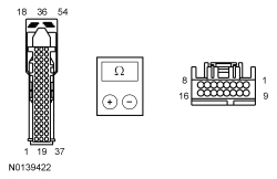 | Yes
GO to M5 . No REPAIR the circuit in question. TEST the system for normal operation. | ||||||||||||||||||||||||
| M5 CHECK FOR CORRECT APIM OPERATION | |||||||||||||||||||||||||
| Yes
CHECK OASIS for any applicable TSBs. If a TSB exists for this concern, DISCONTINUE this test and FOLLOW TSB instructions. If no TSBs address this concern, For diagnosing and testing please refer to the on-line Workshop Manual. If you do not have an on-line subscription, go to www.motorcraftservice.com. If the concern is still present, GO to M6 . No The system is operating correctly at this time. The concern may have been caused by module connections. ADDRESS the root cause of any connector or pin issues. | ||||||||||||||||||||||||
| M6 CHECK FOR CORRECT ACM OPERATION | |||||||||||||||||||||||||
| Yes
CHECK OASIS for any applicable TSBs. If a TSB exists for this concern, DISCONTINUE this test and FOLLOW TSB instructions. If no TSBs address this concern, INSTALL a new ACM . REFER to Audio Control Module (ACM) . No The system is operating correctly at this time. The concern may have been caused by module connections. ADDRESS the root cause of any connector or pin issues. | ||||||||||||||||||||||||
Pinpoint Test N: The Voice Guidance Is Inoperative Or Does Not Operate Correctly
Diagnostics in this manual assume a certain skill level and knowledge of Ford-specific diagnostic practices. Refer to Diagnostic Methods in Section 100-00 for information about these practices.
Refer to Wiring Diagrams Cell 130 , Audio System/Navigation for schematic and connector information.
The voice-assisted route guidance is broadcast through the front speakers. The voice guidance volume can be adjusted using the settings on the Audio Front Control Module (ACM).
This pinpoint test is intended to diagnose the following:
NOTICE: Use the correct probe adapter(s) when making measurements. Failure to use the correct probe adapter(s) may damage the connector.
| Test Step | Result / Action to Take |
|---|---|
| N1 CHECK THE VOICE GUIDANCE SETTING | |
| Yes
The concern was caused by an incorrect customer setting. INSTRUCT the customer in the correct use of the voice guidance feature. No GO to N2 . |
| N2 CHECK THE SPEAKER OUTPUT | |
| Yes
GO to N3 . No GO to Pinpoint Test G . |
| N3 CHECK FOR CORRECT ACM OPERATION | |
| Yes
CHECK OASIS for any applicable TSBs. If a TSB exists for this concern, DISCONTINUE this test and FOLLOW TSB instructions. If no TSBs address this concern, INSTALL a new ACM . REFER to Audio Control Module (ACM) . No The system is operating correctly at this time. The concern may have been caused by module connections. ADDRESS the root cause of any connector or pin issues. |
Pinpoint Test O: The Audio Input Jack Is Inoperative Or Does Not Operate Correctly
Diagnostics in this manual assume a certain skill level and knowledge of Ford-specific diagnostic practices. Refer to Diagnostic Methods in Section 100-00 for information about these practices.
Refer to Wiring Diagrams Cell 130 , Audio System/Navigation for schematic and connector information.
Audio signals are sent from the audio input jack to the Audio Front Control Module (ACM). There are no external power or ground circuits to the audio input jack.
Audio signals are sent from the audio input jack to the Accessory Protocol Interface Module (APIM). The signals are then sent to the ACM . There are no external power or ground circuits to the audio input jack.
This pinpoint test is intended to diagnose the following:
NOTICE: Use the correct probe adapter(s) when making measurements. Failure to use the correct probe adapter(s) may damage the connector.
NOTE: Before carrying out this pinpoint test, make sure the MP3 device is operating correctly.
| Test Step | Result / Action to Take | ||||||||||||||||||||||||||||||||||||||||||||||||||||||||||||||||||||||||||||||||
|---|---|---|---|---|---|---|---|---|---|---|---|---|---|---|---|---|---|---|---|---|---|---|---|---|---|---|---|---|---|---|---|---|---|---|---|---|---|---|---|---|---|---|---|---|---|---|---|---|---|---|---|---|---|---|---|---|---|---|---|---|---|---|---|---|---|---|---|---|---|---|---|---|---|---|---|---|---|---|---|---|---|
| O1 CHECK THE AUDIO INPUT JACK AUDIO | |||||||||||||||||||||||||||||||||||||||||||||||||||||||||||||||||||||||||||||||||
| Yes
The system is operating correctly at this time. The concern may be with the customer device. No GO to O2 . | ||||||||||||||||||||||||||||||||||||||||||||||||||||||||||||||||||||||||||||||||
| O2 DETERMINE THE VEHICLE CONTENT | |||||||||||||||||||||||||||||||||||||||||||||||||||||||||||||||||||||||||||||||||
| Yes
GO to O3 . No GO to O4 . | ||||||||||||||||||||||||||||||||||||||||||||||||||||||||||||||||||||||||||||||||
| O3 CHECK THE APIM AUDIO OUTPUT | |||||||||||||||||||||||||||||||||||||||||||||||||||||||||||||||||||||||||||||||||
| Yes
GO to O4 . No GO to Pinpoint Test K . | ||||||||||||||||||||||||||||||||||||||||||||||||||||||||||||||||||||||||||||||||
| O4 CHECK THE AUDIO INPUT JACK CIRCUITS FOR A SHORT TO VOLTAGE | |||||||||||||||||||||||||||||||||||||||||||||||||||||||||||||||||||||||||||||||||
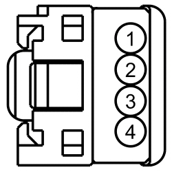 | Yes
REPAIR the circuit in question. TEST the system for normal operation. No GO to O5 . | ||||||||||||||||||||||||||||||||||||||||||||||||||||||||||||||||||||||||||||||||
| O5 CHECK THE AUDIO INPUT JACK CIRCUITS FOR AN OPEN OR SHORT TO GROUND | |||||||||||||||||||||||||||||||||||||||||||||||||||||||||||||||||||||||||||||||||
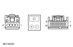
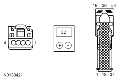 | Yes
GO to O6 . No REPAIR the circuit in question. TEST the system for normal operation. | ||||||||||||||||||||||||||||||||||||||||||||||||||||||||||||||||||||||||||||||||
| O6 ISOLATE THE AUDIO INPUT JACK | |||||||||||||||||||||||||||||||||||||||||||||||||||||||||||||||||||||||||||||||||
| Yes
The concern was caused by an inoperative audio input jack. The system is operating correctly at this time. No For vehicles without SYNC®, GO to O7 . For vehicles with SYNC®, GO to O8 . | ||||||||||||||||||||||||||||||||||||||||||||||||||||||||||||||||||||||||||||||||
| O7 CHECK FOR CORRECT ACM OPERATION | |||||||||||||||||||||||||||||||||||||||||||||||||||||||||||||||||||||||||||||||||
| Yes
CHECK OASIS for any applicable TSBs. If a TSB exists for this concern, DISCONTINUE this test and FOLLOW TSB instructions. If no TSBs address this concern, INSTALL a new ACM . REFER to Audio Control Module (ACM) . No The system is operating correctly at this time. The concern may have been caused by module connections. ADDRESS the root cause of any connector or pin issues. | ||||||||||||||||||||||||||||||||||||||||||||||||||||||||||||||||||||||||||||||||
| O8 CHECK FOR CORRECT APIM OPERATION | |||||||||||||||||||||||||||||||||||||||||||||||||||||||||||||||||||||||||||||||||
| Yes
CHECK OASIS for any applicable TSBs. If a TSB exists for this concern, DISCONTINUE this test and FOLLOW TSB instructions. If no TSBs address this concern, For diagnosing and testing please refer to the on-line Workshop Manual. If you do not have an on-line subscription, go to www.motorcraftservice.com. No The system is operating correctly at this time. The concern may have been caused by module connections. ADDRESS the root cause of any connector or pin issues. | ||||||||||||||||||||||||||||||||||||||||||||||||||||||||||||||||||||||||||||||||
Pinpoint Test P: The Universal Serial Bus (USB) Port Is Inoperative Or Does Not Operate Correctly
Diagnostics in this manual assume a certain skill level and knowledge of Ford-specific diagnostic practices. Refer to Diagnostic Methods in Section 100-00 for information about these practices.
The Universal Serial Bus (USB) port is connected to the Accessory Protocol Interface Module (APIM) through the USB cable. The USB port can be used to play audio files or upload software from mass storage devices, or for connecting a media device.
If supported by the user device, the USB can provide charging. Because of this feature, when a USB device is plugged into the USB port, the SYNC® system does not automatically switch to the device.
If a USB mass storage device is used to play an audio file, the SYNC® system only plays audio files that do not have Digital Rights Management (DRM) protection.
The USB cable and port are not serviceable separately.
This pinpoint test is intended to diagnose the following:
| Test Step | Result / Action to Take |
|---|---|
| P1 CHECK THE USB CONNECTION | |
| Yes
The SYNC® system is operating correctly. REVIEW the operation of the USB port with the customer. If the customer device still does not operate correctly, the fault is with the customer device. No GO to P2 . |
| P2 INSPECT THE USB CABLE | |
| Yes
The concern was caused by the USB connection not being seated correctly. The system is now operating correctly. No GO to P3 . |
| P3 RESET THE APIM AND RECHECK SYNC® SYSTEM OPERATION | |
NOTE: Carrying out a Master Reset returns all preference settings to the factory defaults, erases all the phone book and call histories, and deletes any devices paired with the SYNC® system. | Yes
The SYNC® system is operating correctly at this time. CARRY OUT a SYNC® system Master Reset. REFER to the Owner's Literature. REVIEW the SYNC® system operation with the customer. If the customer device still does not operate correctly, the fault is with the customer device. No If only the USB port is inoperative, GO to P4 . If additional inputs are inoperative, GO to Symptom Chart - SYNC System to diagnose the observed symptom. If all inputs are inoperative, For diagnosing and testing please refer to the on-line Workshop Manual. If you do not have an on-line subscription, go to www.motorcraftservice.com. |
| P4 ISOLATE THE USB CABLE AND PORT | |
| Yes
The concern was caused by an inoperative USB cable. The system is now operating correctly. No GO to P5 . |
| P5 CHECK FOR CORRECT APIM OPERATION | |
| Yes
CHECK OASIS for any applicable TSBs. If a TSB exists for this concern, DISCONTINUE this test and FOLLOW TSB instructions. If no TSBs address this concern, For diagnosing and testing please refer to the on-line Workshop Manual. If you do not have an on-line subscription, go to www.motorcraftservice.com. No The system is operating correctly at this time. The concern may have been caused by module connections. ADDRESS the root cause of any connector or pin issues. |
Pinpoint Test Q: Unable To Pair Bluetooth Device
Diagnostics in this manual assume a certain skill level and knowledge of Ford-specific diagnostic practices. Refer to Diagnostic Methods in Section 100-00 for information about these practices.
When a new Bluetooth device is added, the Accessory Protocol Interface Module (APIM) and the Bluetooth device must be paired together. Most Bluetooth devices can pair with the SYNC® system, although functionality may vary. To determine if a Bluetooth device is supported, retrieve the Consumer Interface Processor (CIP) software level using the Accessory Protocol Interface Module (APIM) Software Level Check , and verify the customer device is on the compatibility list for the current CIP software level.
Pairing a Bluetooth device is accomplished through the "Add Device" selection of the phone menu. When pairing a device, the SYNC® system generates a unique Personal Identification Number (PIN) that must be entered on the Bluetooth device in order for the pairing process to be successful. There are also some device-specific actions that must take place. For additional information on the pairing process, REFER to the Owner's Literature.
This pinpoint test is intended to diagnose the following:
| Test Step | Result / Action to Take |
|---|---|
| Q1 CHECK THE BLUETOOTH CONNECTION | |
NOTE: Carrying out a Master Reset returns all preference settings to the factory defaults, erases all the phone book and call histories, and deletes any devices paired with the SYNC® system. | Yes
The SYNC® system is operating correctly at this time. CARRY OUT a SYNC® system Master Reset. REFER to the Owner's Literature. REVIEW the pairing process with the customer. If the customer device still does not pair, the fault is with the customer device. No GO to Q2 . |
| Q2 CHECK FOR CORRECT APIM OPERATION | |
| Yes
CHECK OASIS for any applicable TSBs. If a TSB exists for this concern, DISCONTINUE this test and FOLLOW TSB instructions. If no TSBs address this concern, For diagnosing and testing please refer to the on-line Workshop Manual. If you do not have an on-line subscription, go to www.motorcraftservice.com. No The system is operating correctly at this time. The concern may have been caused by module connections. ADDRESS the root cause of any connector or pin issues. |
Pinpoint Test R: The Steering Wheel Switches Are Inoperative Or Do Not Operate Correctly
Diagnostics in this manual assume a certain skill level and knowledge of Ford-specific diagnostic practices. Refer to Diagnostic Methods in Section 100-00 for information about these practices.
Refer to Wiring Diagrams Cell 130 , Audio/Navigation for schematic and connector information.
There are 3 different steering wheel switch configurations:
Voltage is sent from the ACM or APIM to the steering wheel switches, and the same module grounds the return circuit. The VOL-, VOL+, SEEK-, and SEEK+ switches share signal and return circuits, while the VOICE, MEDIA, PHONE and OK switches share a separate set of signal and return circuits.
For all configurations, when a switch is pressed, the voltage is routed through a specific resistor value for each function. The ACM or APIM then uses the reference voltage to determine which control input function has been selected.
This pinpoint test is intended to diagnose the following:
NOTICE: Use the correct probe adapter(s) when making measurements. Failure to use the correct probe adapter(s) may damage the connector.
| Test Step | Result / Action to Take | |||||||||||||||||||||||||||||||||||||||||||||||
|---|---|---|---|---|---|---|---|---|---|---|---|---|---|---|---|---|---|---|---|---|---|---|---|---|---|---|---|---|---|---|---|---|---|---|---|---|---|---|---|---|---|---|---|---|---|---|---|---|
| R1 CHECK THE VEHICLE OPTION CONTENT | ||||||||||||||||||||||||||||||||||||||||||||||||
| Yes
GO to R2 . No GO to R4 . | |||||||||||||||||||||||||||||||||||||||||||||||
| R2 CHECK THE SYNC® SYSTEM OPERATION | ||||||||||||||||||||||||||||||||||||||||||||||||
NOTE: Carrying out a Master Reset returns all preference settings to the factory defaults, erases all the phone book and call histories, and deletes any devices paired with the SYNC® system. | Yes
The SYNC® system is operating correctly at this time. CARRY OUT a SYNC® system Master Reset. REFER to the Owner's Literature. REVIEW the SYNC® system operation with the customer. If the customer device still does not operate correctly, the fault is with the customer device. No GO to R3 . | |||||||||||||||||||||||||||||||||||||||||||||||
| R3 RESET THE APIM AND RECHECK SYNC® SYSTEM OPERATION | ||||||||||||||||||||||||||||||||||||||||||||||||
| Yes
The SYNC® system is operating correctly at this time. CARRY OUT a SYNC® system Master Reset. REFER to the Owner's Literature. REVIEW the SYNC® system operation with the customer. If the customer device still does not operate correctly, the fault is with the customer device. No GO to R4 . | |||||||||||||||||||||||||||||||||||||||||||||||
| R4 DETERMINE THE INOPERATIVE STEERING WHEEL SWITCHES | ||||||||||||||||||||||||||||||||||||||||||||||||
| Yes
GO to R5 . No For VOICE or PHONE steering wheel switch concerns (with SYNC® and with navigation), GO to R6 . For VOICE, PHONE, or OK steering wheel switch concerns (with SYNC® and without navigation), GO to R7 . | |||||||||||||||||||||||||||||||||||||||||||||||
| R5 MONITOR THE STEERING WHEEL SWITCH PIDs | ||||||||||||||||||||||||||||||||||||||||||||||||
| Yes
GO to R13 . No If only one PID value is incorrect or the PID value always reads one particular switch position, INSTALL new steering wheel switches. REFER to Steering Wheel Controls . CLEAR any DTCs present. TEST the system for normal operation. If multiple PID values are incorrect or read incorrectly, GO to R8 . | |||||||||||||||||||||||||||||||||||||||||||||||
| R6 MONITOR THE STEERING WHEEL SWITCH PIDs (WITH SYNC® AND NAVIGATION) | ||||||||||||||||||||||||||||||||||||||||||||||||
| Yes
GO to R13 . No If only one PID value is incorrect or the PID value always reads one particular switch position, INSTALL new steering wheel switches. REFER to Steering Wheel Controls . CLEAR any DTCs present. TEST the system for normal operation. If multiple PID values are incorrect or read incorrectly, GO to R8 . | |||||||||||||||||||||||||||||||||||||||||||||||
| R7 MONITOR THE STEERING WHEEL SWITCH PIDs (WITH SYNC® AND WITHOUT NAVIGATION) | ||||||||||||||||||||||||||||||||||||||||||||||||
| Yes
GO to R14 . No If only one PID value is incorrect or the PID value always reads one particular switch position, INSTALL new steering wheel switches. REFER to Steering Wheel Controls in this section. CLEAR any DTCs present. TEST the system for normal operation. If multiple PID values are incorrect or read incorrectly, GO to R8 . | |||||||||||||||||||||||||||||||||||||||||||||||
| R8 CHECK THE REFERENCE VOLTAGE CIRCUIT TO THE CLOCKSPRING FOR A SHORT TO VOLTAGE | ||||||||||||||||||||||||||||||||||||||||||||||||
 | Yes
REPAIR the circuit in question. CLEAR any DTCs present. TEST the system for normal operation. No GO to R9 . | |||||||||||||||||||||||||||||||||||||||||||||||
| R9 CHECK THE CIRCUITS TO THE CLOCKSPRING FOR AN OPEN OR SHORT TO GROUND | ||||||||||||||||||||||||||||||||||||||||||||||||
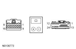
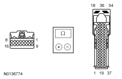 | Yes
GO to R10 . No REPAIR the circuit in question. CLEAR any DTCs present. TEST the system for normal operation. | |||||||||||||||||||||||||||||||||||||||||||||||
| R10 CHECK THE REFERENCE VOLTAGE CIRCUIT TO THE STEERING WHEEL SWITCHES FOR A SHORT TO VOLTAGE | ||||||||||||||||||||||||||||||||||||||||||||||||
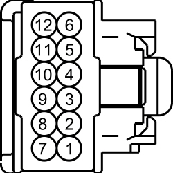 | Yes
REPAIR the circuit. CLEAR any DTCs present. TEST the system for normal operation. No GO to R11 . | |||||||||||||||||||||||||||||||||||||||||||||||
| R11 CHECK THE CIRCUITS TO THE STEERING WHEEL SWITCHES FOR AN OPEN OR SHORT TO GROUND | ||||||||||||||||||||||||||||||||||||||||||||||||
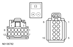 | Yes
GO to R12 . No INSTALL a new steering wheel. REFER to Section 211-04 . CLEAR any DTCs present. TEST the system for normal operation. | |||||||||||||||||||||||||||||||||||||||||||||||
| R12 CHECK THE VOLTAGE CIRCUITS TO THE CLOCKSPRING | ||||||||||||||||||||||||||||||||||||||||||||||||
| Yes
INSTALL a new clockspring. REFER to Section 501-20B . CLEAR any DTCs present. TEST the system for normal operation. No For vehicles with SYNC® and without navigation, GO to R14 . For all other vehicles, GO to R13 . | |||||||||||||||||||||||||||||||||||||||||||||||
| R13 CHECK FOR CORRECT ACM OPERATION | ||||||||||||||||||||||||||||||||||||||||||||||||
| Yes
CHECK OASIS for any applicable TSBs. If a TSB exists for this concern, DISCONTINUE this test and FOLLOW TSB instructions. If no TSBs address this concern, INSTALL a new ACM . REFER to Audio Control Module (ACM) . No The system is operating correctly at this time. The concern may have been caused by module connections. ADDRESS the root cause of any connector or pin issues. | |||||||||||||||||||||||||||||||||||||||||||||||
| R14 CHECK FOR CORRECT APIM OPERATION | ||||||||||||||||||||||||||||||||||||||||||||||||
| Yes
CHECK OASIS for any applicable TSBs. If a TSB exists for this concern, DISCONTINUE this test and FOLLOW TSB instructions. If no TSBs address this concern, For diagnosing and testing please refer to the on-line Workshop Manual. If you do not have an on-line subscription, go to www.motorcraftservice.com. No The system is operating correctly at this time. The concern may have been caused by module connections. ADDRESS the root cause of any connector or pin issues. |
Pinpoint Test S: The Audio System Does Not Operate Correctly From The Front Controls Interface Module (FCIM)
Diagnostics in this manual assume a certain skill level and knowledge of Ford-specific diagnostic practices. Refer to Diagnostic Methods in Section 100-00 for information about these practices.
When a button is pressed on the Front Controls Interface Module (FCIM), a signal is broadcast over the Medium Speed Controller Area Network (MS-CAN) to the modules in the audio system. The FCIM is also the customer interface with the HVAC module.
If the FCIM cannot communicate on the MS-CAN (due to loss of power, ground, etc.), the audio system remains in the operating state it was in prior to the failure. The steering wheel switches continue to operate.
This pinpoint test is intended to diagnose the following:
| Test Step | Result / Action to Take |
|---|---|
| S1 RETRIEVE ALL CONTINUOUS DTCs | |
| Yes
REFER to DTC Charts in this section. No GO to S2 . |
| S2 CHECK FOR DTC U2013:63 | |
| Yes
INSTALL a new FCIM . REFER to Front Controls Interface Module (FCIM) . TEST the system for normal operation. No GO to S3 . |
| S3 CHECK FOR CORRECT FCIM OPERATION | |
| Yes
CHECK OASIS for any applicable TSBs. If a TSB exists for this concern, DISCONTINUE this test and FOLLOW TSB instructions. If no TSBs address this concern, INSTALL a new FCIM . REFER to Front Controls Interface Module (FCIM) . No The system is operating correctly at this time. The concern may have been caused by module connections. ADDRESS the root cause of any connector or pin issues. |
Pinpoint Test T: The Audio System Does Not Operate Correctly From The Front Display Interface Module (FDIM) (With Navigation)
Diagnostics in this manual assume a certain skill level and knowledge of Ford-specific diagnostic practices. Refer to Diagnostic Methods in Section 100-00 for information about these practices.
Refer to Wiring Diagrams Cell 130 , Audio System/Navigation for schematic and connector information.
The Front Display Interface Module (FDIM) touchscreen sends a voltage signal to the Audio Front Control Module (ACM) when a touch sector is pressed. The ACM then takes the appropriate action, which can be a change in the audio system setting or broadcasting the information to the appropriate module through the Medium Speed Controller Area Network (MS-CAN).
This pinpoint test is intended to diagnose the following:
NOTICE: Use the correct probe adapter(s) when making measurements. Failure to use the correct probe adapter(s) may damage the connector.
| Test Step | Result / Action to Take | ||||||||||||||||||||||||
|---|---|---|---|---|---|---|---|---|---|---|---|---|---|---|---|---|---|---|---|---|---|---|---|---|---|
| T1 OBSERVE THE FDIM DISPLAY | |||||||||||||||||||||||||
| Yes
GO to Pinpoint Test W . No GO to T2 . | ||||||||||||||||||||||||
| T2 CHECK FOR AUDIO SYSTEM OPERATION FROM THE FCIM | |||||||||||||||||||||||||
| Yes
GO to T3 . No GO to Pinpoint Test S . | ||||||||||||||||||||||||
| T3 CHECK THE TOUCHSCREEN TRANSMIT AND RECEIVE CIRCUITS FOR A SHORT TO VOLTAGE | |||||||||||||||||||||||||
 | Yes
REPAIR the circuit in question. CLEAR any DTCs present. TEST the system for normal operation. No GO to T4 . | ||||||||||||||||||||||||
| T4 CHECK THE TOUCHSCREEN TRANSMIT AND RECEIVE CIRCUITS FOR AN OPEN OR SHORT TO GROUND | |||||||||||||||||||||||||
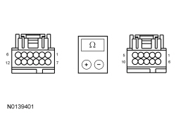 | Yes
GO to T5 . No REPAIR the circuit in question. CLEAR any DTCs present. TEST the system for normal operation. | ||||||||||||||||||||||||
| T5 ISOLATE THE FDIM | |||||||||||||||||||||||||
| Yes
The cause of the concern was an inoperative FDIM . The system is now operating correctly. No GO to T6 . | ||||||||||||||||||||||||
| T6 CHECK FOR CORRECT ACM OPERATION | |||||||||||||||||||||||||
| Yes
CHECK OASIS for any applicable TSBs. If a TSB exists for this concern, DISCONTINUE this test and FOLLOW TSB instructions. If no TSBs address this concern, INSTALL a new ACM . REFER to Audio Control Module (ACM) . No The system is operating correctly at this time. The concern may have been caused by module connections. ADDRESS the root cause of any connector or pin issues. | ||||||||||||||||||||||||
Pinpoint Test U: The Front Display Interface Module (FDIM) Is Inoperative (Without Navigation)
Diagnostics in this manual assume a certain skill level and knowledge of Ford-specific diagnostic practices. Refer to Diagnostic Methods in Section 100-00 for information about these practices.
Refer to Wiring Diagrams Cell 130 , Audio System/Navigation for schematic and connector information.
The Front Display Interface Module (FDIM) receives power at all times. The ignition switch position message is broadcast to the FDIM by the Smart Junction Box (SJB) via the Medium Speed Controller Area Network (MS-CAN).
Information from the audio system, the climate control system, the SYNC® system, and the compass heading are shown on the FDIM display screen. If only one of these displays has a concern, GO to Pinpoint Test V .
This pinpoint test is intended to diagnose the following:
| Test Step | Result / Action to Take |
|---|---|
| U1 CHECK FOR DIAGNOSTIC SCAN TOOL COMMUNICATION WITH THE FDIM | |
| Yes
GO to U2 . No REFER to Section 418-00 . |
| U2 CHECK FOR CORRECT FDIM OPERATION | |
| Yes
CHECK OASIS for any applicable TSBs. If a TSB exists for this concern, DISCONTINUE this test and FOLLOW TSB instructions. If no TSBs address this concern, INSTALL a new FDIM . REFER to Front Display Interface Module (FDIM) . No The system is operating correctly at this time. The concern may have been caused by module connections. ADDRESS the root cause of any connector or pin issues. |
Pinpoint Test V: An Individual Front Display Interface Module (FDIM) Display Is Inoperative (Without Navigation)
Diagnostics in this manual assume a certain skill level and knowledge of Ford-specific diagnostic practices. Refer to Diagnostic Methods in Section 100-00 for information about these practices.
The Front Display Interface Module (FDIM) receives inputs via the Medium Speed Controller Area Network (MS-CAN) from the following modules:
If the FDIM loses the signal from any of these modules, only that specific display is inoperative.
For the compass display, this pinpoint test is intended to diagnose a concern of the compass display being blank. For any other concerns with the compass display, including the compass being inaccurate, REFER to Section 413-01 .
This pinpoint test is intended to diagnose the following:
| Test Step | Result / Action to Take | |||||||||||||||
|---|---|---|---|---|---|---|---|---|---|---|---|---|---|---|---|---|
| V1 OBSERVE THE FDIM DISPLAY | ||||||||||||||||
| Yes
GO to Pinpoint Test U . No GO to V2 . | |||||||||||||||
| V2 CHECK FOR LOST COMMUNICATION DTCs SET IN THE FDIM | ||||||||||||||||
| Yes
REFER to DTC Charts in this section. No GO to V3 . | |||||||||||||||
| V3 CHECK THE FDIM DISPLAY SEGMENTS | ||||||||||||||||
| Yes
GO to V4 . No GO to V5 . | |||||||||||||||
| V4 OBSERVE THE SPECIFIC INOPERATIVE DISPLAY | ||||||||||||||||
| Yes
The system is operating correctly at this time. INFORM the customer on the operation of the FDIM display. No If the compass heading is inaccurate or indicates a calibration error, REFER to Section 413-01 to diagnose the compass. For all other concerns, GO to V5 . | |||||||||||||||
| V5 CHECK FOR CORRECT FDIM OPERATION | ||||||||||||||||
| Yes
CHECK OASIS for any applicable TSBs. If a TSB exists for this concern, DISCONTINUE this test and FOLLOW TSB instructions. If no TSBs address this concern, INSTALL a new FDIM . REFER to Front Display Interface Module (FDIM) . No The system is operating correctly at this time. The concern may have been caused by module connections. ADDRESS the root cause of any connector or pin issues. |
Pinpoint Test W: The Front Display Interface Module (FDIM) Is Inoperative (With Navigation)
Diagnostics in this manual assume a certain skill level and knowledge of Ford-specific diagnostic practices. Refer to Diagnostic Methods in Section 100-00 for information about these practices.
Refer to Wiring Diagrams Cell 130 , Audio System/Navigation for schematic and connector information.
The Audio Front Control Module (ACM) enables the Front Display Interface Module (FDIM) by sending voltage through the enable circuit.
Video display information is sent to the FDIM from the ACM through a dedicated video cable. The video cable is only serviced by overlaying a new cable.
If there is a fault in the video cable, the FDIM may illuminate very dimly and have a greyish appearance. This is because the enable circuit is still active and enables the illumination, but no video signal reaches the FDIM .
If the vehicle is equipped with a rear view camera, the video feed from the camera is hardwired to the FDIM .
For all other display information, including the climate control and SYNC® system displays, messages are sent to the ACM via the Medium Speed Controller Area Network (MS-CAN). The ACM then alters the video feed to the FDIM based on the messages it receives.
This pinpoint test is intended to diagnose the following:
NOTICE: Use the correct probe adapter(s) when making measurements. Failure to use the correct probe adapter(s) may damage the connector.
NOTE: Failure to disconnect the battery when instructed will result in false resistance readings. REFER to Section 414-01 .
| Test Step | Result / Action to Take | ||||||||||||||||
|---|---|---|---|---|---|---|---|---|---|---|---|---|---|---|---|---|---|
| W1 CHECK THE FDIM VOLTAGE SUPPLY | |||||||||||||||||
| Yes
GO to W2 . No VERIFY the Smart Junction Box (SJB) fuse 14 (10A) is OK. If OK, REPAIR the circuit. TEST the system for normal operation. If not OK, REFER to the Wiring Diagrams manual to identify the possible causes of the circuit short. | ||||||||||||||||
| W2 CHECK THE FDIM GROUND CIRCUIT FOR CONTINUITY | |||||||||||||||||
| Yes
GO to W3 . No REPAIR the circuit. TEST the system for normal operation. | ||||||||||||||||
| W3 CHECK THE FDIM ENABLE CIRCUIT FOR CORRECT VOLTAGE | |||||||||||||||||
| Yes
GO to W6 . No GO to W4 . | ||||||||||||||||
| W4 CHECK THE FDIM ENABLE CIRCUIT FOR A SHORT TO VOLTAGE | |||||||||||||||||
| Yes
REPAIR the circuit. TEST the system for normal operation. No GO to W5 . | ||||||||||||||||
| W5 CHECK THE FDIM ENABLE CIRCUIT FOR AN OPEN OR SHORT TO GROUND | |||||||||||||||||
| Yes
GO to W6 . No REPAIR the circuit. TEST the system for normal operation. | ||||||||||||||||
| W6 ISOLATE THE VIDEO CABLE | |||||||||||||||||
| Yes
INSTALL a new video cable for the inoperative cable. REFER to Video Cable . No GO to W7 . | ||||||||||||||||
| W7 ISOLATE THE FDIM | |||||||||||||||||
| Yes
The cause of the concern was an inoperative FDIM . The system is now operating correctly. No GO to W8 . | ||||||||||||||||
| W8 CHECK FOR CORRECT ACM OPERATION | |||||||||||||||||
| Yes
CHECK OASIS for any applicable TSBs. If a TSB exists for this concern, DISCONTINUE this test and FOLLOW TSB instructions. If no TSBs address this concern, INSTALL a new ACM . REFER to Audio Control Module (ACM) . No The system is operating correctly at this time. The concern may have been caused by module connections. ADDRESS the root cause of any connector or pin issues. | ||||||||||||||||
Pinpoint Test X: An Individual FDIM Display Is Inoperative (With Navigation)
Diagnostics in this manual assume a certain skill level and knowledge of Ford-specific diagnostic practices. Refer to Diagnostic Methods in Section 100-00 for information about these practices.
The Front Display Interface Module (FDIM) display provides information based on the video signal from the Audio Front Control Module (ACM). The ACM receives inputs via the Medium Speed Controller Area Network (MS-CAN) from the following modules:
If the ACM loses the signal from any of these modules, only that specific display is inoperative.
This pinpoint test is intended to diagnose the following:
| Test Step | Result / Action to Take | ||||||||||||
|---|---|---|---|---|---|---|---|---|---|---|---|---|---|
| X1 OBSERVE THE FDIM DISPLAY | |||||||||||||
| Yes
GO to Pinpoint Test W . No GO to X2 . | ||||||||||||
| X2 CHECK THE FDIM DISPLAY SEGMENTS | |||||||||||||
| Yes
GO to X3 . No GO to X5 . | ||||||||||||
| X3 OBSERVE THE SPECIFIC INOPERATIVE DISPLAY | |||||||||||||
| Yes
The system is operating correctly at this time. INFORM the customer on the operation of the FDIM displays. No GO to X4 . | ||||||||||||
| X4 CHECK FOR LOST COMMUNICATION DTCs | |||||||||||||
| Yes
REFER to DTC Charts in this section. No GO to X5 . | ||||||||||||
| X5 CHECK FOR CORRECT FDIM OPERATION | |||||||||||||
| Yes
CHECK OASIS for any applicable TSBs. If a TSB exists for this concern, DISCONTINUE this test and FOLLOW TSB instructions. If no TSBs address this concern, INSTALL a new FDIM . REFER to Front Display Interface Module (FDIM) . TEST the system for normal operation. If the concern is still present, GO to X6 . No The system is operating correctly at this time. The concern may have been caused by module connections. ADDRESS the root cause of any connector or pin issues. | ||||||||||||
| X6 CHECK FOR CORRECT ACM OPERATION | |||||||||||||
| Yes
CHECK OASIS for any applicable TSBs. If a TSB exists for this concern, DISCONTINUE this test and FOLLOW TSB instructions. If no TSBs address this concern, INSTALL a new ACM . REFER to Audio Control Module (ACM) . No The system is operating correctly at this time. The concern may have been caused by module connections. ADDRESS the root cause of any connector or pin issues. |
Pinpoint Test Y: The Front Display Interface Module (FDIM) Does Not Display Video From The Audio Front Control Module (ACM) (With Navigation)
Diagnostics in this manual assume a certain skill level and knowledge of Ford-specific diagnostic practices. Refer to Diagnostic Methods in Section 100-00 for information about these practices.
Refer to Wiring Diagrams Cell 130 , Audio System/Navigation for schematic and connector information.
The Audio Front Control Module (ACM) transmits video to the Front Display Interface Module (FDIM) through dedicated video circuits. This video feed is separate from all other video sources, making it possible for the FDIM to operate correctly until a DVD video is played.
DVD playback through the ACM is only enabled when the vehicle is in PARK. In all other gears, only the DVD audio is played. This is normal operation.
This pinpoint test is intended to diagnose the following:
NOTICE: Use the correct probe adapter(s) when making measurements. Failure to use the correct probe adapter(s) may damage the connector.
| Test Step | Result / Action to Take | ||||||||||||||||||||||||
|---|---|---|---|---|---|---|---|---|---|---|---|---|---|---|---|---|---|---|---|---|---|---|---|---|---|
| Y1 CHECK THE FDIM VIDEO FEED CIRCUITS FOR A SHORT TO VOLTAGE | |||||||||||||||||||||||||
| Yes
REPAIR the circuit in question. TEST the system for normal operation. No GO to Y2 . | ||||||||||||||||||||||||
| Y2 CHECK THE FDIM VIDEO FEED CIRCUITS FOR AN OPEN OR SHORT TO GROUND | |||||||||||||||||||||||||
| No REPAIR the circuit in question. TEST the system for normal operation. Yes GO to Y3 . | ||||||||||||||||||||||||
| Y3 ISOLATE THE FDIM | |||||||||||||||||||||||||
| Yes
The cause of the concern was an inoperative FDIM . The system is now operating correctly. No GO to Y4 . | ||||||||||||||||||||||||
| Y4 CHECK FOR CORRECT ACM OPERATION | |||||||||||||||||||||||||
| Yes
CHECK OASIS for any applicable TSBs. If a TSB exists for this concern, DISCONTINUE this test and FOLLOW TSB instructions. If no TSBs address this concern, INSTALL a new ACM . REFER to Audio Control Module (ACM) . No The system is operating correctly at this time. The concern may have been caused by module connections. ADDRESS the root cause of any connector or pin issues. | ||||||||||||||||||||||||
Pinpoint Test Z: Voice Recognition Is Inoperative Or Does Not Operate Correctly
Diagnostics in this manual assume a certain skill level and knowledge of Ford-specific diagnostic practices. Refer to Diagnostic Methods in Section 100-00 for information about these practices.
Refer to Wiring Diagrams Cell 130 , Audio System/Navigation for schematic and connector information.
The VOICE switch is wired to the Accessory Protocol Interface Module (APIM). When the VOICE switch is pressed, it changes a reference voltage signal, and the audio system enters voice recognition mode. A microphone contained in the overhead console receives the voice command and sends a signal to the APIM . The microphone is also used to detect outgoing audio during a phone call.
The VOICE switch is wired to the Audio Front Control Module (ACM). When the VOICE switch is pressed, it changes a reference voltage signal, and the audio system enters voice recognition mode. A microphone contained in the overhead console receives the voice command and sends a signal to the APIM . The APIM receives the microphone input and also broadcasts it to the ACM . The first voice commands spoken determine which system handles the voice commands.
The microphone test is available through the diagnostic scan tool or through the ACM self-diagnostic mode. Running this test causes the ACM to produce a test tone. If the system is operating correctly, the microphone detects the tone and produces a signal to the ACM , indicating the tone was heard.
This pinpoint test is intended to diagnose the following:
NOTICE: Use the correct probe adapter(s) when making measurements. Failure to use the correct probe adapter(s) may damage the connector.
NOTE: Failure to disconnect the battery when instructed will result in false resistance readings. REFER to Section 414-01 .
| Test Step | Result / Action to Take | ||||||||||||||||||||||||||||
|---|---|---|---|---|---|---|---|---|---|---|---|---|---|---|---|---|---|---|---|---|---|---|---|---|---|---|---|---|---|
| Z1 CHECK THE OPERATION OF THE STEERING WHEEL SWITCHES | |||||||||||||||||||||||||||||
| Yes
For vehicles with SYNC® and with navigation, GO to Z2 . For vehicles with SYNC® and without navigation, GO to Z5 . No GO to Pinpoint Test R to diagnose the steering wheel switches. | ||||||||||||||||||||||||||||
| Z2 CHECK THE MICROPHONE SIGNAL TO THE ACM | |||||||||||||||||||||||||||||
NOTE: ACM C290A must be disconnected after the ACM is powered on, or the ACM will not receive the RUN message over the network.
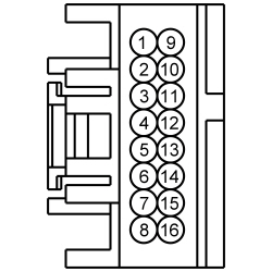 | Yes
GO to Z9 . No GO to Z3 . | ||||||||||||||||||||||||||||
| Z3 CHECK THE MICROPHONE CIRCUITS TO THE ACM FOR A SHORT TO VOLTAGE | |||||||||||||||||||||||||||||
| Yes
REPAIR the circuit in question. TEST the system for normal operation. No GO to Z4 . | ||||||||||||||||||||||||||||
| Z4 CHECK THE MICROPHONE CIRCUITS TO THE ACM FOR AN OPEN OR SHORT TO GROUND | |||||||||||||||||||||||||||||
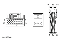 | Yes
GO to Z5 . No REPAIR the circuit in question. TEST the system for normal operation. | ||||||||||||||||||||||||||||
| Z5 CHECK THE MICROPHONE CIRCUITS TO THE APIM FOR A SHORT TO VOLTAGE | |||||||||||||||||||||||||||||
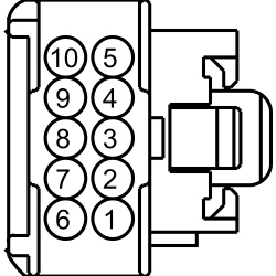
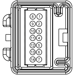 | Yes
REPAIR the circuit in question. TEST the system for normal operation. No GO to Z6 . | ||||||||||||||||||||||||||||
| Z6 CHECK THE MICROPHONE CIRCUITS TO THE APIM FOR AN OPEN OR SHORT TO GROUND | |||||||||||||||||||||||||||||
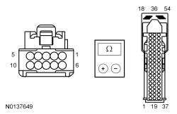
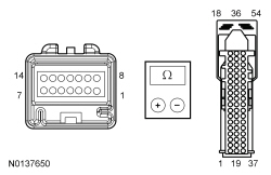 | Yes
GO to Z7 . No REPAIR the circuit in question. TEST the system for normal operation. | ||||||||||||||||||||||||||||
| Z7 CHECK THE MICROPHONE CIRCUITS FOR A SHORT TOGETHER | |||||||||||||||||||||||||||||
| Yes
GO to Z8 . No REPAIR the circuits. TEST the system for normal operation. | ||||||||||||||||||||||||||||
| Z8 CHECK FOR CORRECT APIM OPERATION | |||||||||||||||||||||||||||||
| Yes
CHECK OASIS for any applicable TSBs. If a TSB exists for this concern, DISCONTINUE this test and FOLLOW TSB instructions. If no TSBs address this concern, For diagnosing and testing please refer to the on-line Workshop Manual. If you do not have an on-line subscription, go to www.motorcraftservice.com. If the concern is still present, GO to Z9 . No The system is operating correctly at this time. The concern may have been caused by module connections. ADDRESS the root cause of any connector or pin issues. | ||||||||||||||||||||||||||||
| Z9 CHECK FOR CORRECT ACM OPERATION | |||||||||||||||||||||||||||||
| Yes
CHECK OASIS for any applicable TSBs. If a TSB exists for this concern, DISCONTINUE this test and FOLLOW TSB instructions. If no TSBs address this concern, INSTALL a new ACM . REFER to Audio Control Module (ACM) . No The system is operating correctly at this time. The concern may have been caused by module connections. ADDRESS the root cause of any connector or pin issues. | ||||||||||||||||||||||||||||
Pinpoint Test AA: No Global Positioning System (GPS) Antenna Signal
Diagnostics in this manual assume a certain skill level and knowledge of Ford-specific diagnostic practices. Refer to Diagnostic Methods in Section 100-00 for information about these practices.
The Global Positioning System (GPS) antenna provides information from the GPS satellite system to the Audio Front Control Module (ACM). This information is used to calculate position and direction of travel.
A splitter is used in the front satellite radio antenna cable to split the signals between the satellite radio and the GPS . It is possible that a concern in the GPS signal line after the splitter may cause a navigation system concern without affecting the satellite radio.
This pinpoint test is intended to diagnose the following:
| Test Step | Result / Action to Take |
|---|---|
| AA1 CHECK THE SATELLITE SIGNAL PID (SAT_SIG_STR) | |
| Yes
GO to Pinpoint Test B . No GO to AA2 . |
| AA2 CHECK FOR GPS SIGNAL-RELATED DTCs | |
| Yes
INSTALL a new front satellite radio antenna cable. REFER to Antenna Cable — Satellite Radio . CLEAR the DTCs. TEST the system for normal operation. No GO to AA3 . |
| AA3 CHECK FOR CORRECT ACM OPERATION | |
| Yes
CHECK OASIS for any applicable TSBs. If a TSB exists for this concern, DISCONTINUE this test and FOLLOW TSB instructions. If no TSBs address this concern, INSTALL a new ACM . REFER to Audio Control Module (ACM) . No The system is operating correctly at this time. The concern may have been caused by module connections. ADDRESS the root cause of any connector or pin issues. |
Pinpoint Test AB: The Position Cursor Is Inaccurate
Diagnostics in this manual assume a certain skill level and knowledge of Ford-specific diagnostic practices. Refer to Diagnostic Methods in Section 100-00 for information about these practices.
The primary source of vehicle location for the navigation system is the Audio Front Control Module (ACM) receiving the position signal through the Global Positioning System (GPS) antenna (integral to the satellite radio antenna).
In addition, the ACM receives the navigation rolling wheel count signal from the Instrument Panel Cluster (IPC), which gateways the signal from the ABS module. This secondary signal is used to calculate vehicle position when the GPS signal is lost. It also supports the adaptive learning function of the ACM , whereby the ACM can compensate for long-term differences between the GPS signal location and the actual distance traveled by the vehicle.
If DTC B119F:01 or DTC B119F:13 are present, GO to Pinpoint Test AA to diagnose a concern with the GPS antenna.
This pinpoint test is intended to diagnose the following:
| Test Step | Result / Action to Take |
|---|---|
| AB1 CHECK THE ACM FOR GPS SIGNAL-RELATED DTCs | |
| Yes
GO to Pinpoint Test AA . No GO to AB2 . |
| AB2 CHECK FOR DTC U0155:00 | |
| Yes
GO to Pinpoint Test AI . No GO to AB3 . |
| AB3 CHECK FOR CORRECT ACM OPERATION | |
| Yes
CHECK OASIS for any applicable TSBs. If a TSB exists for this concern, DISCONTINUE this test and FOLLOW TSB instructions. If no TSBs address this concern, INSTALL a new ACM . REFER to Audio Control Module (ACM) . No The system is operating correctly at this time. The concern may have been caused by module connections. ADDRESS the root cause of any connector or pin issues. |
Pinpoint Test AC: DTC B1318
Diagnostics in this manual assume a certain skill level and knowledge of Ford-specific diagnostic practices. Refer to Diagnostic Methods in Section 100-00 for information about these practices.
Refer to Wiring Diagrams Cell 130 , Audio System/Navigation for schematic and connector information.
This pinpoint test is intended to diagnose the following:
NOTICE: Use the correct probe adapter(s) when making measurements. Failure to use the correct probe adapter(s) may damage the connector.
| Test Step | Result / Action to Take | ||||||||||||
|---|---|---|---|---|---|---|---|---|---|---|---|---|---|
| AC1 RECHECK FOR DTC B1318 | |||||||||||||
| Yes
GO to AC2 . No The system is operating correctly at this time. The DTC may have been set due to a previous low battery voltage condition. | ||||||||||||
| AC2 CHECK FOR CHARGING SYSTEM DTCS IN THE PCM | |||||||||||||
| Yes
REFER to PCM DTC Chart in Section 414-00 . No GO to AC3 . | ||||||||||||
| AC3 CHECK THE BATTERY CONDITION AND STATE OF CHARGE | |||||||||||||
| Yes
GO to AC4 . No REFER to the Symptom Chart in Section 414-01 . | ||||||||||||
| AC4 CHECK THE FDIM VOLTAGE SUPPLY | |||||||||||||
| Yes
GO to AC5 . No REPAIR the circuit for high resistance. | ||||||||||||
| AC5 CHECK THE FDIM GROUND CIRCUIT FOR CONTINUITY | |||||||||||||
| Yes
GO to AC6 . No REPAIR the circuit for high resistance. | ||||||||||||
| AC6 CHECK FOR CORRECT FDIM OPERATION | |||||||||||||
| Yes
CHECK OASIS for any applicable TSBs. If a TSB exists for this concern, DISCONTINUE this test and FOLLOW TSB instructions. If no TSBs address this concern, INSTALL a new FDIM . REFER to Front Display Interface Module (FDIM) . No The system is operating correctly at this time. The concern may have been caused by module connections. ADDRESS the root cause of any connector or pin issues. | ||||||||||||
Pinpoint Test AD: DTC U0100:00
Diagnostics in this manual assume a certain skill level and knowledge of Ford-specific diagnostic practices. Refer to Diagnostic Methods in Section 100-00 for information about these practices.
The Accessory Protocol Interface Module (APIM) receives network messages from the PCM via the High Speed Controller Area Network (HS-CAN). These messages include the odometer reading and the fuel level.
As other modules outside of the audio system also receive these messages, all modules receiving a particular message should exhibit a symptom if the message is missing.
This pinpoint test is intended to diagnose the following:
| Test Step | Result / Action to Take |
|---|---|
| AD1 CHECK FOR LOST COMMUNICATION DTCs | |
| Yes
GO to AD2 . No The system is operating correctly at this time. The DTC may have been set due to an intermittent fault in the network wiring. |
| AD2 CHECK FOR BATTERY VOLTAGE OUT-OF-RANGE DTCs | |
| Yes
For the APIM and GPSM , REFER to DTC Charts in this section. For all other modules, REFER to Section 419-10 . No GO to AD3 . |
| AD3 CHECK FOR DTC U0100 OR DTC U0100:00 SET IN MULTIPLE MODULES | |
| Yes
GO to AD4 . No If there is an observable symptom, GO to Symptom Chart - General Audio System to diagnose the observed symptom. If there is no observable symptom, CHECK the wiring between the APIM and PCM and between the GPSM and PCM for a fault. |
| AD4 CHECK FOR CORRECT PCM OPERATION | |
| Yes
CHECK OASIS for any applicable TSBs. If a TSB exists for this concern, DISCONTINUE this test and FOLLOW TSB instructions. If no TSBs address this concern, INSTALL a new PCM . REFER to Section 303-14 . No The system is operating correctly at this time. The concern may have been caused by module connections. ADDRESS the root cause of any connector or pin issues. |
Pinpoint Test AE: DTC U0140
Diagnostics in this manual assume a certain skill level and knowledge of Ford-specific diagnostic practices. Refer to Diagnostic Methods in Section 100-00 for information about these practices.
Several audio system modules receive network messages from the Smart Junction Box (SJB) via the Medium Speed Controller Area Network (MS-CAN). The following information is included in the messages:
As more than one module receives these messages, all modules receiving a particular message should exhibit a symptom if the message is missing.
This pinpoint test is intended to diagnose the following:
| Test Step | Result / Action to Take |
|---|---|
| AE1 VERIFY THE CUSTOMER'S CONCERN | |
| Yes
GO to AE2 . No The system is operating correctly at this time. The DTC may have been set due to high network traffic or an intermittent fault condition. |
| AE2 RECHECK FOR DTC U0140 | |
| Yes
GO to AE3 . No The system is operating correctly at this time. The DTC may have been set due to high network traffic or an intermittent fault condition. |
| AE3 CHECK THE SJB FOR BATTERY VOLTAGE OUT-OF-RANGE DTCS | |
| Yes
REFER to SJB DTC Chart in Section 419-10 . No GO to AE4 . |
| AE4 CHECK FOR CORRECT SJB OPERATION | |
| Yes
CHECK OASIS for any applicable TSBs. If a TSB exists for this concern, DISCONTINUE this test and FOLLOW TSB instructions. If no TSBs address this concern, INSTALL a new SJB . REFER to Section 419-10 . No The system is operating correctly at this time. The concern may have been caused by module connections. ADDRESS the root cause of any connector or pin issues. |
Pinpoint Test AF: DTC U0140:00
Diagnostics in this manual assume a certain skill level and knowledge of Ford-specific diagnostic practices. Refer to Diagnostic Methods in Section 100-00 for information about these practices.
Several audio system modules receive network messages from the Smart Junction Box (SJB) via the Medium Speed Controller Area Network (MS-CAN). The following information is included in the messages:
As more than one module receives these messages, all modules receiving a particular message should exhibit a symptom if the message is missing.
This pinpoint test is intended to diagnose the following:
| Test Step | Result / Action to Take |
|---|---|
| AF1 VERIFY THE CUSTOMER'S CONCERN | |
| Yes
GO to AF2 . No The system is operating correctly at this time. The DTC may have been set due to high network traffic or an intermittent fault condition. |
| AF2 RECHECK FOR DTC U0140:00 | |
| Yes
GO to AF3 . No The system is operating correctly at this time. The DTC may have been set due to high network traffic or an intermittent fault condition. |
| AF3 CHECK THE SJB FOR BATTERY VOLTAGE OUT-OF-RANGE DTCS | |
| Yes
REFER to SJB DTC Chart in Section 419-10 . No GO to AF4 . |
| AF4 CHECK FOR BATTERY VOLTAGE OUT-OF-RANGE DTCs | |
| Yes
For DTC U3003:16, GO to Pinpoint Test AT For DTC U3003:17, GO to Pinpoint Test au No GO to AF5 . |
| AF5 CHECK FOR DTC U0140:00 SET IN MULTIPLE MODULES | |
| Yes
GO to AF6 . No If there is an observable symptom, GO to Symptom Chart - General Audio System to diagnose the observed symptom. If there is no observable symptom, the system is operating correctly at this time. The DTC may have been set due to high network traffic or an intermittent fault condition. |
| AF6 CHECK FOR CORRECT SJB OPERATION | |
| Yes
CHECK OASIS for any applicable TSBs. If a TSB exists for this concern, DISCONTINUE this test and FOLLOW TSB instructions. If no TSBs address this concern, INSTALL a new SJB . REFER to Section 419-10 . No The system is operating correctly at this time. The concern may have been caused by module connections. ADDRESS the root cause of any connector or pin issues. |
Pinpoint Test AG: DTC U0151:00
Diagnostics in this manual assume a certain skill level and knowledge of Ford-specific diagnostic practices. Refer to Diagnostic Methods in Section 100-00 for information about these practices.
The Accessory Protocol Interface Module (APIM) receives the eCall status message from the Restraints Control Module (RCM) via the High Speed Controller Area Network (HS-CAN). This message indicates the status of the emergency call system to the APIM .
This pinpoint test is intended to diagnose the following:
| Test Step | Result / Action to Take |
|---|---|
| AG1 CHECK FOR LOST COMMUNICATION DTCs | |
| Yes
GO to AG2 . No The system is operating correctly at this time. The DTC may have been set due to an intermittent fault in the network wiring. |
| AG2 CHECK FOR BATTERY VOLTAGE OUT-OF-RANGE DTCs | |
| Yes
For the APIM , REFER to DTC Charts in this section. For all other modules, REFER to Section 419-10 . No GO to AG3 . |
| AG3 CHECK FOR DTC U0151 OR DTC U0151:00 SET IN MULTIPLE MODULES | |
| Yes
GO to AG4 . No If there is an observable audio system symptom, GO to Symptom Chart - General Audio System to diagnose the observed symptom. If there is an observable restraints system symptom, REFER to Section 501-20B to diagnose the symptom. If there is no observable symptom, CHECK the wiring between the APIM and the RCM for a fault. |
| AG4 CHECK FOR CORRECT RCM OPERATION | |
| Yes
CHECK OASIS for any applicable TSBs. If a TSB exists for this concern, DISCONTINUE this test and FOLLOW TSB instructions. If no TSBs address this concern, INSTALL a new RCM . REFER to Section 501-20B . No The system is operating correctly at this time. The concern may have been caused by module connections. ADDRESS the root cause of any connector or pin issues. |
Pinpoint Test AH: DTC U0155
Diagnostics in this manual assume a certain skill level and knowledge of Ford-specific diagnostic practices. Refer to Diagnostic Methods in Section 100-00 for information about these practices.
Several audio system modules receive network messages from the Instrument Panel Cluster (IPC) via the Medium Speed Controller Area Network (MS-CAN). The following information is included in the messages:
As more than one module receives these messages, all modules receiving a particular message should exhibit a symptom if the message is missing.
This pinpoint test is intended to diagnose the following:
| Test Step | Result / Action to Take |
|---|---|
| AH1 VERIFY THE CUSTOMER'S CONCERN | |
| Yes
GO to AH2 . No The system is operating correctly at this time. The DTC may have been set due to high network traffic or an intermittent fault condition. |
| AH2 RECHECK FOR DTC U0155 | |
| Yes
GO to AH3 . No The system is operating correctly at this time. The DTC may have been set due to high network traffic or an intermittent fault condition. |
| AH3 CHECK THE IPC FOR BATTERY VOLTAGE OUT-OF-RANGE DTCS | |
| Yes
REFER to IPC DTC Chart in Section 413-01 . No GO to AH4 . |
| AH4 CHECK FOR CORRECT IPC OPERATION | |
| Yes
CHECK OASIS for any applicable TSBs. If a TSB exists for this concern, DISCONTINUE this test and FOLLOW TSB instructions. If no TSBs address this concern, INSTALL a new IPC . REFER to Section 413-01 . No The system is operating correctly at this time. The concern may have been caused by module connections. ADDRESS the root cause of any connector or pin issues. |
Pinpoint Test AI: DTC U0155:00
Diagnostics in this manual assume a certain skill level and knowledge of Ford-specific diagnostic practices. Refer to Diagnostic Methods in Section 100-00 for information about these practices.
Several audio system modules receive network messages from the Instrument Panel Cluster (IPC) via the Medium Speed Controller Area Network (MS-CAN). The following information is included in the messages:
As more than one module receives these messages, all modules receiving a particular message should exhibit a symptom if the message is missing.
This pinpoint test is intended to diagnose the following:
| Test Step | Result / Action to Take |
|---|---|
| AI1 VERIFY THE CUSTOMER'S CONCERN | |
| Yes
GO to AI2 . No The system is operating correctly at this time. The DTC may have been set due to high network traffic or an intermittent fault condition. |
| AI2 RECHECK FOR DTC U0155:00 | |
| Yes
GO to AI3 . No The system is operating correctly at this time. The DTC may have been set due to high network traffic or an intermittent fault condition. |
| AI3 CHECK THE IPC FOR BATTERY VOLTAGE OUT-OF-RANGE DTCS | |
| Yes
REFER to IPC DTC Chart in Section 413-01 . No GO to AI4 . |
| AI4 CHECK FOR BATTERY VOLTAGE OUT-OF-RANGE DTCs | |
| Yes
For DTC U3003:16, GO to Pinpoint Test AT For DTC U3003:17, GO to Pinpoint Test au No GO to AI5 . |
| AI5 CHECK FOR DTC U0155:00 SET IN MULTIPLE MODULES | |
| Yes
GO to AI6 . No If there is an observable symptom, GO to Symptom Chart - General Audio System to diagnose the observed symptom. If there is no observable symptom, the system is operating correctly at this time. The DTC may have been set due to high network traffic or an intermittent fault condition. |
| AI6 CHECK FOR CORRECT IPC OPERATION | |
| Yes
CHECK OASIS for any applicable TSBs. If a TSB exists for this concern, DISCONTINUE this test and FOLLOW TSB instructions. If no TSBs address this concern, INSTALL a new IPC . REFER to Section 413-01 . No The system is operating correctly at this time. The concern may have been caused by module connections. ADDRESS the root cause of any connector or pin issues. |
Pinpoint Test AJ: DTC U0159:00
Diagnostics in this manual assume a certain skill level and knowledge of Ford-specific diagnostic practices. Refer to Diagnostic Methods in Section 100-00 for information about these practices.
This pinpoint test is intended to diagnose the following:
| Test Step | Result / Action to Take |
|---|---|
| AJ1 VERIFY THE CUSTOMER'S CONCERN | |
| Yes
GO to AJ2 . No The system is operating correctly at this time. The DTC may have been set due to high network traffic or an intermittent fault condition. |
| AJ2 RECHECK FOR DTC U0159:00 | |
| Yes
GO to AJ3 . No The system is operating correctly at this time. The DTC may have been set due to high network traffic or an intermittent fault condition. |
| AJ3 CHECK THE PAM FOR BATTERY VOLTAGE OUT-OF-RANGE DTCS | |
| Yes
REFER to PAM DTC Chart in Section 413-13 . No GO to AJ4 . |
| AJ4 CHECK THE ACM FOR BATTERY VOLTAGE OUT-OF-RANGE DTCS | |
| Yes
For DTC U3003:16, GO to Pinpoint Test AT For DTC U3003:17, GO to Pinpoint Test au No GO to AJ5 . |
| AJ5 CHECK FOR CORRECT PAM OPERATION | |
| Yes
CHECK OASIS for any applicable TSBs. If a TSB exists for this concern, DISCONTINUE this test and FOLLOW TSB instructions. If no TSBs address this concern, INSTALL a new PAM . REFER to Section 413-13 . No The system is operating correctly at this time. The concern may have been caused by module connections. ADDRESS the root cause of any connector or pin issues. |
Pinpoint Test AK: DTC U0164
Diagnostics in this manual assume a certain skill level and knowledge of Ford-specific diagnostic practices. Refer to Diagnostic Methods in Section 100-00 for information about these practices.
Some audio system modules receive network messages from the HVAC module via the Medium Speed Controller Area Network (MS-CAN). The following information is included in the messages:
As more than one module receives these messages, all modules receiving a particular message should exhibit a symptom if the message is missing.
This pinpoint test is intended to diagnose the following:
| Test Step | Result / Action to Take |
|---|---|
| AK1 VERIFY THE CUSTOMER'S CONCERN | |
| Yes
GO to AK2 . No The system is operating correctly at this time. The DTC may have been set due to high network traffic or an intermittent fault condition. |
| AK2 RECHECK FOR DTC U0164 | |
| Yes
GO to AK3 . No The system is operating correctly at this time. The DTC may have been set due to high network traffic or an intermittent fault condition. |
| AK3 CHECK THE HVAC MODULE FOR BATTERY VOLTAGE OUT-OF-RANGE DTCS | |
| Yes
REFER to HVAC module DTC Chart in Section 412-00 . No GO to AK4 . |
| AK4 CHECK FOR DTC B1318 SET IN THE FDIM | |
| Yes
GO to Pinpoint Test AC No GO to AK5 . |
| AK5 CHECK FOR CORRECT HVAC MODULE OPERATION | |
| Yes
CHECK OASIS for any applicable TSBs. If a TSB exists for this concern, DISCONTINUE this test and FOLLOW TSB instructions. If no TSBs address this concern, INSTALL a new HVAC module. REFER to Section 412-01 . No The system is operating correctly at this time. The concern may have been caused by module connections. ADDRESS the root cause of any connector or pin issues. |
Pinpoint Test AL: DTC U0164:00
Diagnostics in this manual assume a certain skill level and knowledge of Ford-specific diagnostic practices. Refer to Diagnostic Methods in Section 100-00 for information about these practices.
Some audio system modules receive network messages from the HVAC module via the Medium Speed Controller Area Network (MS-CAN). The following information is included in the messages:
As more than one module receives these messages, all modules receiving a particular message should exhibit a symptom if the message is missing.
This pinpoint test is intended to diagnose the following:
| Test Step | Result / Action to Take |
|---|---|
| AL1 VERIFY THE CUSTOMER'S CONCERN | |
| Yes
GO to AL2 . No The system is operating correctly at this time. The DTC may have been set due to high network traffic or an intermittent fault condition. |
| AL2 RECHECK FOR DTC U0164 | |
| Yes
GO to AL3 . No The system is operating correctly at this time. The DTC may have been set due to high network traffic or an intermittent fault condition. |
| AL3 CHECK THE HVAC MODULE FOR BATTERY VOLTAGE OUT-OF-RANGE DTCS | |
| Yes
REFER to HVAC module DTC Chart in Section 412-00 . No GO to AL4 . |
| AL4 CHECK THE ACM FOR BATTERY VOLTAGE OUT-OF-RANGE DTCS | |
| Yes
For DTC U3003:16, GO to Pinpoint Test AT For DTC U3003:17, GO to Pinpoint Test au No GO to AL5 . |
| AL5 CHECK FOR CORRECT HVAC MODULE OPERATION | |
| Yes
CHECK OASIS for any applicable TSBs. If a TSB exists for this concern, DISCONTINUE this test and FOLLOW TSB instructions. If no TSBs address this concern, INSTALL a new HVAC module. REFER to Section 412-01 . No The system is operating correctly at this time. The concern may have been caused by module connections. ADDRESS the root cause of any connector or pin issues. |
Pinpoint Test AM: DTC U016A:00
Diagnostics in this manual assume a certain skill level and knowledge of Ford-specific diagnostic practices. Refer to Diagnostic Methods in Section 100-00 for information about these practices.
This pinpoint test is intended to diagnose the following:
| Test Step | Result / Action to Take |
|---|---|
| AM1 CHECK THE APIM DTCs | |
NOTE: If new modules were installed prior to the DTC being set, the module configuration may be incorrectly set during Programmable Module Installation (PMI) or the PMI may not have been carried out. | Yes
GO to AM2 . No The system is operating correctly at this time. The DTC may have been set due to an intermittent fault in the network wiring. |
| AM2 VERIFY THE CUSTOMER CONCERN | |
| Yes
GO to AM3 . No The system is operating correctly at this time. The DTC may have been set due to an intermittent fault in the network wiring. CHECK the MS-CAN wiring between the APIM and the GPSM for a fault. |
| AM3 CHECK THE COMMUNICATION NETWORK | |
| Yes
GO to AM4 . No REFER to Section 418-00 . |
| AM4 CHECK FOR BATTERY VOLTAGE OUT-OF-RANGE DTCs | |
| Yes
REFER to DTC Charts in this section. No GO to AM5 . |
| AM5 CHECK FOR CORRECT GPSM OPERATION | |
| Yes
CHECK OASIS for any applicable TSBs. If a TSB exists for this concern, DISCONTINUE this test and FOLLOW TSB instructions. If no TSBs address this concern, INSTALL a new GPSM . REFER to Global Positioning System Module (GPSM) . No The system is operating correctly at this time. The concern may have been caused by module connections. ADDRESS the root cause of any connector or pin issues. |
Pinpoint Test AN: DTC U0184
Diagnostics in this manual assume a certain skill level and knowledge of Ford-specific diagnostic practices. Refer to Diagnostic Methods in Section 100-00 for information about these practices.
Several audio system modules receive network messages from the Audio Front Control Module (ACM) via the Medium Speed Controller Area Network (MS-CAN). These messages consist of various audio system related information.
As more than one module receives these messages, all modules receiving a particular message should exhibit a symptom if the message is missing.
This pinpoint test is intended to diagnose the following:
| Test Step | Result / Action to Take |
|---|---|
| AN1 VERIFY THE CUSTOMER'S CONCERN | |
| Yes
GO to AN2 . No The system is operating correctly at this time. The DTC may have been set due to high network traffic or an intermittent fault condition. |
| AN2 RECHECK FOR DTC U0184 | |
| Yes
GO to AN3 . No The system is operating correctly at this time. The DTC may have been set due to high network traffic or an intermittent fault condition. |
| AN3 CHECK THE ACM FOR BATTERY VOLTAGE OUT-OF-RANGE DTCS | |
| Yes
For DTC U3003:16, GO to Pinpoint Test AT For DTC U3003:17, GO to Pinpoint Test au No GO to AN4 . |
| AN4 CHECK FOR DTC B1318 SET IN THE FDIM | |
| Yes
GO to Pinpoint Test AC No GO to AN5 . |
| AN5 CHECK FOR CORRECT ACM OPERATION | |
| Yes
CHECK OASIS for any applicable TSBs. If a TSB exists for this concern, DISCONTINUE this test and FOLLOW TSB instructions. If no TSBs address this concern, INSTALL a new ACM . REFER to Audio Control Module (ACM) . No The system is operating correctly at this time. The concern may have been caused by module connections. ADDRESS the root cause of any connector or pin issues. |
Pinpoint Test AO: DTC U0184:00
Diagnostics in this manual assume a certain skill level and knowledge of Ford-specific diagnostic practices. Refer to Diagnostic Methods in Section 100-00 for information about these practices.
Several audio system modules receive network messages from the Audio Front Control Module (ACM) via the Medium Speed Controller Area Network (MS-CAN). These messages consist of various audio system related information.
As more than one module receives these messages, all modules receiving a particular message should exhibit a symptom if the message is missing.
This pinpoint test is intended to diagnose the following:
| Test Step | Result / Action to Take |
|---|---|
| AO1 VERIFY THE CUSTOMER'S CONCERN | |
| Yes
GO to AO2 . No The system is operating correctly at this time. The DTC may have been set due to high network traffic or an intermittent fault condition. |
| AO2 RECHECK FOR DTC U0184:00 | |
| Yes
GO to AO3 . No The system is operating correctly at this time. The DTC may have been set due to high network traffic or an intermittent fault condition. |
| AO3 CHECK FOR BATTERY VOLTAGE OUT-OF-RANGE DTCs | |
| Yes
For DTC U3003:16, GO to Pinpoint Test AT For DTC U3003:17, GO to Pinpoint Test au No GO to AO4 . |
| AO4 CHECK FOR CORRECT ACM OPERATION | |
| Yes
CHECK OASIS for any applicable TSBs. If a TSB exists for this concern, DISCONTINUE this test and FOLLOW TSB instructions. If no TSBs address this concern, INSTALL a new ACM . REFER to Audio Control Module (ACM) . No The system is operating correctly at this time. The concern may have been caused by module connections. ADDRESS the root cause of any connector or pin issues. |
Pinpoint Test AP: DTC U0197
Diagnostics in this manual assume a certain skill level and knowledge of Ford-specific diagnostic practices. Refer to Diagnostic Methods in Section 100-00 for information about these practices.
Several audio system modules receive network messages from the Accessory Protocol Interface Module (APIM) via the Medium Speed Controller Area Network (MS-CAN). These messages consist of various audio system related information.
As more than one module receives these messages, all modules receiving a particular message should exhibit a symptom if the message is missing.
This pinpoint test is intended to diagnose the following:
| Test Step | Result / Action to Take |
|---|---|
| AP1 VERIFY THE CUSTOMER'S CONCERN | |
| Yes
GO to AP2 . No The system is operating correctly at this time. The DTC may have been set due to high network traffic or an intermittent fault condition. |
| AP2 RECHECK FOR DTC U0197 | |
| Yes
GO to AP3 . No The system is operating correctly at this time. The DTC may have been set due to high network traffic or an intermittent fault condition. |
| AP3 CHECK THE APIM FOR BATTERY VOLTAGE OUT-OF-RANGE DTCS | |
| Yes
For DTC U3003:16, GO to Pinpoint Test AT For DTC U3003:17, GO to Pinpoint Test au No GO to AP4 . |
| AP4 CHECK FOR DTC B1318 SET IN THE FDIM | |
| Yes
GO to Pinpoint Test AC No GO to AP5 . |
| AP5 CHECK FOR CORRECT APIM OPERATION | |
| Yes
CHECK OASIS for any applicable TSBs. If a TSB exists for this concern, DISCONTINUE this test and FOLLOW TSB instructions. If no TSBs address this concern, For diagnosing and testing please refer to the on-line Workshop Manual. If you do not have an on-line subscription, go to www.motorcraftservice.com. No The system is operating correctly at this time. The concern may have been caused by module connections. ADDRESS the root cause of any connector or pin issues. |
Pinpoint Test AQ: DTC U0197:00
Diagnostics in this manual assume a certain skill level and knowledge of Ford-specific diagnostic practices. Refer to Diagnostic Methods in Section 100-00 for information about these practices.
Several audio system modules receive network messages from the Accessory Protocol Interface Module (APIM) via the Medium Speed Controller Area Network (MS-CAN). These messages consist of various audio system related information.
As more than one module receives these messages, all modules receiving a particular message should exhibit a symptom if the message is missing.
This pinpoint test is intended to diagnose the following:
| Test Step | Result / Action to Take |
|---|---|
| AQ1 VERIFY THE CUSTOMER'S CONCERN | |
| Yes
GO to AQ2 . No The system is operating correctly at this time. The DTC may have been set due to high network traffic or an intermittent fault condition. |
| AQ2 RECHECK FOR DTC U0197:00 | |
| Yes
GO to AQ3 . No The system is operating correctly at this time. The DTC may have been set due to high network traffic or an intermittent fault condition. |
| AQ3 CHECK FOR BATTERY VOLTAGE OUT-OF-RANGE DTCs | |
| Yes
For DTC U3003:16, GO to Pinpoint Test AT For DTC U3003:17, GO to Pinpoint Test au No GO to AQ4 . |
| AQ4 CHECK FOR CORRECT APIM OPERATION | |
| Yes
CHECK OASIS for any applicable TSBs. If a TSB exists for this concern, DISCONTINUE this test and FOLLOW TSB instructions. If no TSBs address this concern, For diagnosing and testing please refer to the on-line Workshop Manual. If you do not have an on-line subscription, go to www.motorcraftservice.com. No The system is operating correctly at this time. The concern may have been caused by module connections. ADDRESS the root cause of any connector or pin issues. |
Pinpoint Test AR: DTC U0255:00
Diagnostics in this manual assume a certain skill level and knowledge of Ford-specific diagnostic practices. Refer to Diagnostic Methods in Section 100-00 for information about these practices.
This pinpoint test is intended to diagnose the following:
NOTE: Disregard the pinpoint test steps for the APIM if the concern is on a vehicle without the SYNC® system.
| Test Step | Result / Action to Take |
|---|---|
| AR1 CHECK THE ACM AND APIM DTCs | |
NOTE: If new modules were installed prior to the DTC being set, the module configuration may be incorrectly set during Programmable Module Installation (PMI) or the PMI may not have been carried out. | Yes
GO to AR2 . No The system is operating correctly at this time. The DTC may have been set due to an intermittent fault in the network wiring. |
| AR2 VERIFY THE CUSTOMER CONCERN | |
| Yes
GO to AR3 . No The system is operating correctly at this time. The DTC may have been set due to an intermittent fault in the network wiring. CHECK the MS-CAN wiring between the FDIM and the module in question for a fault. |
| AR3 CHECK THE COMMUNICATION NETWORK | |
| Yes
GO to AR4 . No REFER to Section 418-00 . |
| AR4 CHECK FOR BATTERY VOLTAGE OUT-OF-RANGE DTCs | |
| Yes
REFER to DTC Charts in this section. No INSTALL a new FDIM . REFER to Front Display Interface Module (FDIM) . CLEAR the ACM and APIM DTCs. REPEAT the ACM and APIM self-tests. If DTC U0255:00 is still present in the ACM , INSTALL a new ACM . REFER to Audio Control Module (ACM) . TEST the system for normal operation. If DTC U0255:00 is still present in the APIM , For diagnosing and testing please refer to the on-line Workshop Manual. If you do not have an on-line subscription, go to www.motorcraftservice.com. |
Pinpoint Test AS: DTC U0256:00
Diagnostics in this manual assume a certain skill level and knowledge of Ford-specific diagnostic practices. Refer to Diagnostic Methods in Section 100-00 for information about these practices.
This pinpoint test is intended to diagnose the following:
NOTE: Disregard the pinpoint test steps for the APIM if the concern is on a vehicle without the SYNC® system.
| Test Step | Result / Action to Take |
|---|---|
| AS1 CHECK THE ACM AND FDIM DTCs | |
NOTE: If new modules were installed prior to the DTC being set, the module configuration may be incorrectly set during Programmable Module Installation (PMI) or the PMI may not have been carried out. | Yes
GO to AS2 . No The system is operating correctly at this time. The DTC may have been set due to an intermittent fault in the network wiring. |
| AS2 VERIFY THE CUSTOMER CONCERN | |
| Yes
GO to AS3 . No The system is operating correctly at this time. The DTC may have been set due to an intermittent fault in the network wiring. CHECK the MS-CAN wiring between the FCIM and the module in question for a fault. |
| AS3 CHECK THE COMMUNICATION NETWORK | |
| Yes
GO to AS4 . No REFER to Section 418-00 . |
| AS4 CHECK FOR BATTERY VOLTAGE OUT-OF-RANGE DTCs | |
| Yes
REFER to DTC Charts in this section. No INSTALL a new FCIM . REFER to Front Controls Interface Module (FCIM) . CLEAR the ACM and APIM DTCs. REPEAT the ACM and APIM self-tests. If U0256:00 is still present in the ACM , INSTALL a new ACM . REFER to Audio Control Module (ACM) . TEST the system for normal operation. If DTC U0256:00 is still present in the APIM , For diagnosing and testing please refer to the on-line Workshop Manual. If you do not have an on-line subscription, go to www.motorcraftservice.com. |
Pinpoint Test AT: DTC U3003:16
Diagnostics in this manual assume a certain skill level and knowledge of Ford-specific diagnostic practices. Refer to Diagnostic Methods in Section 100-00 for information about these practices.
Refer to Wiring Diagrams Cell 130 , Audio System/Navigation for schematic and connector information.
This pinpoint test is intended to diagnose the following:
NOTICE: Use the correct probe adapter(s) when making measurements. Failure to use the correct probe adapter(s) may damage the connector.
| Test Step | Result / Action to Take | ||||||||||||||||||||||||||||||||||||||||||||||||||
|---|---|---|---|---|---|---|---|---|---|---|---|---|---|---|---|---|---|---|---|---|---|---|---|---|---|---|---|---|---|---|---|---|---|---|---|---|---|---|---|---|---|---|---|---|---|---|---|---|---|---|---|
| AT1 RECHECK FOR DTC U3003:16 | |||||||||||||||||||||||||||||||||||||||||||||||||||
| Yes
GO to AT2 . No The system is operating correctly at this time. The DTC may have been set due to a previous low battery voltage condition. | ||||||||||||||||||||||||||||||||||||||||||||||||||
| AT2 CHECK FOR CHARGING SYSTEM DTCS IN THE PCM | |||||||||||||||||||||||||||||||||||||||||||||||||||
| Yes
REFER to PCM DTC Chart in Section 414-00 . No GO to AT3 . | ||||||||||||||||||||||||||||||||||||||||||||||||||
| AT3 CHECK THE BATTERY CONDITION AND STATE OF CHARGE | |||||||||||||||||||||||||||||||||||||||||||||||||||
| Yes
GO to AT4 . No REFER to the Symptom Chart in Section 414-00 . | ||||||||||||||||||||||||||||||||||||||||||||||||||
| AT4 CHECK THE MODULE VOLTAGE SUPPLY | |||||||||||||||||||||||||||||||||||||||||||||||||||
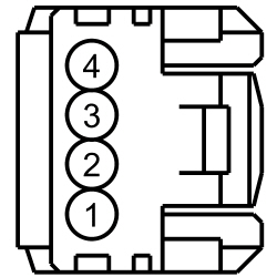
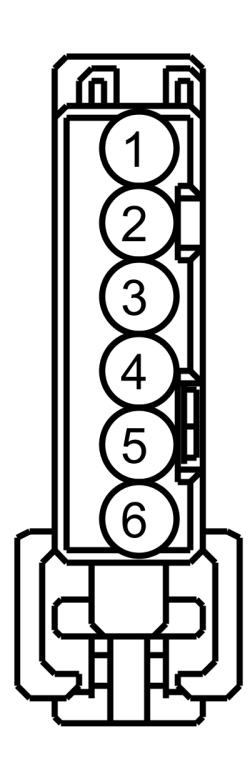 | Yes
GO to AT5 . No REPAIR the circuit for high resistance. | ||||||||||||||||||||||||||||||||||||||||||||||||||
| AT5 CHECK THE SUSPECT MODULE GROUND CIRCUIT FOR CONTINUITY | |||||||||||||||||||||||||||||||||||||||||||||||||||
| Yes
For the ACM , GO to AT6 . For the APIM , GO to AT7 . For the FCIM , GO to AT8 . For the GPSM , GO to AT9 . No REPAIR the circuit for high resistance. | ||||||||||||||||||||||||||||||||||||||||||||||||||
| AT6 CHECK FOR CORRECT ACM OPERATION | |||||||||||||||||||||||||||||||||||||||||||||||||||
| Yes
CHECK OASIS for any applicable TSBs. If a TSB exists for this concern, DISCONTINUE this test and FOLLOW TSB instructions. If no TSBs address this concern, INSTALL a new ACM . REFER to Audio Control Module (ACM) . No The system is operating correctly at this time. The concern may have been caused by module connections. ADDRESS the root cause of any connector or pin issues. | ||||||||||||||||||||||||||||||||||||||||||||||||||
| AT7 CHECK FOR CORRECT APIM OPERATION | |||||||||||||||||||||||||||||||||||||||||||||||||||
| Yes
CHECK OASIS for any applicable TSBs. If a TSB exists for this concern, DISCONTINUE this test and FOLLOW TSB instructions. If no TSBs address this concern, For diagnosing and testing please refer to the on-line Workshop Manual. If you do not have an on-line subscription, go to www.motorcraftservice.com. No The system is operating correctly at this time. The concern may have been caused by module connections. ADDRESS the root cause of any connector or pin issues. | ||||||||||||||||||||||||||||||||||||||||||||||||||
| AT8 CHECK FOR CORRECT FCIM OPERATION | |||||||||||||||||||||||||||||||||||||||||||||||||||
| Yes
CHECK OASIS for any applicable TSBs. If a TSB exists for this concern, DISCONTINUE this test and FOLLOW TSB instructions. If no TSBs address this concern, INSTALL a new FCIM . REFER to Front Controls Interface Module (FCIM) . No The system is operating correctly at this time. The concern may have been caused by module connections. ADDRESS the root cause of any connector or pin issues. | ||||||||||||||||||||||||||||||||||||||||||||||||||
| AT9 CHECK FOR CORRECT GPSM OPERATION | |||||||||||||||||||||||||||||||||||||||||||||||||||
| Yes
CHECK OASIS for any applicable TSBs. If a TSB exists for this concern, DISCONTINUE this test and FOLLOW TSB instructions. If no TSBs address this concern, INSTALL a new GPSM . REFER to Global Positioning System Module (GPSM) . No The system is operating correctly at this time. The concern may have been caused by module connections. ADDRESS the root cause of any connector or pin issues. | ||||||||||||||||||||||||||||||||||||||||||||||||||
Pinpoint Test AU: DTC U3003:17
Diagnostics in this manual assume a certain skill level and knowledge of Ford-specific diagnostic practices. Refer to Diagnostic Methods in Section 100-00 for information about these practices.
This pinpoint test is intended to diagnose the following:
| Test Step | Result / Action to Take |
|---|---|
| AU1 RECHECK FOR DTC U3003:17 | |
| Yes
GO to AU2 . No The system is operating correctly at this time. The DTC may have been set previously during battery charging or while jump starting the vehicle. |
| AU2 CHECK FOR HIGH VOLTAGE DTCs SET IN OTHER MODULES | |
| Yes
REFER to Section 414-00 to diagnose an overcharging condition. No GO to AU3 . |
| AU3 CHECK THE BATTERY VOLTAGE | |
| Yes
REFER to Section 414-00 to diagnose an overvoltage condition. No For the ACM , GO to AU4 . For the APIM , GO to AU5 . For the FCIM , GO to AU6 . For the GPSM , GO to AU7 . |
| AU4 CHECK FOR CORRECT ACM OPERATION | |
| Yes
CHECK OASIS for any applicable TSBs. If a TSB exists for this concern, DISCONTINUE this test and FOLLOW TSB instructions. If no TSBs address this concern, INSTALL a new ACM . REFER to Audio Control Module (ACM) . No The system is operating correctly at this time. The concern may have been caused by module connections. ADDRESS the root cause of any connector or pin issues. |
| AU5 CHECK FOR CORRECT APIM OPERATION | |
| Yes
CHECK OASIS for any applicable TSBs. If a TSB exists for this concern, DISCONTINUE this test and FOLLOW TSB instructions. If no TSBs address this concern, For diagnosing and testing please refer to the on-line Workshop Manual. If you do not have an on-line subscription, go to www.motorcraftservice.com. No The system is operating correctly at this time. The concern may have been caused by module connections. ADDRESS the root cause of any connector or pin issues. |
| AU6 CHECK FOR CORRECT FCIM OPERATION | |
| Yes
CHECK OASIS for any applicable TSBs. If a TSB exists for this concern, DISCONTINUE this test and FOLLOW TSB instructions. If no TSBs address this concern, INSTALL a new FCIM . REFER to Front Controls Interface Module (FCIM) . No The system is operating correctly at this time. The concern may have been caused by module connections. ADDRESS the root cause of any connector or pin issues. |
| AU7 CHECK FOR CORRECT GPSM OPERATION | |
| Yes
CHECK OASIS for any applicable TSBs. If a TSB exists for this concern, DISCONTINUE this test and FOLLOW TSB instructions. If no TSBs address this concern, INSTALL a new GPSM . REFER to Global Positioning System Module (GPSM) . No The system is operating correctly at this time. The concern may have been caused by module connections. ADDRESS the root cause of any connector or pin issues. |